Example number 1.Determine the strength of the currents flowing in the branches, if e 1 = 1 V, e 2 = 2 V, e 3 = 3 V, r 1 = 1 Ohm, r 2 = 0.5 Ohm, r 3 = Ohm, R 4 = 1 Ohm, R 5 = Ohm.
| Given: | Decision: |
| r 1 = 1 Ohm r 2 = 0.5 Ohm r 3 = ohm R 4 = 1 Ohm R 5 = Ohm |
|
| I 1 -? I 2 -? I 3 -? |
A physical system is an electrical circuit in which there are several different sources of current. It is impossible to find the resulting emf and, therefore, it is impossible to apply Ohm's law for a closed circuit. In this case, the electrical circuit can be calculated using Kirchhoff rules.
- First you need to choose (arbitrarily) the direction of the current in the branches (see fig.). If the direction is chosen incorrectly, then in the final decision the value of this current will be negative, and if it is true, then positive.
- Apply the first Kirchhoff rule. It is true for electrical circuit nodes. In this scheme there are two nodes: m. A and m. S.
For node A:
For node C, the first Kirchhoff rule gives nothing new. Apply the second Kirchhoff rule, it is valid only for closed circuits. In this scheme there are three: ABCA, ACDA, ABCDA.
Consider the contour ABCA: e 1 and e 2; r 1, r 2, R 4; I 1 and I 2.
To apply the second Kirchhoff rule, it is necessary to choose (arbitrarily) the conditionally positive direction of the circuit traversal. It is necessary to determine the signs of EMF and currents. If the direction of the EMF or current coincides with the direction of the circuit bypass, then they are considered positive. Otherwise, the EMF or current is considered negative. Therefore: (if you choose the direction of the counterclockwise bypass)
The system of equations (1 - 3) are closed, solving this system we find:
The currents I 1 and I 2 turned out negative, which means that their directions were accidentally chosen erroneously. The current I 3 is positive, therefore, its direction is chosen correctly.
Answer:; ; .
Example number 2.In the scheme presented in the figure, e 1 = 2.1 V, e 2 = 1.9 V, R 1 = 45 Ω, R 2 = 10 Ω, R 3 = 10 Ω. Find the current in all parts of the circuit. The internal resistance of the elements is neglected.

| Given: | Decision: |
| R 1 = 45 Ohm R 2 = 10 ohms R 3 = 10 ohms | We apply the Kirchhoff rules for this branched chain. Mark the directions of the currents with arrows on the diagram. For node C:. For Node A we get the identical equation. For the ABC circuit, according to the second Kirchhoff rule: For ACD circuit: |
| I 1 -? I 2 -? I 3 -? |
(Instead of an ACD or ABC contour, we could take the ABCD contour)
We have three equations with three unknowns, i.e. the system is solvable:
 Þ solving this system, we get: I 1 = 0.04 A; I 2 = -0.01 A; I 3 = 0.03 A.
A negative sign on the current I 2 indicates that the direction was chosen incorrectly. The direction of the current I 2 will actually go from D to C, and not vice versa, as was customary before the equations were compiled.
Answer:I 1 = 0.04 A; I 2 = -0.01 A; I 3 = 0.03 A.
Example number 3.Three current sources with emf e 1 = 11 V, e 2 = 4 V and e 3 = 6 V and three rheostats with resistances R 1 = 5 Ω, R 2 = 10 Ω, R 3 = 20 Ω are connected as shown in the diagram. Determine the strength of the currents I in rheostats. The internal resistance of the source is negligible.
![]() .
.
Equate: ![]() ;
;
"-" - current direction
![]() ;
;
![]() .
.
Answer:; ; .
Example number 4.Current sources by electromotive forces e 1 and e 2 are included in the circuit, as shown in the diagram. Determine the strength of the currents flowing in the resistances R 2 and R 3, if e 1 = 10 V, e 2 = 4 V, and R 1 = R 4 = 2 Ω and R 2 = R 3 = 4 Ω. Resistance sources neglected.
The missing three equations will be obtained according to the second Kirchhoff rule. To find the required number of independent equations, one should follow the rule: choose contours so that each new branch would include one branch that did not participate in any of the previously used contours.
Respectively for contours: AR 1 BR 2 A; AR 1 BR 3 A; AR 3 BR 4 A we have:
|
| ||
|
|
Substituting the numerical values of R and e into formulas (2), (3), (4), we get:

Since you need to find only 2 currents, it is convenient to use the method of determinants. To this end, we rewrite the equations again as follows:

The desired values of the currents will be found from the expressions: and, where D is the determinant of the system of equations.
DI 2 and DI 3 are determinants obtained by replacing the corresponding columns of the determinant with D columns composed of the free members of the four equations above:
 ;
;
 ;
;
 .
.
From here:
I 2 = 0; I 3 = -1A.
The sign "-" for the value of I 3, indicates that with an arbitrary choice of directions of currents, the direction of the current I 3 was indicated opposite to the true one.
Answer:I 2 = 0; I 3 = –1A; current I 3 flows from node B to node A.
Example number 5.In the figure, e 1 = 10 V, e 2 = 20 V, e 3 = 40 V, and resistances R 1 = R 2 = R 3 = R = 10 Ω. Determine the strength of the currents flowing through the resistance (I) and through the source of the EMF (I "). Ignore the internal resistance of the sources of EMF.
I 3 × 10 = 20, I 2 × 10 = 30, I 1 × 10 + 3 × 10 = 40;
I 3 = 2 A, I 2 = 3 A, I 1 = 1 A;
I 3 ’= 3 A, I 2’ = 0, I 1 ’= -2 A,
Answer: I 1 = 1 A, I 2 = 3 A, I 3 = 2 A, I 1 ’= –2 A, I 2’ = 0, I 3 ’= 3 A.
Example number 6.Two sources of current EMF e 1 = 2 V and e 2 = 1.5 V and internal resistances r 1 = 0.5 Ohms and r 2 = 0.4 Ohms are connected parallel to the resistance R = 2 Ohms. Determine the current through this resistance.
| Given: | Decision: |
| r 1 = 0.5 Ohm r 2 = 0.4 ohm R = 2 Ohm |
|
| I -? |
Answer:I = 0.775 A.
Example number 7.In the figure, e = 2 V, R 1 = 60 Ω, R 2 = 40 Ω, R 3 = R 4 = 20 Ω and R G = 100 Ω. Determine the strength of the current I G through a galvanometer.
| Given: | Decision: |
| R 1 = 60 Ohm R 2 = 40 Ohm R 3 = R 4 = 20 Ohm R G = 100 Ohm | |
| I g -? |

 ®
®

0.2 ®, ![]() ®
,
®
,
A physical system is an electrical circuit in which there are several different sources of current. It is impossible to find the resulting emf, and therefore it is impossible to apply Ohm’s law to a closed circuit. In this case, the electrical circuit can be calculated using Kirchhoff rules.
Decision:
First you need to choose (arbitrarily) the direction of the current in the branches. Select them as shown in the figure. If we make a mistake in choosing the direction of some current, then in the final decision the value of this current will be negative, if the correct direction of the current is randomly chosen, then its value will be positive.
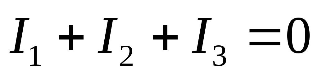
Apply the first Kirchhoff rule. It is true for electrical circuit nodes. In this scheme there are two nodes: points A and C. For node A, according to the first Kirchhoff rule, we get:
I 1 + I 2 + I 3 = 0.
For node C, the first Kirchhoff rule gives nothing new. We apply the second Kirchhoff rule. It is valid only for closed circuits. In this scheme there are three: ABCA, ASDA, ABCDA. Consider the ABCA circuit. In this circuit there are two emfs (E 1 and E 2), three resistors (r 1, r 2, R 4) and two currents (I 1 and I 2). To apply the second Kirchhoff rule, it is necessary to choose (arbitrarily) the conditionally positive direction of the circuit traversal. It is necessary to determine the signs of EMF and currents. If the directions of the EMF or current coincide with the direction of the circuit bypass, then they are considered positive. Otherwise, the EMF or current is considered negative.
We choose the direction of the counterclockwise direction for the positive direction of walking around the ABCA contour; EMF E 1 is counterclockwise, therefore, it is considered positive; EMF E 2 is directed clockwise (ie, against the direction of the circuit bypass); consequently, it will enter the equation of the second Kirchhoff rule with a minus sign. The current I 1 passes through the resistors r 1 and R 4, and its direction coincides with the direction of the circuit bypass. The current I 2 passes through the resistor r 2 and is directed against the direction of the bypass. Therefore, the current I 1 is positive, the current I 2 is negative. According to the second Kirchhoff rule for the ABCA circuit, we obtain:
If we choose a clockwise direction for the positive direction of bypassing this contour, then according to the second Kirchhoff rule we find:
Equation (1) multiplied by (–1) is obtained. Obviously, these equations are equivalent. Thus, the essence of the second Kirchhoff rule does not depend on the arbitrary choice of the direction of the loop traversal.
Consider the circuit ASDA. Let us choose counterclockwise direction for the positive direction of bypassing this contour. Applying the second Kirchhoff rule, we get:
The system of equations (1 - 2) is closed. The task is physically solved. Solving the resulting system of equations, we find:
I 1 = – A, I 2= – A, I 3 = A.
Currents I 1 and I 2 turned out negative. This means that their directions were randomly chosen erroneously. The current I 3 is positive; therefore, its direction is randomly chosen correctly.
Answer: I 1 = - A, I 2 = - A, I 3 = A.
Guidelines for course topics
DC circuits
Starting to study this section, it is necessary to have an idea about the types of generating devices, their external characteristics and modes of operation, as well as about the main types of receiving devices and their symbols. You should know the basic laws and understand the properties of linear electrical circuits. You must be able to analyze the electrical state of the circuits with nonlinear resistive elements. After studying this section, students should:
know the areas of application of DC electrical devices, methods of connecting electrical devices, methods of drawing up the electric state equations of linear circuits, examples of nonlinear elements and their current-voltage characteristics;
understand the equivalence of source schemes e. dc with: and current, the meaning of the current-voltage characteristics of the receiving and external characteristics of generating devices, the essence of the energy processes occurring in the generating receiving devices, the possibility of mutual transformations of junction schemes of passive elements with a triangle and a star, replacing a nonlinear equivalent circuit with linear elements , analysis of linear electric circuits by methods of contour currents, superposition, proportional values;
be able to analyze linear electric circuits using coagulation methods, directly apply Kirchhoff's laws, nodal voltage, make electric power balance equations, determine the current of any branch of a complex electrical circuit using the equivalent generator method, apply the method of intersection of characteristics to determine the current in a nonlinear circuit.
Starting the calculation of electrical circuits, it is necessary to have a clear understanding of the wiring diagrams (serial, parallel, mixed) of both receivers and sources of electrical energy. In some cases, we have to deal with more complex compounds, which include polygons and stars. The most common compounds are the triangle and the three-pointed star. When calculating electrical circuits, the laws of Ohm and Kirchhoff are commonly used. Electrical circuits are divided into circuits with one and with several sources.
The analysis of circuits with one source is carried out by two methods: the method of coagulation of the circuit (determination of the input or equivalent resistance) and the method of proportional quantities (the method of similarity).
When analyzing a circuit with several sources, the method of direct application of Kirchhoff's laws, methods of loop currents (cells), superposition (superposition), nodal voltage (if there are two nodes in the circuit) and equivalent generator (to find the current in one of the branches of the circuit) are used.
In most cases, when calculating electrical circuits, the known (specified) values are electromotive forces (ed. S), voltages or currents of sources of electrical energy and resistance of resistors, unknown (calculated) values are currents and voltages of receivers.
Analysis of one-source DC electrical circuits
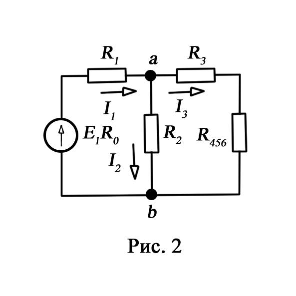
Consider an electrical circuit, the circuit of which is shown in Fig. 1. Let the resistor values be known R 1 , R 2, R 3 , R 4 , R 5 , R 6 , er d. E and its internal resistance R 0 . It is required to determine the currents in all parts of the circuit and the voltage that the voltmeter will show (its resistance is infinitely large) connected between the points of the circuit but and d.
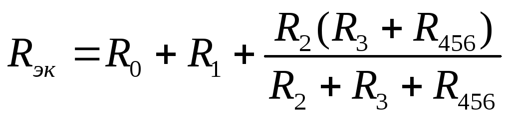
Such problems are solved by the method of coagulation of a circuit, according to which certain sections of the circuit are simplified and by gradual conversion they bring the circuit to one equivalent (input) resistance relative to the power supply terminals. The circuit is simplified by replacing a group of series-connected or parallel-connected resistors with one equivalent in resistance. So, resistors R 4 andR 5 are connected in series and the resistor R 6 - parallel with them, therefore their equivalent resistance
Where  .
.
After the transformations made, the circuit takes the form shown in Fig. 2, and we find the equivalent resistance of the whole circuit from the equation.
Current  in the unbranched part of the scheme we will define according to Ohm’s law: =
Using the scheme (Fig. 2), we find the currents  and
and 
 ;
;

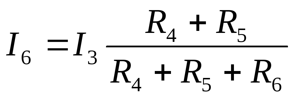
Turning to Figure 1, we determine the currents  ,
, and
and  according to similar equations:
 ;
;
Knowing current can find current
differently. According to the second Kirchhoff law,  ,
then
,
then 
The voltmeter reading can be determined by making an equation according to the second Kirchhoff law, for example, for the circuit acda:
 To test the solution, you can use the first Kirchhoff law and the power balance equation, which for the circuit shown in Fig. 1, will take the form
 ;
;
 ;
;
Electrical circuits with a single source can be calculated by the method of similarity (proportional magnitude method), which is applicable only to the calculation of linear circuits, i.e. circuits with constant resistance values. We use the properties of linear circuits to determine the currents of the circuit shown in Fig. 1, in the following order: set by an arbitrary current value  in resistor
  ,
most remote from the power source. For a given current and resistor resistance
determine the voltage
,
most remote from the power source. For a given current and resistor resistance
determine the voltage  .
.
;
 ;
;
 ;
;
Finally, we find the value of emf.  :
. However, the found value of e. d.
in general, it differs from the specified value of e. d.
:
. However, the found value of e. d.
in general, it differs from the specified value of e. d.  . Therefore, to determine the actual values of currents and voltages, we calculate the so-called similarity coefficient
  .
Multiplying the values of currents and voltages obtained by calculating it, we find the actual values of the circuit currents. The proportional magnitude method is especially effective when calculating branched linear single-source electrical circuits.
.
Multiplying the values of currents and voltages obtained by calculating it, we find the actual values of the circuit currents. The proportional magnitude method is especially effective when calculating branched linear single-source electrical circuits.

Methods of general analysis of linear electric circuits with multiple sources
An important issue in this section is the calculation of the distribution of currents in complex linear circuits with several sources. The classical method of calculating such chains is directkirchhoff law enforcement. All other methods of calculation are based on these fundamental laws of electrical engineering.
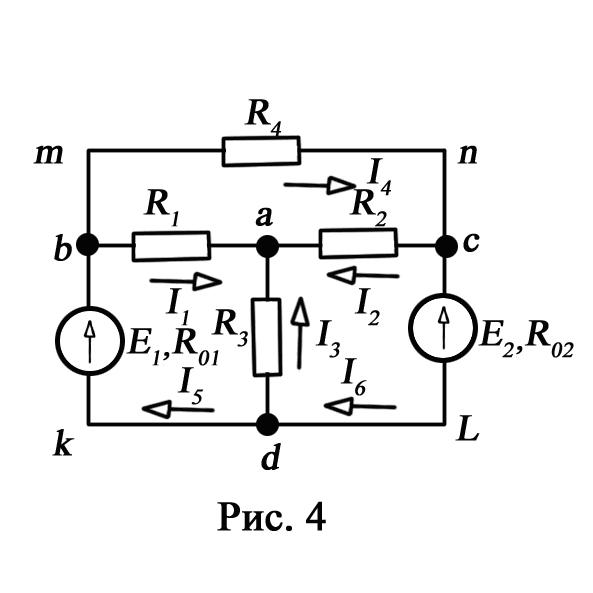
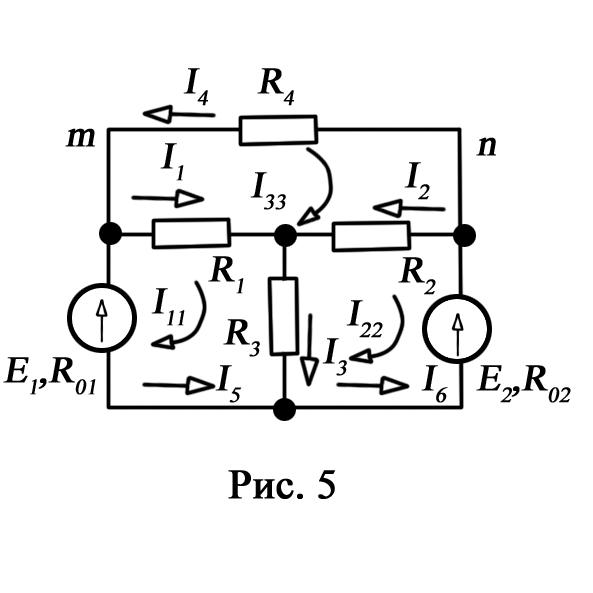
Consider a complex electrical circuit (Fig. 4), which contains six branches. If values of all are given. d. and resistances of resistors, and according to the condition of the problem it is required to determine the currents in the branches, then we have a problem with six unknowns. Such problems are solved with the help of Kirchhoff's laws. In this case, as many equations as unknown currents should be compiled. The calculation procedure is as follows.
If a chain contains serial and parallel connections, then it is simplified, replacing these connections by equivalent ones.
Randomly indicate the direction of currents in all branches. If the accepted direction of the current does not coincide with the actual, then in the calculation such currents are obtained with minus signs.
Make up (p-1) equations according to the first Kirchhoff law ( n- the number of nodes).
Missing Equations in Quantity t-(P-1) where t- the number of branches, constitute the second law of Kirchhoff, while the circuit can be traversed both clockwise and against it. For positive e. d. and currents are accepted such, the direction of which coincides with the direction of the circuit bypass. Direction of action e. d. inside the source always take from minus to plus (see fig. 4)
The resulting system of equations is solved with respect to unknown currents. Let's make the calculated equations for the electric circuit depicted in (Fig. 4.) By choosing arbitrarily the direction of the currents in the branches of the circuit, we make up the equations according to the first Kirchhoff law for a, b, s:
 (1)
(1)

Accepting the direction of the circuit bypassing clockwise, we make up the equations according to the second Kirchhoff's law for three arbitrarily chosen circuits:
for contour adkba
(2)
for contour bacldkb
(3)
for contour bmncab
(4)
Solving together equations (1), (2), (3) and (4), we determine the currents in the branches of the electrical circuit.
It is easy to see that the solution of the resulting system of six equations is a very laborious operation. Therefore, when analyzing electrical circuits with multiple sources, it is advisable to apply loop current method (cell method), allowing to reduce the number of jointly solved equations compiled according to two Kirchhoff laws by the number of equations written according to the first Kirchhoff law. Consequently, the number of equations compiled by the method of loop currents is equal to t-n + 1.When solving this method, the number of equations is determined by the number of cells. A cell is a circuit in which there are no branches. In this case, there are three such contours-cells: badkb, aclda, mncabm.
The calculation of complex electrical circuits by the method of loop currents is carried out as follows.
1. Introducing the concept of "loop current", we arbitrarily set the direction of these currents in the cells. It is more convenient to point all currents in one direction, for example, clockwise (Fig. 5).
2. For each contour-cell we compose an equation according to the second Kirchhoff law. We make a circuit around clockwise:
first circuit
second circuit
(6)
third circuit
(7)
Solving together equations (5), (6), (7), we determine the contour currents. In the case when the loop current is obtained with a minus sign, this means that its direction is opposite to that chosen on the scheme.
The currents in the internal branches of the circuit are defined as the sum or difference of the corresponding loop currents. In the case when the contour currents in the branch coincide, they take the sum, and when they are directed towards each other, they subtract the smaller one from the larger current.
Full-text search:
Main\u003e Abstract\u003e Physics
1.7. Calculation of electrical circuits using the laws of Ohm and Kirchhoff
Ohm and Kirchhoff's laws are used, as a rule, when calculating relatively simple electrical circuits with a small number of circuits, although in principle they can be used to calculate arbitrarily complex electrical circuits.
When calculating electrical circuits, in most cases, the parameters of sources of electromotive force or voltage, resistance of elements of an electrical circuit are known, and the task is reduced to determining the currents in the branches. Knowing the currents, you can find the voltage on the circuit elements, the power consumed by individual elements and the whole circuit as a whole, the power of the power sources, etc.
Calculation of a circuit with a single power source
The electrical circuit whose circuit is shown in Fig. 1.25, consists of a single power source having EMF E and internal resistance r 0, and resistors R 1, R 2, R 3, connected to the source according to a mixed circuit. It is recommended to perform operations for calculating such a scheme in a certain sequence.
1. Designation of currents and voltages in the circuit sections.
The resistor R 1 is connected in series with the source, so the current I 1 for them will be common, the currents in the resistors R 2 and R 3 we denote respectively I 2 and I 3. Similarly, we denote the voltage on the circuit.
2. Calculate the equivalent resistance of the circuit.
Resistors R 2 and R 3 are connected in parallel and replaced according to (1.7) with equivalent resistance:
![]() .
.
As a result, the chain in fig. 1.25 is converted into a circuit with series-connected resistors R 1, R 23 and r 0. Then the equivalent resistance of the entire circuit is written in the form:
R e = r 0 + R 1 + R 23
3. Calculation of current in the source circuit. The current I 1 is determined by Ohm’s law (1.2):
4. Calculation of voltages in the circuit sections. According to Ohm's law (1.1) we define the magnitude of the stress:
U 1 = I 1 R 1; U 23 = I 1 R 23
The voltage U at the terminals ab of the power supply will be determined according to the second Kirchhoff law (1.4) for circuit I (Fig. 1.25):
E = I 1 r 0 + U; U = E - I 1 r 0.
5. Calculation of currents and power for all sections of the circuit. Knowing the magnitude of the voltage U23, we define the Ohm law currents in the resistors R 2 and R 3:
According to the formula (1.8), we determine the amount of active electrical power given by the power source to consumers of electrical energy:
In the circuit elements consumed active power:
The internal resistance r 0 of the power source consumes part of the electrical power supplied by the source. This power is called the power loss:
6. Check the correctness of the calculations. This test is performed by compiling the power balance equation (1.8): the power supplied by the power source must be equal to the sum of the power consumed in the resistive circuit elements:
In addition, the correctness of the calculation of currents can be checked by making an equation according to the first Kirchhoff's law (1.3) for the circuit node:
I 1 = I 2 + I 3.
Calculation of an extensive electrical circuit with multiple power sources
The main method of calculation is the method of direct application of the first and second laws of Kirchhoff.
As an example, consider a circuit whose circuit is shown in Fig. 1.26. The circuit diagram contains 6 branches (m = 6) and 4 nodes: a, b, c, d (n = 4). Each branch has its own current, therefore the number of unknown currents is equal to the number of branches, and to determine the currents, it is necessary to make m equations. In this case, according to the first Kirchhoff law (1.3), they form equations for (n – 1) nodes. Missing m– (n – 1) equations are obtained according to the second Kirchhoff law (1.4), composing them for m– (n – 1) mutually independent contours. It is recommended to perform settlement operations in a specific sequence.
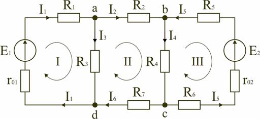
1. Designation of currents in all branches. The direction of the currents is chosen arbitrarily, but in circuits with sources of EMF, it is recommended that the direction of the currents coincide with the direction of the EMF.
2. Compilation of equations according to the first Kirchhoff law. Choose 4–1 = 3 nodes (a, b, c) and write the equations for them:
node a: I 1 - I 2 - I 3 = 0;
node b: I 2 - I 4 + I 5 = 0;
node c: I 4 - I 5 + I 6 = 0.
3. Formulation of equations according to the second Kirchhoff law. It is necessary to make 6–3 = 3 equations. In the diagram in fig. 1.26 choose contours I, II, III and write equations for them:
circuit I: E 1 = I 1 (r 01 + R 1) + I 3 R 3;
circuit II: 0 = I 2 R 2 + I 4 R 4 + I 6 R 7 - I 3 R 3;
circuit III: -E 2 = -I 5 (r 02 + R 5 + R 6) - I 4 R 4.
4. Solving the resulting system of equations and analyzing the results. The resulting system of six equations is solved by known mathematical methods. If, as a result of the calculations, the numerical value of the current is obtained with a minus sign, this means that the real direction of the current of this branch is opposite to that adopted at the beginning of the calculation. If in the branches with EMF the currents coincide in direction with the EMF, then these elements work in the mode of sources, giving energy to the circuit. In those branches where the directions of the current and the emf do not match, the sources of emf work in the consumer mode.
5. Check the correctness of the calculations. To check the correctness of the calculations made, on the basis of Kirchhoff's laws, we can write equations for the nodes and contours of the scheme, which were not used when compiling the initial system of equations:
node d: I 3 + I 6 - I 1 = 0
outer contour of the circuit: E 1 - E 2 = I 1 (r 01 + R 1) + I 2 R 2 - I 5 (r 02 + R 5 + R 6) + I 6 R 7.
An independent test is the compilation of the power balance equation (1.8) taking into account the modes of operation of circuit elements with an EMF:
If the active power supplied by the power sources is equal in magnitude to the active power consumed in the passive elements of the electrical circuit, then the correctness of the calculations is confirmed.
1.8. Basic methods for calculating complex electrical circuits
Using the laws of Ohm and Kirchhoff, in principle, it is possible to calculate electrical circuits of any complexity. However, the solution in this case may be too cumbersome and time consuming. For this reason, for the calculation of complex electrical circuits, more rational calculation methods have been developed based on the laws of Ohm and Kirchhoff, two of which, the nodal voltage method and the equivalent generator method, are discussed below.
Nodal stress method
It is recommended to use this method if a complex electrical circuit can be simplified by replacing series and parallel connected resistors with equivalent ones, using the conversion of a resistance triangle into an equivalent star if necessary. If the resulting circuit contains several parallel-connected active and passive branches, such as, for example, the diagram in Fig. 1.27, then its calculation and analysis can be very simply performed using the nodal tension method.
Neglecting the resistance of the wires connecting the branches of the circuit, in its scheme (Fig. 1.27) we can distinguish two nodes: a and b. Depending on the values and directions of EMF and voltages, as well as the values of the resistances of the branches between the nodal points a and b, a certain nodal voltage U ab will be established. Suppose that it is directed as shown in Fig. 1.27, and known. Knowing the voltage U ab is easy to find currents in all branches.
Choose the positive directions of the currents and denote them in the diagram. Let us write the equations according to the second Kirchhoff law for contours (1.4) passing through the first and second branches containing sources of emf, making a circuit around the contours clockwise.
The first branch: E 1 = I 1 (r 01 + R 1) + U ab.
The second branch: -E 2 = -I 2 (r 02 + R 2) + U ab.
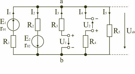
Fig. 1.27
Determine the values of currents that occur in the first and second branches,
 ,
,
 ,
,
where:  ;
;
 - conductivity of the first and second branches, respectively.
Let us write the equations according to the second Kirchhoff's law for the branches (1.5) containing the sources of voltages, making a detour of the contours also clockwise.
The third branch: U ab - U 1 + I 3 R 3 = 0.
The fourth branch: U ab + U 2 - I 4 R 4 = 0.
Determine the values of currents that occur in the third and fourth branches,
 ,
,
![]() ,
,
where:; - conductivity of the third and fourth branches, respectively.
The current in the fifth branch will be determined by Ohm's law:
 ,
,
where is the conductivity of the fifth branch.
To derive a formula for determining the voltage U ab, we write the equation according to the first Kirchhoff’s law (1.3) for node a:
I 1 - I 2 + I 3 - I 4 - I 5 = 0.
After replacing the currents by their expressions (1.20) - (1.24) and the corresponding transformations, we obtain
 .
.
The formula for the nodal voltage in the general case is
 .
.
When calculating the electrical circuit by the nodal voltage method, after determining the voltage U ab, the values of currents in the branches are found by their expressions (1.20) - (1.24).
When writing formula (1.25), the positive direction of the nodal voltage U ab should be set. With the “+” sign, (1.25) should include the EMF directed between points a and b opposite to the voltage U ab, and the voltage of the branches directed according to U ab. The signs in the formula (1.25) do not depend on the direction of the currents of the branches.
When calculating and analyzing electrical circuits using the nodal voltage method, it is recommended to select the positive current directions after determining the nodal voltage. In this case, when calculating currents using expressions (1.20) - (1.24), the positive directions of the currents can be easily chosen in such a way that they all coincide with their real directions.
Verification of the calculations made is carried out according to the first Kirchhoff law for node a or b, as well as compiling the power balance equation (1.8).
Equivalent Generator Method
The method of equivalent generator allows a partial analysis of the electrical circuit. For example, determine the current in any one branch of a complex electrical circuit and investigate the behavior of this branch when its resistance changes. The essence of the method lies in the fact that in relation to the amb branch under study (Fig. 1.28, a), the complex circuit is replaced by an active two-terminal circuit A (see fig. 1.23), the equivalent circuit of which is represented by an equivalent source (equivalent generator) with EMF E e and internal resistance r 0e, the load for which is the resistance R of the amb amb.
If the EMF and resistance of the equivalent generator are known, then the current I in the amb branch is determined by Ohm’s law
We show that the parameters of the equivalent generator E e and r 0e can be determined respectively by the modes of idling and short circuit of the active two-port.
In the scheme under study (Fig. 1.28, a), we introduce two sources, the emf of which E 1 and E e are equal and directed in different directions (Fig. 1.28, b). In this case, the value of the current I in the amb branch does not change. Current I can be defined as the difference of two currents I = Ie - I 1, where I 1 is the current caused by all sources of the two-port A and EMF E 1 (Fig. 1.28, c); I e - current caused only by the EMF E e (Fig. 1.28, d).
If you choose EMF E 1 of this size to get in the circuit (1.28, c) a current I 1 = 0, then the current I will be equal (Fig. 1.28, d)
 ,
,
where r 0e is the equivalent resistance of the two-pole device A relative to the terminals a and b.

Since when I 1 = 0 (Fig. 1.28, c), the active two-terminal network will work relative to the amb branch in idle mode, then the idle voltage U = U xx will be established between terminals a and b and for the second Kirchhoff law we get for amba E 1 = I 1 R + U xx = U xx. But by the condition E e = E 1, therefore, E e = U xx. Given this, the formula for determining the current I can be written in this form:
 .
.
In accordance with (1.26) the electrical circuit in fig. 1.28, and can be replaced by an equivalent circuit (Fig. 1.28, d), in which E e = U xx and r 0e should be considered as parameters of some equivalent generator.
The values of E e = U xx and r 0e can be determined both by calculation and experimentally. For the computational definition of U xx and r 0e, it is necessary to know the parameters of the elements of the active two-port and the scheme of their connection.
To determine the value of r 0e, it is necessary to remove all sources from the two-pole circuit, retaining all resistive elements, including the internal resistances of the EMF sources. The internal resistances of the voltage sources are assumed to be zero. Then calculate the equivalent resistance with respect to the conclusions of ab by known methods.
To determine the value of E e, open the circuit and determine the voltage U ab = U xx = E e between the pins ab of the active two-pole device using the nodal voltage method.
Experimentally, the parameters of an equivalent generator can be determined from the results of two experiments. Having opened a branch with resistance R (Fig. 1.28, d), we measure the voltage between the terminals a and b U ab = U xx = E e (idle experience).
To determine r 0e, a short circuit experience is carried out (if it is permissible): the specified branch is short-circuited and the short-circuit current I kz is measured in it. According to Ohm’s law, we calculate the value r 0e = E e / I kz.
|
License |
Model.Exponenta.Ru |
© N.V. Klinachyov, 1999-2008. All rights reserved. 800x600.