
![]()


Our capabilities
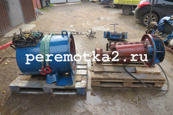
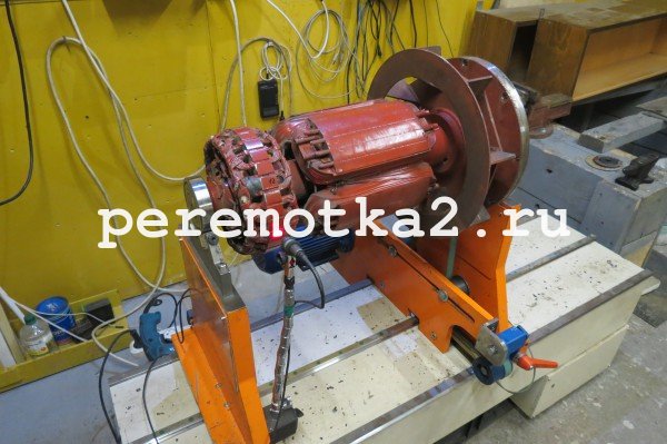
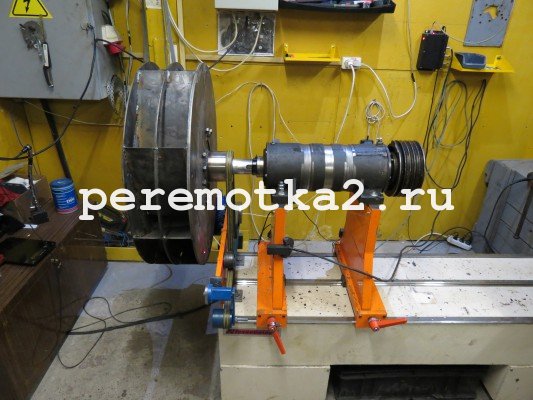
Dynamic balancing of vertical and horizontal rotors and shafts
Balancing in own supports at the Customer's enterprise
Balancing on machines
Diagnosing the causes preventing balancing
Identification of the causes of equipment failure
Result of equipment balancing
Reduction of vibration and increased loads
Longer service life of bearings, couplings and seals
Reducing the likelihood of equipment failure
Reducing electricity consumption
After balancing, all results are drawn up in the form of a balancing protocol, reflecting the name of the equipment, accuracy class, geometric parameters, tolerance field, as well as the initial and final imbalance levels.
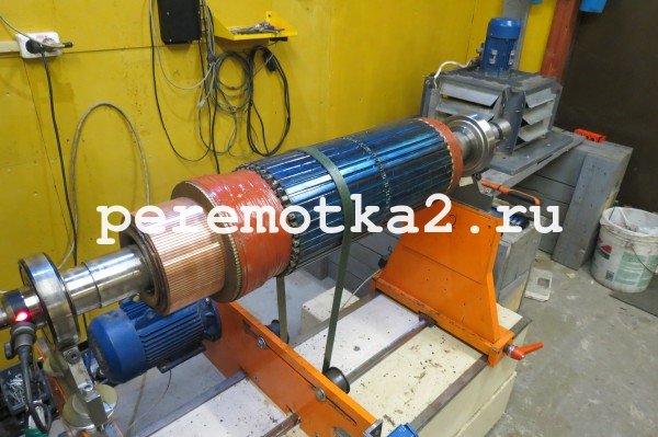
Balancing steps
Initial vibration measurement
Installing a test weight with a known mass
Re-measurement of vibration
Calculation of the corrective weight and the angle to the installation Installation of the weight on the rotor (or metal removal)
New vibration measurement before the result is achieved
Benefits of working with us
EXPERIENCE IN DEVELOPMENT AND RESEARCH SINCE 1985
Our engineers and scientists have been engaged in development and research in the field of vibration diagnostics for more than 30 years.
CERTIFIED NON-DESTRUCTIVE TESTING LABORATORY
The certificate of the non-destructive testing laboratory is a guarantee that the company has reliable equipment and professional specialists. Based on this document, we are able to give recommendations on the repair and maintenance of machines.
FREE DIAGNOSIS AND DETAILED REPORT
After balancing, you will receive a detailed report with the results "BEFORE" and "AFTER". And also with recommendations for further repairs and maintenance.
OWN DEVICE PRODUCTION
We develop vibration diagnostic devices ourselves and use them in our work.
Our Balancing Videos:

Balancing
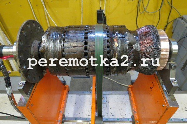
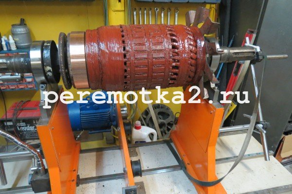
In machines with rotating mechanisms, the rotor and armature are subject to a mandatory procedure - balancing. It can be static and dynamic. Balancing of motor shafts is carried out on special equipment, while anchor imbalance is detected. He then becomes the main cause of the beating (vibration) on the shaft. Electric motor shaft balancing
The designs of the motor shafts combine a large number of elements in which the masses are distributed unevenly. The reasons for this unevenness can be:
* The difference in the masses of parts;
* Difference of elements in thickness;
* Departure of winding parts;
* Unbalance of parts due to inertial reason or displacement of their axes.
The mass of the individual parts of the assembled shaft is summed up or compensated, it all depends on the position of the individual components. If on the shaft, the axis of rotation is deviated from the axis of inertia, then such a shaft is called unbalanced. A shaft with such a characteristic during rotation will cause vibration phenomena, which will adversely affect the bearings of the motor and the base of the machine unit.
Work such as balancing shafts should be done in a specialized company. The service must have a staff of highly qualified craftsmen capable of performing this task quickly and efficiently. This is the kind of company our team is! We have a wealth of experience and are well versed in electric motors of all makes and models. If you need to balance the motor shaft, we will do this work using the most modern balancing equipment. Dial the phone number indicated on the site and our specialists will contact you and resolve all issues related to balancing.
Remember! Properly performed shaft balancing is the key to trouble-free operation of your equipment!
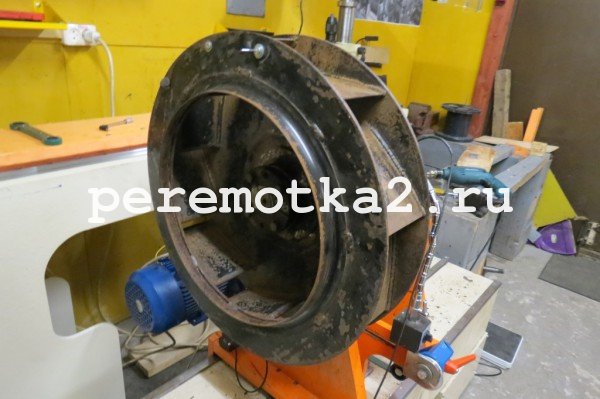
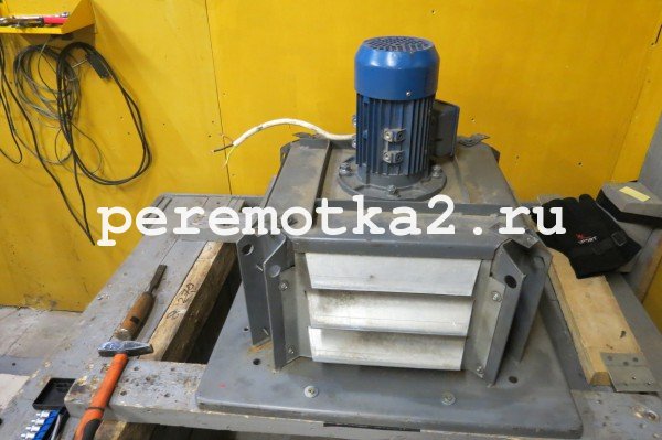
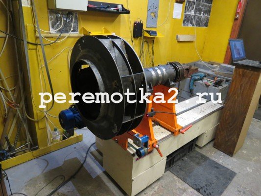
Motor ventilation balancing
Dynamic balancing of the motor ventilation system is one of the many operations performed to keep the rotating machinery running smoothly. Such balancing is carried out either on special balancing machines or on the engine's own mounts.
Why is ventilation balancing done?
All rotating mechanisms, as well as their elements separately, are subject to balancing. In case of poor-quality balancing, the engine may begin to vibrate, make noise, lose power, increase electricity or fuel consumption. This leads to failure of individual parts of the electric motor or its entirety.
When an asymmetry occurs in a rotating system (shift of the axis of rotation) or, in other words, an imbalance, troubles immediately arise due to an increase in vibration. The higher the rotation speed, the more pronounced the manifestations of imbalance become.
The service - "balancing the ventilation system", is provided by our company! In our state only highly qualified specialists are able to perform this task quickly and efficiently.
If you want to pay as little as possible for the repair of electric motors, then you must follow the operating rules for these devices:
* Balance motor ventilation must be done in a timely manner;
* Constantly monitor the health of the equipment;
* The electric motor must be operated with parameters corresponding to the technical passport of the unit;
* Increased vibration phenomena lead to additional loads on the entire engine or its individual parts.
If you need balancing of the ventilation system of the electric motor, then dial the phone number listed on our website. We will perform this work efficiently and on time, and after balancing the ventilation, the engine will work properly for many years!
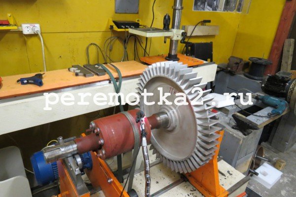
Motor rotor balancing
If parts of the machine with rotating parts are not balanced, then there is a possibility that the machine will start to vibrate. Vibration of the rotor, for example, can lead to failure of the entire device or its individual elements. For stable and correct operation of the engine, the balancing of the rotor is necessary.
Our company offers the service "Rotor balancing on a machine in Moscow". We perform this work efficiently and quickly. The electric motor after balancing the rotor will work without failure for a long time.
There are two types of work in this direction: static and dynamic balancing rotor. Static balancing is performed on prisms, while dynamic balancing is performed on a rotating shaft. In any case, you need a highly professional, experienced master who will do the job according to all the rules. It is also necessary to have special equipment (machines).
Before starting the dynamic balancing of the electric motor rotor, its surface and parts are checked for the absence of vibrations in them. If such phenomena are detected, then the specialist eliminates them in the first place. To perform high-quality balancing, according to the rules, there should be no loose elements on the shaft. Next, the motor shaft is placed in machine bearings, and the part to be balanced is set in rotation.
It makes no sense to describe in detail the entire procedure, since this is a very responsible and time-consuming task. Balancing the rotor yourself is very problematic. To balance the rotors of engines, special machines are needed, and most importantly, comprehensive knowledge of the rules for performing balancing and extensive experience in carrying out this work. Therefore, in a situation where balancing of the rotor of an electric motor is required, we advise you to contact a specialized company.
Do you need to balance the motor rotor? Dial our phone number listed on the site and we will perform all the work quickly and efficiently, and give the electric motors a new long life!
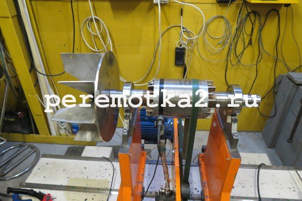
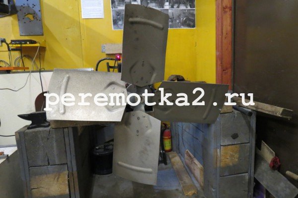
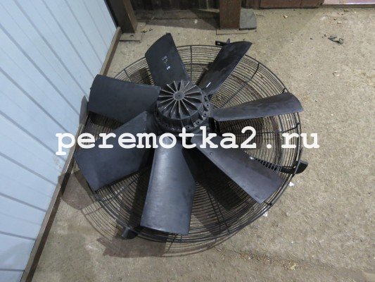
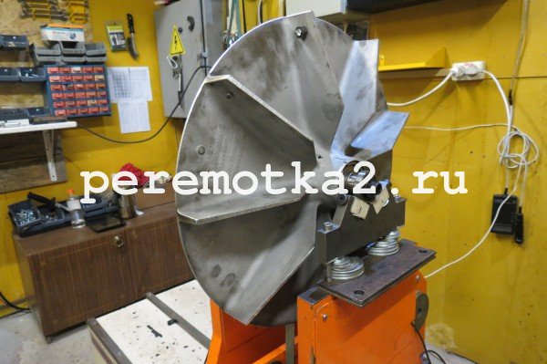
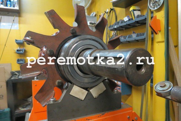
Motor fan balancing
When an increased runout is detected when diagnosing an engine fan for vibration, this may be due to several factors:
* Faults in coupling halves;
* Defects in impeller bearings;
* Defects in the foundation and foundation frame;
* Loose fastening of individual elements;
* Imbalance of the impeller;
* Mismatch of motor and fan axes;
* Imbalance of the motor shaft and some other phenomena.
As we can see, there are quite a few reasons for the occurrence of vibration. It is known from practice that the most common problem that causes beating is the imbalance of the fan elements. To eliminate such malfunctions, the fan impeller is balanced and the fan blades are balanced.
An unbalanced fan can cause the following problems:
* Reduced performance;
* The occurrence of noise;
* Rapid development of bearings;
* Wear of fingers of couplings of connection and consolidations;
* The appearance of defects in the foundation and others.
In addition to the rebalancing procedures mentioned above, the fan impeller is also balanced to eliminate signs of vibration and ensure smooth engine operation.
Our company performs fan impeller balancing efficiently and quickly. In order to order the service, just dial the phone number listed on our website. Our highly qualified specialists will contact you and advise you on all issues, including those related to fan blade balancing.
By performing a full balancing of the electric motor fan, you will achieve its long and uninterrupted operation, as well as save money on repairs in the future!
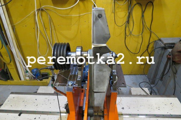
Motor pulley balancing
To transmit rotational movements, a long-established one is used - transmission using a belt. It is widely used in many units and various mechanisms. An important point in the maintenance of this type of gear is not only the alignment, but also the balancing of the pulleys of electric motors, each pulley separately.
You can balance the pulley using the static balancing method, since the pulley is nothing more than a certain kind of rotor. In a pulley, due to its shape, static imbalance plays a large role.
Sometimes, when the operating speeds of the pulley are high enough, dynamic balancing is also required, which is performed in one correction plane, excluding pulleys with several grooves. Multi-ribbed pulleys are balanced in 2 planes. Only a balancing specialist can determine what kind of balancing needs to be performed.
You can balance the pulleys yourself, but this requires experience and certain skills, as well as the availability of special equipment. Therefore, it would be more rational to do the balancing in a specialized company that has qualified specialists in its staff. Masters of such a service will perform balancing of pulleys efficiently and quickly. In addition, the client will receive a guarantee for the work performed.
Our company provides high-quality service "Balancing of pulleys of electric motors". This work is done by experienced craftsmen. After balancing, the engine will work for a long time and smoothly. Dial the phone number listed on our website! We will contact you, advise on all issues related to balancing pulleys and we will be able to perform this work with high quality!
Balancing of rotating parts
Our organization is engaged in dynamic balancing of ventilation systems, motor anchors, pulleys, shafts, impellers and other rotating parts both on their supports and on balancing machines.
What is balancing for?
Balancing is a native word for both a car and any other equipment with rotating parts. All rotating parts are subjected to this operation. Flywheel, crankshaft, clutch, cardan shafts, wheels, pulleys, fans, etc. Do not list everything. And it’s worth cheating here, as the imbalance will immediately announce itself with soul-exhausting shaking, vibrations, noises, rapid wear of bearings, loss of power, increased electricity consumption or fuel consumption, etc. Which leads to premature wear and breakage of other parts, and in some cases and all equipment.
An imbalance occurs if the rotating system is even slightly asymmetric. It is worth slightly shifting the axis of rotation from the center of the part or making this part even a fraction of a millimeter non-circular (or simply non-uniform in density) - an imbalance with its companions shaking, vibrations and wear is right there. It manifests itself, however, with an increase in the rotation speed. For example: at a speed of 100 km / h and an imbalance of 15-20 g on a 14-inch wheel, the load on the disk will be similar to hitting it with a three-kilogram hammer with a frequency of 800 times per minute.
And so the conclusion!
1. If you want to pay less and less often for repairs, follow the rules for operating industrial equipment. Get your balance right.
2. The equipment must be in good working order, and the parameters of its operation must comply with the technical data sheets. Rotating machine components (shafts, pulleys, fans, etc.) must be balanced both as individual parts and as an assembly.
3. Vibration of parts causes additional loads on the part itself and on the parts associated with it.
GOST 12.2.003-91 SSBT. Production equipment. General safety requirements
1.1. Production equipment must ensure the safety of workers during installation (dismantling), commissioning and operation, both in the case of autonomous use and as part of technological complexes, subject to the requirements (conditions, rules) provided for by the operational documentation.
Note. Operation includes, in general, the intended use, Maintenance and repair, transportation and storage.
2.1.2. The design of production equipment must exclude, in all intended modes of operation, loads on parts and assembly units that can cause damage that poses a danger to workers.
2.1.11. The design of the production equipment driven electrical energy, should include devices (means) to ensure electrical safety.
2.1.13. Production equipment that is a source of noise, ultrasound and vibration must be designed so that noise, ultrasound and vibration under the specified conditions and operating modes do not exceed the permissible levels established by the standards.
The rotor as a whole may have an uneven distribution of metal by weight relative to the axis of rotation and its center of gravity will not be located on this axis, i.e. by weight, the rotor will be unbalanced relative to the axis of rotation. This imbalance of the rotor or its parts is called imbalance.
When the rotor rotates, the unbalance causes the appearance of a radially directed perturbing force. This force tends to pull the shaft together with the part mounted on it from the bearings. The perturbing force changes its direction all the time, remaining radial, therefore its action on the bearings is variable in direction; such an action inevitably leads to vibration of the mechanism.
During vibration, parts of the mechanism experience shocks, shocks and overload, which causes accelerated general wear, violation of centering and fastenings, and this, in turn, further enhances vibration.
To eliminate the disturbing force, the rotor is balanced, i.e. correct its imbalance. Operations to correct the imbalance are called balancing. You can balance each part of the rotor individually or the entire rotor as a whole; the latter method is more economical and more accurate.
To balance the unbalance of the rotor, it is necessary at the same distance from the axis (where the unbalance is detected), but in the diametrically opposite direction, to weld (hang) the load of the mass necessary for balancing; after which the rotor will be balanced and no perturbing force will arise during its rotation.
The magnitude and location of the unbalance are found when performing various kinds balancing.
Distinguish static and dynamic rotor balancing:
1. Static balancing is called because the rotation of the rotor is not required to detect and eliminate unbalance; balancing is achieved when the rotor is at rest.
2. Dynamic imbalance is observed when the unbalanced masses of the rotor give two perturbing forces that are the same in magnitude, but oppositely directed and located at different ends. In this case, it may turn out that the common center of gravity of the rotor is located on the axis of rotation, i.e. the rotor is statically balanced. Such an imbalance can be detected only during the rotation of the rotor, since the common center of gravity of the rotor is located on its axis, and only during rotation do both unbalanced masses form a pair of perturbing forces of alternating direction. Therefore, a statically balanced rotor may in some cases be dynamically unbalanced. The operation to identify and eliminate dynamic imbalance is called dynamic balancing.
Installation of smoke exhausters
Smoke exhausters (D) are designed to suck flue gases from the boiler furnace and release them under pressure through the chimney into the atmosphere.
Smoke exhausters are centrifugal (1) and axial (2) type.
1. For boilers with a steam capacity of 420-640 t / h, centrifugal double-suction exhausters of the type: D-25x2Sh and D 21.5x2 are used.
These smoke exhausters consist of the following main components:
Bearings
Guide vanes and their drives
The installation of a smoke exhauster begins with the acceptance of the foundation and the installation of an electric motor on it.
Significant dimensions D double suction predetermine their delivery for installation in disassembled form. Therefore, the initial installation operation is the assembly of support structures D (frames) and volute bodies with suction pockets at the assembly site.
Installation D begins with the installation of a support frame, which is attached to the foundation with bolts. The frame is installed on metal pads, the total thickness of which can be up to 25-30 mm, with the number of pads in one package not more than three.
Linings are located on both sides of each foundation bolt and regulate the height marks, the deviation of which from the design ones is allowed no more than + - 6 mm.
Bearings D are installed on the support frame, the centering of which is carried out along the string and plumb lines.
After installing the bearing housings, housing D is installed on the foundation, then its rotor is laid.
Following the installation of housing D, control gates are mounted on its suction side. Pre-gates are audited, during which the smoothness of their opening and closing is checked.
The assembled D is tested at idle; in this case, radial and axial runouts of the impeller are allowed, respectively, no more than 3 and 6 mm.
2. In boiler plants with a steam capacity of 950 t / h and more, axial D type DO - 31.5 are used. The main advantages of these D (in comparison with centrifugal D) is their compactness. Two-stage axial D consists of:
suction pocket
Corps
guide vanes
impellers
Diffuser
Chassis
Oil pumping station with oil pipeline system
Ventilation for cooling
The suction pocket is made of two halves (upper and lower), connected on flanges. The total mass of the suction pocket is about 7.5 tons. It is installed on two foundation supports.
Building D is made of three parts designed to accommodate:
i. guide apparatus and impeller of the 1st stage;
ii. guide apparatus and impeller II stage;
iii. straightener.
All parts are connected to each other on flanges with bolts.
The chassis consists of a shaft, two bearings and a coupling connecting the shaft D with the electric motor.
Bearings D - roller type, spherical, self-aligning, running on liquid lubrication, which is supplied by the oil station through the oil lubrication system) (One oil station is installed on two Ds. Thermal protection of the support bearing installed in the diffuser housing is carried out using a special fan and a heat and sound insulating coating.
Installation D begins with the installation of supporting structures and the acceptance of the foundation. The concrete surface is preliminarily cleaned from irregularities and notched at the locations of the foundation bolts and pads for the supporting structures D. The pads are made of sheet steel with a width of 100-200 mm and a length corresponding to the width of the lower plane of the supporting structure. The number of linings should not exceed three in one place.
Technological sequence of installation ____ axial smoke exhauster DO - 31.5
| Priority | Knot | Main works |
| I | Lower body | Installation on supporting structures. Installation of longitudinal stop keys. Alignment of thermal gaps in the attachment points of the supports. |
| Thrust bearing | Installation and fixing on the foundation supporting structures thrust bearing and rotor in compliance with axial clearances. | |
| electric motor | Installation on the shafts of the coupling half. Installation of the frame and electric motor. | |
| Nodes 1,2,3 | Alignment of the main axes and height marks of the lower part of the body, chassis and electric motor. | |
| Chassis | Alignment of the lower part of the housing to the rotor in compliance with the radial clearances. | |
| Smoke exhauster housing supports | Pouring concrete for the foundation bolts of the hull footings. | |
| Platforms and stairs | Installation on the foundation drive guide vanes. Installation of scaffolds and ladders around the electric motor and smoke exhauster housing. | |
| Bottom of the suction pocket | Removing the blower rotor. Installation under- | |
| foundation rates. Lubrication of the supporting surfaces of the stands with a mixture of grease and graphite. Installation of the lower part of the suction pocket. | ||
| The lower part of the fairing (coca) | Installation of the lower part of the fairing and the lower cover of the protective casing of the thrust bearing. Rotor installation. | |
| Upper body | Installation of the upper part of the smoke exhauster housing on asbestos gaskets in a horizontal slot. Installing the upper part of the fairing. | |
| Bottom of the suction pocket | Final installation and fastening to the body of the lower part of the suction pocket. | |
| Safety devices | Installation of the protective casing of the support bearing and stuffing box seal. | |
| Guide vanes | Installation of swivel rings, levers, rods and drive guide vanes. | |
| Diffuser | Installing the diffuser pipe on a temporary support. Sequential installation of three sections of the diffuser. Installation of spacer ribs between the pipe and the cone of the diffuser. | |
| Cooling Fan | Installation of the cooling fan and air duct. | |
| Top of the suction pocket | Assembly of the upper part of the suction pocket, installation of the shaft guard | |
| Smoke exhauster and electric motor shafts | Alignment and connection of the shafts of the smoke exhauster and the electric motor. |
7-6. ROTOR BALANCE
If the rotating part of the machine is not balanced, then when it rotates, the whole machine shakes (vibrates). Vibration causes destruction of bearings, foundations and the machine itself. For elimination
vibration rotating parts must be balanced. Distinguish between static balancing, performed on prisms, and dynamic balancing when rotating the part to be balanced. If, for example, the rotor shown in Fig. 7-9, a, has a heavier half //, then during rotation the centrifugal force of this half will be greater than the centrifugal force of half /. It will create pressure on the bearings, variable according to
Rice. 7-9. Offset of the center of gravity of the rotor,
board, and cause the machine to shake. This unbalance is eliminated by static balancing on prisms. The rotor is placed with the shaft necks “and the prisms, precisely aligned horizontally, and at the same time, of course, turns the heavy side down. On the upper side, in special grooves, which are provided in the pressure washers and winding holders, lead weights of such weight are selected and placed so that the rotor remains in an indifferent position on the prisms. After balancing, lead weights are usually replaced with steel weights of the same weight, which are securely welded or screwed to the rotor. However for long armatures and rotors, static balancing is not enough. Even if you balance both halves of the rotor so that the weights of both halves are the same (Fig. 7-9.6), it may turn out that the centers of gravity are shifted along the axis of the machine. In this case, the centrifugal forces of the two halves cannot balance each other, but create a pair of forces that cause variable pressure on the bearings. To eliminate the action of this pair of forces, special weights must be placed (Fig. 7-9.6) in order to create a pair of forces acting inversely to a pair of unbalance forces. Find the magnitude and position of these
loads can be achieved by balancing the rotating rotor (dynamic balancing).
Before performing dynamic balancing, check the working surfaces of the rotor (necks and shaft ends, collector, slip rings, rotor steel) for the absence of runout and, if necessary, eliminate it. If to install the rotor on the machine,
Rice. 7-10. dynamic balancing scheme,
If any mandrels are hard, they should be checked for runout and unbalance.
There should not be loose parts on the rotor, since in this case balancing is impossible. For dynamic balancing, the rotor is placed in the bearings of a special machine. These bearings are mounted on flat springs and, if desired, can either be fixed motionless with a special brake, or freely oscillate together with the spring (Fig. 7-10, a). The rotor is driven by an electric motor and a clutch. The resulting unbalance force, which is directed radially, will rock the bearings of the machine. For balancing, one bearing is fixed by a brake motionless, the second is released and oscillates under the influence of unbalance. On any precisely machined surface of the rotor, concentric with the axis of the shaft, make a colored pencil mark showing the point of greatest deviation of the rotor (Fig. 7-10.6).
However, at this point it is not yet possible to accurately determine
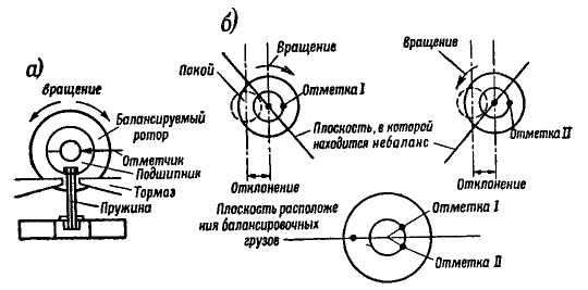
the place where the unbalance of the rotor is located, since the greatest deviation of the rotor is obtained after the passage of the unbalance force through the horizontal plane in which the marker (pencil) is located.
The shear angle (i.e. the angle between the point of unbalance and the mark) depends on the ratio of the rotation speed to the natural frequency of the oscillation of the rotor on the supports, i.e., to the frequency of oscillation that will occur if a non-rotating rotor mounted on the supports of the machine is pushed.
When the number of revolutions per second coincides with the natural frequency, resonance occurs. The fluctuations acquire the greatest scope and, consequently, the machine becomes the most sensitive. Therefore, they strive to balance at a resonant speed. In this case, the above angular shift becomes close to 90° and, therefore, the place of unbalance can be found by counting from the middle of the -90° mark forward in rotation (and the place of installation of the weight 90° against rotation). If for some reason it is impossible to work at the resonant speed, then to determine the location of the unbalance, the described experiment is repeated with the opposite direction of rotation at the same number of revolutions per mi-yutu. The mark is made with a pencil of a different color. Then the middle between the two marks determines the place where the unbalance is. A balance weight is installed at the diametrically opposite point. The value of this load is determined by selection until the vibration of the bearing disappears. Instead of strengthening the load, balancing can be obtained by drilling out the opposite side of the anchor. After one side of the rotor is balanced, the bearing of this side is fixed motionless, and the bearing of the second side is released and the other side is balanced in the same way. After that, the balance of the first side is checked and, if necessary, corrected, etc.
Currently, there are a large number of machines for dynamic balancing, on which the location and size of the load are determined quite conveniently and accurately. The operating methods for these machines are given in the manufacturer's instructions.
In the absence of special machines, dynamic balancing can be carried out on durable wood
dried beams laid on rubber pads. On these bars, either the shaft journals of the balanced rotor are placed directly, or the bearing shells in which the shaft journals lie. With the help of wedges, the bars can be fixed motionless. The rotor is rotated by a belt drive, covering directly the steel, then the wedge is removed, and the bearing is allowed to oscillate on rubber pads. The balancing process is similar to that described above.
In terms of repair, especially for large machines, it is advisable to balance the assembled [L. 8]; for this purpose, the machine is started idle and the vibration of the bearings is measured. This measurement should be made using vibrometers (for example, types VR-1, VR-3, 2VK, ZVK).
In the absence of vibrometers, vibration can be measured with an indicator mounted on a massive heavy handle. By pressing the probe of such an indicator to an oscillating part, it is possible to determine the magnitude of the oscillation amplitude by the width of the blurred arrow outline.
It should be borne in mind that the readings of such a vibrometer are strongly dependent on the speed of rotation and that therefore its readings can be used mainly as comparative ones at the same number of revolutions of the machine, which is sufficient for balancing purposes.
By measuring the vibration of the bearing in different directions, the point of greatest vibration is found. It is at this point that balancing is carried out.
To find the size and location of the balancing weight, a test weight is placed on the rotor at an arbitrary point and the vibration is measured again. It is obvious that, having studied how the test load, the size and location of which are known, affects the vibration, it is possible to determine both the magnitude of the unbalance and its location. If it is possible to measure how the magnitude and phase of the vibration change as a result of the installation of the test weight (see below), then two measurements can be dispensed with: before and after the installation of the test weight. If it is impossible to determine the phase change, then it is necessary to make a larger (3-4) number of measurements of the vibration magnitude. In this case, the test load is placed first at any arbitrary point, and then alternately at the points spaced by the Uz of the circle to the right and left of the first.
To determine the phase change, you can resort to the marks on the shaft, as described above. At the same time, the shaft is painted over with chalk and a sharp scriber (caution-“0) is applied (as short as possible) marks, the middle of which corresponds to the largest deviation of the shaft in the plane where the marker (scriber) is located. The angular distance (angle a) between the marks in the absence of a test load and in its presence is a measure of the phase shift of the oscillation due to the introduction of a test load.
More precisely, the phase shift is determined by a stroboscopic method. In this case, a mark is applied to the end of the shaft, illuminated by flashes of a gas-light lamp. This lamp is controlled by a special contact available h vibrometer, which closes 1 time per revolution of the shaft at a moment close to the largest oscillation amplitude.
The mark on the rotating shaft appears to be stationary (because the lamp illuminates it every time it is exactly in the same position after one revolution), and a mark can also be applied against it “and the stationary part of the machine.
After the introduction of the test load, the mark on the shaft is shifted relative to the mark on the fixed part. By making a second mark on the fixed part, corresponding to the new position of the mark on the shaft, and by measuring the angular distance (angle a) between them, we determine the angle of the oscillation phase shift.
The ability to determine the phase by stroboscopic method is provided in special balancing vibroscopes of the Kolesnik 2VK, ZVK system, manufactured by the Leningrad Tool Plant, and in vibroscopes of the BIP type of the Kyiv Electromechanical Plant
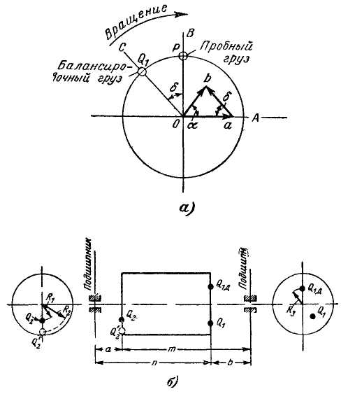
The graphical method for determining the location of the cargo is visible from fig. 7-11, a. Here the segment is a "vector" oa on a certain scale it is equal to the span of oscillation of the bearing before the introduction of a test load. Trial load R tr is placed in a plane shifted from the mark obtained at the same time on the shaft at some angle, for example 90 °, -line Oh V. Having measured now swing of the bearing (with the same number of revolutions per minute), marking a new label and having determined the angular shift between the marks - a, we now put it on the same scale at an angle "to the vector oa vector ob,
Obviously, if the vector oa depicts vibration from unbalance, vector ob vibration from the joint action of the trial load and unbalance, then the difference age. torus ab determines the magnitude and phase of the vibration caused by the test weight.
Figure 7-11 Determining the size and location of balancing weights
In order to eliminate vibration from unbalance, it is necessary to rotate the vector ab angle § and increase it so that it is equal to the vector oa and directed against him. Obviously, for this, the test load Р gr must be shifted from the point AT exactly FROM(by angle S) and increased in relation to segments ^-. Balance weight
i must therefore be equal to:
The second side of the machine is balanced in a similar way, but the load defined for this side Q "z distributed over two loads Q 2 and Q H . This is done in order not to upset the balance of the first side.
Cargo<2г помещается в точку, определенную описанным выше способом для второй стороны, а груз СЬ Д переносится на первую сторону и закрепляется в точке диаметрально противоположной Q 2 (рис.-7-11,6). Величины грузов Q 2 I am Qia are determined from the expressions:
where are the dimensions m, n, a, b, RiR^R 3 visible from Fig. 7-111, b. Despite this distribution of weight Q "2, it is usually necessary to perform (corrective) balancing again. The first side after the weights are installed Q2 and SY D.
The easiest way to check the quality of the balance is to place the machine on a smooth planed horizontal slab. If the machine is satisfactorily balanced, running at rated speed, it should not swing or move on the plate. The test is carried out at idle in engine mode.
The position of the axis of inertia of the rotor depends on the distribution of its elements around the circumference. If the masses of all assembly units and parts are evenly distributed, the axis of inertia coincides with the axis of rotation.
Such a rotor is called balanced. In most cases, the masses are distributed unevenly, the axis of inertia is shifted relative to the axis of rotation, an imbalance appears, equal to the product of the unbalanced mass and its eccentricity. Such a rotor is called unbalanced. In unbalanced rotors, centrifugal forces arise that are proportional to the imbalance and the square of the rotational speed.
Rice. 1. Types of imbalances:
a - static, b - dynamic, c - mixed
When the force is directed upward, the pressure on the bearing decreases, when the rotor rotates 180°, the force acts downward, increasing the pressure on the bearing.
Such a periodic change in pressure on the bearing leads to vibration of the rotor, which is transmitted through the bearing to the body and foundation of the machine, impairs the operation of the sliding contact and reduces the durability of the bearings.
Unbalanced rotors balance. The balancing process consists in combining the axis of inertia of the rotor with the axis of rotation by removing metal or installing balancing weights in certain places along the circumference of the rotor. The rotors of high-speed machines are especially carefully balanced.
There are three types of rotor unbalance: static, dynamic and mixed. With static unbalance, the axis of inertia A-A (Fig. 1, a), which passes through the center of gravity C, is shifted parallel to the axis of rotation of the rotor. In this case, the centrifugal force RCT from unbalance causes vibrations of the same magnitude and in phase on the supports. Dynamic unbalance is characterized by the location of the axis of inertia A-A at an angle to the axis of rotation (Fig. 1, b). In this case, a pair of centrifugal forces Ram causes vibrations of the same magnitude and opposite in phase on the supports. Mixed unbalance (Fig. 1, c) is reduced to a pair of forces Rn„„ and force RCT, the vibrations of the supports in this case differ both in magnitude and in phase. The most common is mixed unbalance.
There are two types of balancing: static and dynamic. For low-speed machines with a short rotor, they are usually limited to static balancing. For other machines, after static balancing, dynamic balancing is carried out.
With static balancing, the removal of metal or the installation of weights is carried out at one end of the rotor. In dynamic balancing, each half of the rotor is balanced separately.
Rotor 1 (Fig. 2, a) during static balancing is placed with the ends of the shaft on parallel horizontal rulers - prisms 3, set in level. The deviation from the horizontal level should not exceed 0.02 mm per 1000 mm of length. The width of the working surface of the prism is chosen depending on the mass of the rotor.
| Rotor weight, kg | from 30 to 300 |
from 300 to 2000 |
||
Prism working surface width, mm |
If the diameters of the shaft necks are not the same, to align the rotor axis, a ring 2 is installed on the neck with a smaller diameter, the thickness of which is equal to the difference in the radii of the necks. 
Rice. 2. Static balancing:
a - on prisms, 6 - on rotating supports
More accurate results are obtained by static balancing on rotating supports (Fig. 2, b) with rolling bearings. The diameter D and the length of the rollers 4 are selected depending on the mass of the rotor 1.
During static balancing, the rotor is rotated on prisms or supports, setting it in different positions. If the axis of inertia is located above the axis of the shaft, the rotor under the action of an unbalanced mass m (Fig. 2, a) begins to rotate and after several oscillations in one direction and the other stops. In this case, the unbalanced mass is in the lower position. The balancing weight is attached at the top of the rotor. Then the rotor is again installed in different positions, selecting such a mass of load at which the rotor stops rotating in any of its positions.
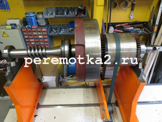
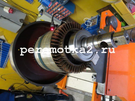
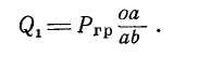
Dynamic balancing of the rotors is carried out on special machines, which allow determining the mass and position of the balancing weights in two correction planes * A and B (Fig. 3). Rotor 1 is placed in spring-loaded supports 2 and 9 of the machine and driven by an electric motor 7.
The vibrations of the supports, caused by the unbalance of the rotor, are transmitted to the coils 3, which move in a magnetic field between the poles N and S. An EMF arises in the coils, proportional to the amplitudes of the vibrations of the supports.
*Correction planes are called planes perpendicular to the base of rotation, in which the unbalance of the rotor is compensated by removing or adding masses. As planes of correction, planes of parts can be used - pressure washers, fans, manifolds or special parts - balancing rings.
The voltage from the coils through the amplifier 4 is supplied to the device b and to the stroboscope circuit 5. The flashes of the lamp 8 of the stroboscope illuminate the scale on the machine spindle. Flashes coincide in time with the maximum vibration displacement, i.e. with the moment when the unbalanced mass is in the upper or lower position. 
Rice. 3. The scheme of the balancing machine
The strobe flashes one instantaneous flash for every rotation of the rotor. whereby the rotating scale appears to have stopped at a certain position. The machine is stopped, the rotor is rotated to the position that was seen on the scale during rotation, thereby establishing the place where the test weight should be attached: the "light" and "heavy" places are located in a vertical plane. The unbalance of the rotor is determined by the pointer device 6. The machine is turned on again. If the weight is set correctly, the readings will decrease. By gradually increasing the load, the imbalance is eliminated. If the instrument reading increases, the load must be moved 180°. First, balancing is performed in one plane, for example, in plane A, connecting the left coil to the amplifier; then, with the help of a switch, a second coil is connected, balancing the second half of the rotor. The rotors of large machines balance in their own bearings when the machine rotates without load.
Vibration of bearings is measured by vibrometers or pointer indicators.
Three classes of balancing accuracy are provided for electric machines: zero, first and second. The second class of accuracy is set for machines with the usual requirements for the level of vibration, the first - for low-noise machines and machines with increased rotational accuracy (for machine tools, household appliances, etc.). Zero class is required for machines with particularly high vibration requirements; these machines use bearings of high accuracy classes, the rotor is balanced in the assembled machine, and windows are provided in the shields for access to the balancing points.
The rotor drawing indicates the planes of correction and methods for eliminating imbalance, as well as the permissible residual imbalance, since it is almost impossible to achieve complete balance of the rotor during the balancing process.
The balancing of the rotors must be carried out observing the following safety rules. When statically balanced on prisms, the rotor should be placed in the middle of the prisms and rotated slowly so that it does not fall when rolling. The length of the prisms must be such that the rotor can make at least one revolution in each direction. Before installing the rotor on the prisms, make sure that the length of the shaft is greater than the distance between the prisms. Rotating bearings are pre-checked for seizing in bearings. During dynamic balancing, do not stop the rotor by hand. Balance weights must be carefully secured. The sleeves of work clothing must be cuffed to prevent them from being caught by rotating parts.
The difference between static and dynamic balancing of parts, their purpose. Anchor balancing technology.
Unbalance of any rotating part of a diesel locomotive can occur both during operation due to uneven wear, bending, accumulation of contaminants in any one place, in case of loss of a balancing weight, and during repair due to incorrect processing of the part (shift of the axis of rotation) or inaccurate alignment shafts. To balance the parts, they are subjected to balancing. There are two types of balancing: static and dynamic.
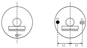
Rice. 1. Scheme of static balancing of parts:
T1 is the mass of the unbalanced part; T2 - weight of balancing weight;
L1, L2 - their distances from the axis of rotation.
Static balancing. In an unbalanced part, its mass is located asymmetrically relative to the axis of rotation. For this reason, in the static position of such a part, i.e. when it is at rest, the center of gravity will tend to take a lower position (Fig. 1). To balance the part, a load of mass T2 is added from the diametrically opposite side so that its moment T2L2 is equal to the moment of the unbalanced mass T1L1. Under this condition, the part will be in balance in any position, since its center of gravity will lie on the axis of rotation. Balance must also be achieved by removing part of the metal part by drilling, sawing or milling from the side of the unbalanced mass T1. On the drawings of parts and in the Repair Rules, a tolerance is given for balancing parts, which is called unbalance (g / cm).
Flat parts with a small ratio of length to diameter are subjected to static balancing: a gear wheel of a traction gearbox, a refrigerator fan impeller, etc. Static balancing is carried out on horizontally parallel prisms, cylindrical rods or on roller bearings. The surfaces of prisms, rods and rollers must be carefully processed. The accuracy of static balancing largely depends on the condition of the surfaces of these parts.
dynamic balancing. Dynamic balancing is usually applied to parts whose length is equal to or greater than their diameter. On fig. Figure 2 shows a statically balanced rotor, in which the mass T is balanced by a load of mass M. This rotor, when rotating slowly, will be in equilibrium in any position. In this case, with its rapid rotation, two equal, but oppositely directed centrifugal forces F1 and F2 will arise. In this case, a moment FJU is formed, which tends to rotate the rotor axis at a certain angle around its center of gravity, ᴛ.ᴇ. there is a dynamic imbalance of the rotor with all the ensuing consequences (vibration, uneven wear, etc.). The moment of this pair of forces must be balanced only by another pair of forces acting in the same plane and creating an equal counteracting moment. To do this, in our example, it is necessary to attach two loads with masses Wx = m2 to the rotor in the same plane (vertical) at an equal distance from the axis of rotation. The weights and their distances from the axis of rotation are selected so that the centrifugal forces from these weights create a moment /y counteracting the moment FJi and balancing it. Most often, balancing weights are attached to the end planes of the parts or a part of the metal is removed from these planes.
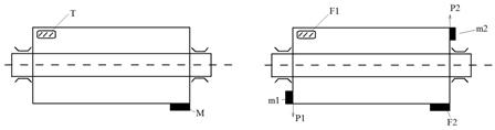
Rice. 2. Scheme of dynamic balancing of parts:
T is the mass of the rotor; M is the mass of the balancing load; F1,F2 - unbalanced, reduced to the planes of the mass of the rotor; m1,m2 - balanced rotor masses reduced to planes; Р1 Р 2 - balancing centrifugal forces;
When repairing diesel locomotives, such rapidly rotating parts as the rotor of a turbocharger, the armature of a traction motor or other electric machine, the impeller of the blower assembly with the drive gear, the shaft of the water pump assembly with the impeller and gear wheel, cardan shafts of the drive of power mechanisms are subjected to dynamic balancing.
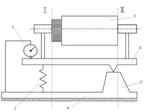
Rice. 3. Scheme of a cantilever type balancing machine:
1 - spring; 2 - indicator; 3 anchor; 4 - frame; 5 - machine support; 6 - bed support;
I, II-planes
Dynamic balancing is carried out on balancing machines. A schematic diagram of such a cantilever type machine is shown in fig. 3. Balancing, for example, the armature of the traction motor is carried out in this order. Anchor 3 is placed on the supports of the swinging frame 4. The frame rests at one point on the support of the machine 5, and the other on the spring 1. When the anchor rotates, the unbalanced mass of any of its sections (except for the masses lying in the plane II - II) causes the frame to swing. The oscillation amplitude of the frame is fixed by indicator 2. In order to balance the anchor in the I-I plane, test weights of various masses are attached alternately to its end face from the side of the collector (to the pressure cone) and the frame oscillations are stopped or reduced to an acceptable value. Next, the anchor is turned over so that the plane I-I passes through the fixed support of the bed 6, and the same operations are repeated for the plane II-II. In this case, the balance weight is attached to the rear thrust washer of the anchor.
After completion of all work on the acquisition, the parts of the selected kits are marked (letters or numbers) according to the requirements of the drawings
The difference between static and dynamic balancing of parts, their purpose. Anchor balancing technology. - concept and types. Classification and features of the category "The difference between static and dynamic balancing of parts, their purpose. Technology of balancing anchors." 2014, 2015.