Principle of work DPT.The vmashine should have two main parts: the first part - creates a magnetic flux, the second part - in which the EMF is induced. The first part in the DC machine is stationary. To the frame (1), the stamped poles (2) are mounted on which the excitation winding (3) is located. The second part is the anchor. Anchor rotates. It is a cylinder recruited from sheets of electrical steel (4). In the outer part of the armature there are grooves where the winding sections (5) are stacked. Each section is connected to the collector plates (6). 

An electrical circuit, called a generator, can be used to change the frequency. To create a simple generator circuit, connect the inductor in parallel with the variable capacitor. This field is attracted or repelled by a set of permanent magnets.
One way to adjust the supply voltage for the motor is by means of a voltage divider circuit. A simple voltage division control circuit can be implemented using a potentiometer. Connect the positive power terminal to one of the potentiometer terminals. Connect the negative power terminal to the other potentiometer cable. Connect the potentiometer cable to one of the motor terminals, and the other to the negative power terminal. If necessary, adjust the potentiometer to monitor the engine speed.
The electromagnetic moment depends on the current and the current of the armature. In the generator mode, the electromagnetic moment is inhibitory. The equation of the equilibrium state of the moments will be written, where is the mechanical moment on the generator shaft, the moment x, is the electromagnetic moment. Basic equation of motion of the electric drive. The steady state process, when ,,, If,. If,,. 
Development of a common electronic card for the control of three-phase motors. The overall design of the electronic board for controlling the 3-phase AC. Sanchez R. 7. Information about the article: received: February. This article presents the design and development of a power driver with a controller for an inexpensive three-phase motor and with a wide range of applications in the industry. The proposed handler consists of two stages: the first is a control stage in which a specialized microcontroller is included to control the motor, and the second is a power standard controlled by isolated gate transistors as switching elements.
 The principle of speed control. In terms of speed control, the DC motor is universal. You can adjust the speed by changing the resistance in the armature circuit, the flow and the voltage applied. This can be seen from the formula:.
This proposal is part of a project whose main objective is to offer a methodology that enhances the quality of electronic prototypes that are developed in the academic environment; so that they are more in line with the standards required by the industry, which facilitates communication between the university and industry in terms of technological cooperation in the field of automation and control.
Descriptors: energy manager, methodology, quality, prototypes, industrial standards, asynchronous motor. The first stage of control, which includes an induction motor controller, a specific microcontroller. This project is part of a wider project whose main goal is to improve the quality of the academy.
Resistance in the chain of the anchor.Equations of currents before and after the introduction of resistance
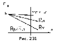
Whence, ie, the currents decrease (). With this, the speed decreases. As the speed of the anchor decreases, it will reach the initial armature current, but at a lower speed. The speed control of the resistance in the armature circuit is carried out in the direction of decreasing speed. 
It is expected that these prototypes will be harmonized with industry standards, which will allow the industry, the university connection for technological cooperation in the field of automation and management. Keywords: energy manager, methodology, quality, prototypes, industrial standards, motor induction.
Linking universities and research centers to the manufacturing sector is a topic that has been present in Mexico for more than a decade in the plans and plans for economic and social development offered by various federal and state governments. The purpose of this connection is to include and apply technological scientific knowledge in industrial production, so that it becomes the central axis of the companies' competitiveness.
Flow. The current of the armature before and after the flow change, their ratio. The equation 5.1. moments. We reduce the flow, the current of the armature increases, then, it (increases).
Stress.Speed regulation is performed in the following ways: A) Generator-motor system (GD). B) Thyristor converter-motor (TP-D). B) Pulse width regulation.
However, to date, there is a limited number of universities in Latin America for the transfer of technological developments in the industry. Some of these limitations are insufficient research capacity to offer technological solutions to the problems of manufacturing companies and ignorance of the quality requirements that technological development must meet in order to become competitive at the industrial level.
There are several research and development projects related to three-phase electric motors at the academic level. In projects developed by Latin American universities, commercial controllers, such as programmable logic controllers, are often chosen because they are widely known and reliable. However, this decision is inexpedient to implement in applications, the purpose of which is mass production at a low price.
 A) GD system, Fig.234. . Increasing the excitation current of the generator and increasing the flux of and, consequently, the voltage at the armature of the motor increases and the velocity increases.

Comparatively, the review of the state of the case revealed a small number of successful tools in proposals of academic origin. In one of them, the use of a commercial driver is notorious, the cost of which is 5 times greater than that of the engine used.
In the work of Tsu and Hsu, it would be interesting to carry out a cost analysis that proves that this solution is a viable option for mass production. This work originated at the request of the manufacturer to develop a prototype power management device with a controller for a three-phase motor. It was considered expedient to use methodologies that guarantee satisfaction of the client's requirements.
B) Thyristor converter-motor. By increasing the control angle - the half-cycle area decreases, the average value of the voltage -U cp decreases, and consequently the speed of rotation decreases.
B) Pulse width regulation.
Changing the pulse time t and changing the duty cycle, where t and - the pulse time; t n is the pause time. The average value of U cp = U 0 . . 
The methodology used is based on the conceptualization of the process of designing and building an electronic prototype according to the scheme of coordinated interaction between the controller and the controlled subsystem. The customer needs to operate a three-phase motor in his application. This type of engines requires little maintenance, in addition to the market demand, which requires more and more devices with better performance.
To control three-phase motors in conjunction with the client application, sophisticated control algorithms are required, which are implemented through a microcontroller, which allows processing signals in real time. Working conditions of the map: ambient temperature and heat generated by the components.
6. Methods of adjusting the active and reactive power of a synchronous machine.
Methods for controlling the active and reactive power of a synchronous generator. As soon as we saw that if we change the excitation of the generator, then we will change the reactive power, give, or consume. The active power can only be adjusted by changing the mechanical power from the side of the steam turbine or the turbine. When increasing the output power, it is necessary to increase the mechanical power from the turbine side.
Simplicity of repair and maintenance, this consideration directly affects the density of the chains and the position of the components. Test requirements that may affect the position of the components, the routing of tracks and the assignment of connectors. Some considerations are to avoid electromagnetic interference.
There are some very simple considerations to reduce the time and cost of finding defects. For example, the orientation of the polarized parts or components must be consistent so that the designer does not confuse the components oriented 180 ° in phase with respect to the others. Unpolarized components must have a fully identified terminal number 1, so that the operator performing the tests has a reference to that particular pin that needs to be checked.
Start the SD. To start a synchronous motor, it is necessary to accelerate its rotor by means of an external torque to a speed close to synchronous. In view of the absence of a starting torque in the synchronous motor, the following methods are used to start it: 1 Start by means of an auxiliary motor; 2Aynchronous start of the motor.
1. Start-up of the synchronous motor with the aid of an auxiliary motor can be made only without a mechanical load on its shaft, i.e. almost idle. In this case, during the starting period, the engine is temporarily converted into a synchronous generator whose rotor is driven into rotation by a small auxiliary engine to n = 0.95n 1. The stator of this generator is connected in parallel to the network in compliance with the conditions of this connection. After the stator is turned on, the excitation winding is turned on, and the motor is pulled into synchronism, and the auxiliary drive motor is mechanically switched off. This starting method is complicated and has, in addition, an auxiliary motor.
Therefore, for this prototype, from the logical and schematic approach, the integration of two phases, the stages of control, whose main task is to provide the basis for executing algorithms for controlling the engine speed and torque, as well as the power stage, whose main task is the condition of signals that will flow directly to the engine, in accordance with the control algorithm used. In addition, considering the requirements for the size of the map and considerations of the working environment, ease of maintenance and repair and production costs, the design of the two-layer prototype was considered.
2. The synchronous motor is converted into an asynchronous motor for the duration of the start-up. For the possibility of forming an asynchronous starting torque in the grooves of the pole pieces of a pole pole motor, a short-circuit starting winding is placed. The process of starting a synchronous motor is carried out in two stages. When the stator winding (1) is turned on, a rotating field is generated in the motor, which will guide the short-circuited winding of the rotor (2) of the EMF. Under the action, which will flow in the bars current. As a result of the interaction of the rotating magnetic field with the current in the short-circuited winding, a torque is created, as in an asynchronous motor. Due to this moment, the rotor accelerates to a slip close to zero (S = 0.05), Fig. 313. This concludes the first stage. To make the motor rotor retracted into synchronism, it is necessary to create a magnetic field in it by inserting a direct current into the excitation coil (3) (by switching key K to position 1). Since the rotor is accelerated to a speed close to synchronous, the relative velocity of the stator and rotor fields is small. The poles will seamlessly find each other. And after a series of slips, the opposite poles will be attracted, and the rotor will retract into synchronism. After that, the rotor will rotate at a synchronous speed, and its rotation speed will be constant, Fig. 313. This concludes the second stage of the launch. Operation of the LED under unexcited and overexcited modes (ib=
var).
The operating mode corresponds to the constancy of the torque. at. In the case of a non-excited synchronous motor, the component of the voltage-E 0 corresponds to the current I, which lags behind the voltage Uc by an angle φ. The reactive component of the current I L will lag by 90 0 from the voltage vector Uc, i.e. this current is purely inductive. This means that, under underexcitation, the motor will draw an inductive current from the network, and consequently will consume reactive power from the network. 
Figure 1 shows a block diagram of the handler. A good grounding scheme provides a return of DC power and, in addition, a reference plane for high-speed AC signals. On the other hand, the impedance loop of the decoupling capacitor is minimized so that its connectors are as small as possible and put them in a chain in the correct order, next to the circuit of interest.
On the other hand, it is recommended that the assignment of signals to the terminals of the device be related to the ground signal. No type of isolation was realized, as including them would lead to an increase in the cost of mass production of the prototype. Customer requirements establish that there is no need to know the direction of rotation, but only to ensure that this changes and that the final application uses a hall effect sensor to know the engine's rotation speed.
As the excitation increases, the quantity -E 0 1 increases, and the current I decreases to Ia = I 1 and will be minimal. In this mode, the LED will work with cosφ = 1 and reactive power, will not be consumed, nor given to the network. With a further increase in the excitation current, the voltage component will be -E 0 11, and the current I 11, will advance the grid voltage vector by an angle φ 1. This mode corresponds to an overexcited mode. The reactive component of the current will be capacitive (leads the vector Uc by 90 0). This mode will correspond to the return of reactive power to the network. This mode is similar to the inclusion of static capacitors in the network. 

The supply voltages for the control and power stages were kept constant and within the desired operating ranges. The signals of the three-phase signal of an unloaded motor are shown in the form in which two phases can be seen. A prototype of the main power driver with a controller for a three-phase motor was obtained. The tests carried out were mainly focused on checking power signals and control stages for power supplies and adapting feedback signals to provide a reliable card that can serve as a basis for testing more complex asynchronous motor control algorithms, eliminating the uncertainty of possible failures caused by poor electronic design .
So we see that if you change the excitation current iB, then the value of the stator current I will vary in magnitude and phase, i.e. it is possible to adjust cosφ. This is a valuable property and determines the use of synchronous motors. Dependences of the stator current I on the excitation current iB, I = f (iв) are called U-shaped characteristics, Fig. 309. P 2\u003e P 1. The characteristics are removed for P = const. The operating mode corresponding to the excitation current from 0 to the dotted line is underexcited, and behind the dotted line is the overexcited with reactive energy supplied to the network.
The relevance of the prototype is that its design and construction have been carried out by applying an industry standard for extended use that will allow in future work to apply quality assurance methods, development and implementation of a test plan and verification, through which it will also be possible to identify hidden design errors , work and a pass when fulfilling customer requirements and implementing proposals to improve the performance and cost of the proposed card.
The use of standards allows at a later stage to develop a test and verification plan, as well as relevant documentation in the development of prototypes developed in the academic environment. The above is important not only because it facilitates the transfer of this technology, minimizing the uncertainty in communication between users and suppliers, but also because it allows in measurable terms to determine the levels of safety, efficiency and repeatability of the prototype.
There are in the electrical installations positions, when without an electric motor, working on direct current, can not do. It is this electric motor that can be regulated by the speed of rotation of the rotor, which is required in electrical installations. True, he has a lot of flaws, and one of them is a quick wear of the brushes, if their installation was conducted with curvature, and the period of their operation is quite low. When there is wear and tear, there is sparking, so this engine can not be used in explosive and dusty rooms. Plus, the DC motor is expensive. To change this situation, use an asynchronous motor and a frequency controller for an asynchronous motor.
In addition to increasing the confidence of users in the prototypes provided by the academic sector, the use of a formal methodology teaches the engineering students the skills and abilities necessary to stimulate technological innovation.
Modeling and assembling a prototype for the management and navigation of mobile robbery, in: Conference of Electrical and Electronic Engineering. Technological Institute of Costa Rica, School of Electronic Technology. Modern control for rotating electric machines and automated systems. Development and construction of an automated didactic module for starting and reversing the control of a three-phase asynchronous motor and a single-phase power generation system.
Virtually all indicators of electric motors running on alternating current, surpass analogues on a permanent basis. First, they are more reliable. Secondly, they have smaller dimensions and weight. Third, the price is lower. Fourth, they are easier to operate and connect.
But the disadvantage they have one is the difficulty in regulating the speed of rotation. In this case, the standard methods for controlling the frequency of induction motors are not suitable here, namely, voltage changes, resistance setting, and so on. The frequency control of an asynchronous electric motor was the number one problem. Although the theoretical basis has been known since the thirties of the last century. The whole matter rested on the high cost of the frequency converter. Everything changed when they invented the microcircuits, through which it became possible through the transistors to assemble a frequency converter with a minimum cost.
Principle of regulation
Thus, the method for controlling the speed of an induction motor is based on a single formula. Here it is below.
ω = 2πf / p, where
- ω is the angular velocity of rotation of the stator;
- f is the frequency of the input voltage;
- p is the number of pole pairs.

That is, it turns out that the speed of rotation of the electric motor can be changed only by changing the frequency of the voltage. What does this give in practice? The first is smooth operation of the motor, especially it will feel when starting up the equipment, when the engine itself runs under the highest loads. The second is increased slip. This increases the efficiency, and the loss of power characteristics is reduced.
The structure of the frequency regulator
All modern frequency converters are built on the principle of the so-called double conversion. That is, the alternating current is converted to a constant through an uncontrolled rectifier and filter. Further, through the pulse inverter (it is three-phase), an inverse transformation of the current into an alternating current occurs. The inverter itself consists of six power switches (transistor). So each winding of the electric engine is connected to certain rectifier keys (positive or negative). It is the inverter that changes the frequency of the voltage, which is applied to the stator windings. In fact, it is through it that the frequency control of the electric motor occurs.
In this device, power transistors are installed at the output. They act as keys. If we compare them with thyristors, then it should be noted that the first produce a signal in the form of a sinusoid. It is this form that creates minimal distortion.
Now the very principle of the frequency converter. To understand this, we suggest to disassemble the picture below.
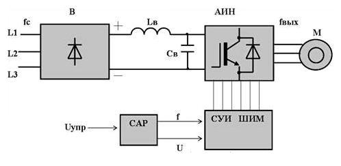
So, let's go through the drawing, where
- "B" is an uncontrolled power diode rectifier.
- "AIN" is an autonomous inverter.
- "SUI PWM" is a system of pulse-width control.
- "SAR" is an automatic control system.
- "Sv" is the filter capacitor.
- "L" - the throttle.
Under the scheme it is very clear that the inverter regulates the frequency of the voltage due to the system of pulse-width control (it is high-frequency). It is this part of the regulator that is responsible for connecting the stator windings of the electric motor alternately to the positive pole of the rectifier, then to the negative pole. The frequency of connecting to the poles occurs on a sinusoidal curve. In this case, the pulse frequency is determined precisely by the PWM frequency. This is how frequency regulation occurs.