Russian State Pedagogical
University.
abstract
on computer architecture
on the topic:
“Fiber Optic Networks”
Performed: YunchenkoT.
student II of course
Faculty of IOT, group 2.2
Checked:
Power Specifications
Sidebar: what is the nature of light. Light is a series of electromagnetic waves with several properties of particles injected. The first characteristic of light is color. Some bright red, some blue, etc. after several years of research, scientists have discovered that each color of light has its own wavelength; or, in other words, its own frequency. For example, the waves of red light have a lower frequency than blue light, and green - somewhere in the middle.
Fiber Optic Transmission
Our eyes perceive different frequencies of light waves, for example, radio receivers, at different frequencies of radio waves. Instead of indicating the light by its frequency, we denote color by the wavelength of light. Thus, a certain wavelength of light means a certain color of light. We measure wavelengths in nanometers, which make up billionths of a meter. For example, deep red light would have a wavelength of about 600 nm.
St. Petersburg 2004
1. Optical cable device
2. Optical Fiber Classification
3. Fiber Optic Transmission
4. DWDM and traffic
5. DWDM tomorrow
6. Literature
Fiber Optic Networks and TechnologyDWDM
Optical cable device
The main element of an optical cable (OK) is an optical waveguide - a round rod of an optically transparent dielectric. Optical waveguides due to their small cross-sectional dimensions are commonly referred to as optical fibers (BC) or optical fibers (OM).
The wavelength and frequency really mean the same thing, and you can replace them using a mathematical equation. We determine the wavelength, not the frequency, since the former is usually easier to use and finds in most scientific publications.
There is also such a thing as invisible light; but this light is not actually invisible. It has a wavelength outside the human visual range. Shortwave signals are waiting for you, but your receiver cannot tune to them. A good example of invisible light is infrared light, which is the type of light that our television remote control uses. Invisible light is what we use in optical fibers for transmitting signals. It would be convenient to use visible light, but it just does not work well.
The dual nature of light is known: wave and corpuscular. Based on the study of these properties, quantum (corpuscular) and wave (electromagnetic) theories of light have been developed. These theories cannot be contrasted. Only in their totality they allow us to explain the known optical phenomena.
An optical fiber consists of a core through which light waves propagate and a cladding. The core serves to transmit light waves. The purpose of the shell is to create the best reflection conditions at the “core-shell” boundary and protection from the radiation of energy into the surrounding space.
These wavelengths are outside our visual spectrum in the infrared. Fiber optics is a set of technologies that allow to transmit signals from two-point in the form of light instead of electricity. The main component is an optical fiber, a thread made of glass material that carries an optical signal. The two related components are: a light emitting diode and its advanced cousin, a semiconductor diode laser that converts electrical signals into optical signals and connects them to the fiber; and a photodiode that receives optical signals from the fiber and converts them back into electrical signals.
In the general case, three types of waves can propagate in an OF: directed, flowing, and radiated. The action and the predominance of any type of waves are associated primarily with the angle of incidence of the wave on the “core-shell” interface. At certain angles of incidence of the rays on the OB end, the phenomenon of total internal reflection takes place at the “core-shell” boundary. Optical radiation is locked in the core and spreads only in it.
Although fiber optics has many applications, including its use in sensors, it has the greatest impact on telecommunication technologies. For thousands of years, people have used optical technology to transmit signals over a distance, for example, in the form of smoke puffs, reflected sunlight or flares. Remember the hero of the American Revolutionary War, Paul Revere, and a warning signal: “One, if by land and two, if by sea?” But these methods are limited to what people can see within the final line of sight. wireless electrical technology provides a global, even interplanetary transfer.
Optical Fiber Classification
Distinguish between single-mode and multimode modes of radiation transmission by optical fiber. In the multimode mode of propagation of radiation along the fiber, the condition of total internal reflection is fulfilled for an infinite set of rays. This is possible only for agents whose cores are much larger than the length of the propagated waves. Such agents are called multimode.
But these technologies have high attenuation, high susceptibility to noise and low bandwidth. Although coaxial cable helps alleviate these problems, fiber optics provide better point-to-point media than any form of wired electronics.
The diameter of an optical fiber is usually only one eighth of a millimeter, but the ankle fiber is rarely seen. When it is covered with protective plastic, a single fiber looks like an insulated wire. Or many fibers are included in the cable which includes an internal plastic spine for strength and stiffness and a rigid outer sheath that protects the fibers from external damage.
In single-mode optical fibers, unlike multimode, only one beam propagates, and, therefore, signal distortion caused by different propagation times of different rays is absent.
All agents are divided into groups according to the type of propagating radiation, into subgroups according to type - according to the type of profile of the refractive index, and into types - according to the material of the core and the shell.
See what "Optical communication" is in other dictionaries
Optical fiber is uneven in cross-section. The concentric cylindrical area, called the “core”, lies inside the fiber. The core has a slightly different chemistry from the outer layer of fiber called “plating”. Light launched into the fiber core moves the fiber length, while remaining inside the core, ricochets from its walls.
When an electrical signal moves along a wire, individual electrons move slowly, moving from atom to atom. But optical signals are transmitted by photons that are triggered into the fiber and carry a signal as the fiber passes. Electrical signals travel along a wire or coaxis at a bandwidth-dependent speed, usually around 20 percent of the speed of light. While optical signals and electrical signals in free space move at the speed of light, light moves more slowly in glass than in air.
There are the following groups of agents:
Multimode (M)
Single mode without saving polarization of radiation (E)
Single-mode with preservation of polarization of radiation (P)
The group of multimode OBs are divided into two subgroups:
With stepped refractive index (C)
With gradient index of refraction (G)
In addition, agents are divided into the following types:
Thus, optical signals cross fibers at about two-thirds of the speed of light, which is three times faster than electrical signals move along wires. In a multimode fiber, different angles of a ricochet have different speeds, so a narrow optical pulse propagates as it moves. In a more expensive single-mode fiber, a smaller core diameter supports only one mode, which eliminates this modal distortion and allows the pulses to be more closely spaced, providing a higher data transfer rate.
Quartz core and shell
The core is quartz, and the shell is polymer
Multicomponent core and shell
Polymer core and shell
To destination optical communication cables are divided into:
Urban
Zonal
Trunk
Depending on the conditions of installation, stationary and linear optical cables are distinguished. The latter, in turn, are divided into cables intended for laying in sewers and collectors, ground, for suspension on supports and racks, for underwater installation.
Since different wavelengths have slightly different speeds, even single-mode pulses can propagate. The use of a light source with a narrow range of wavelengths reduces this effect, known as chromatic dispersion, which makes it possible to even more closely break the pulses, which leads to an even higher data transfer rate. Many long-haul commercial optical fibers today have 5 gigabits per second, and new transmitters and receivers support 10 Gbit / s on top of the same fiber.
World numbers and glass
A process called time division multiplexing interleaves individual signals. Another technology, called wavelength division multiplexing, has recently become practical. These wavelengths should be far enough from each other to be practically separable at the receiver, but close enough to each other to be inside windows with a fiber attenuation wavelength.
Fiber Optic Transmission
If to compare with other methods of information transfer, the order of TB / s is simply unattainable. Another advantage of such technologies is the reliability of the transmission. Transmission over fiber does not have the disadvantages of electrical or radio signal transmission. There are no interferences that could damage the signal, and there is no need to license the use of radio frequencies. However, not many people are aware of how information is transmitted over fiber in general, and even more so they are not familiar with specific implementations of technology. We will consider one of them - technology DWDM (dense wavelength-division multiplexing).
Fiber optics are highly non-linear. When analog signals are transmitted over a fiber, the fiber cannot be brought to limits. Thus, modern transmission is digital, because digital signals are not so subject to nonlinearity. The maximum interval of any transmission line is determined by the signal-to-noise ratio at the receiver. Increasing the length of the wire increases both the received noise power and the signal attenuation. The property that holds the optical signal inside the fiber core also keeps external interference outside it.
First, consider how information is transmitted over fiber. Optical fiber is a waveguide through which electromagnetic waves with a wavelength of the order of a thousand nanometers (10-9 m) propagate. This is an area of infrared radiation that is not visible to the human eye. And the basic idea is that with a certain selection of fiber material and its diameter, a situation arises when for some wavelengths this medium becomes almost transparent and even when it hits the boundary between the fiber and the external environment, most of the energy is reflected back inside the fiber. This ensures that the radiation passes through the fiber without any special losses, and the main task is to receive this radiation at the other end of the fiber. Of course, such a brief description hides the huge and difficult work of many people. Do not think that such material is simply created or that this effect is obvious. On the contrary, this should be treated as a great discovery, as now it provides the best way to transfer information. It is necessary to understand that the waveguide material is a unique development and the quality of data transmission and the level of interference depend on its properties; The waveguide insulation is designed to minimize the energy output to the outside.
Thus, fiber lengths can be longer than wire spans. Different wavelengths not only have different speeds, but also have different attenuation. The practical attenuation required for a short range of optical fiber requires that the wavelength of the light source be in the infrared range from 7 to 6 microns. The very low attenuation required over a long period of time occurs in two narrow wavelength regions: about 3 and 5 microns, where the light sources are expensive.
The lowest attenuation occurs at 5 μm, but the chromatic dispersion is minimized at a distance of 3 μm. It is not surprising that long-distance optical transmission occurs between these two wavelengths. Despite the low attenuation and low noise immunity, the most important characteristic of the fiber is its wide bandwidth. Comparing the transfer of information with the flow of water, the bandwidth corresponds to the diameter of the pipe. Researchers are just starting to figure out how to use it all.
As for the technology specifically called “multiplexing,” this means that you are simultaneously transmitting several wavelengths. They do not interact with each other, and when receiving or transmitting information, interference effects (the imposition of one wave on another) are insignificant, since they are most pronounced at multiple wavelengths. Here we are talking about the use of close frequencies (the frequency is inversely proportional to the wavelength, so it doesn’t matter what to say). A device called “multiplexer” is an apparatus for encoding or decoding information into a wave format and vice versa. After this brief introduction, we will proceed to the specific description of the DWDM technology.
For high speeds on long spans where singlemode fiber and semiconductor diode lasers are to be used, fiber optic communication is expensive. But the huge bandwidth makes it cost-effective. While fiber material is cheaper than wire, fiber is more expensive to produce, especially single-mode fiber. However, since the new installation cost is usually.
Much higher than the cost of what is being established, it is common practice to incorporate dark fiber into any wired installation, even if there are no current plans for it. There are other problems with costs. Fiber optics are more difficult to use than wire, and technicians need to be trained. While the wire may be soldered or wrapped around the terminal, the optical fiber must be carefully spliced. Fiber connectors, especially for single-mode fiber, are more expensive than wired connectors.
The main characteristics of DWDM multiplexers, which distinguish them from just WDM multiplexers:
using only one transparency window of 1550 nm, within the EDFA nm amplification area (EDFA is an optical amplification system; EDFA is an optical repeater, it allows you to recover the optical signal power lost when passing along a long line without conversion to an electrical signal and vice versa. Optical fiber doped with rare earth elements erbium, has the ability to absorb light of one wavelength and emit at another wavelength. An external semiconductor laser sends infrared light with a length of 980 or 1,480 millimicron waves, energizing erbium atoms. When an optical signal with a wavelength of 1530 to 1620 millimicron enters the fiber, excited erbium atoms emit light of the same wavelength as the input signal. and reduces the cost of amplifying equipment and makes it possible not to introduce additional distortions during transformations. EDFA amplifiers are used on “long-range” lines where it is difficult to install complex intermediate amplifying equipment (for example, submarine cable). For reference, let's say that the wavelength of visible light is 400-800 nm.
Users access information signals on multiple competing media. People access commercial television signals using a local antenna, coaxial or direct dish, and point-to-point applications, such as telephony or Internet service provider connections, wired or local wireless networks. But the infrastructure highways that distribute these signals across broad areas use the application-dependent selection environment. Commercial television is broadcast efficiently using geosynchronous satellites, and broadband networks for point-to-point applications, such as long-distance networks for telephony and the Internet for data, typically use fiber optics.
In addition, since the name itself speaks of dense (dense) channel transmission, the number of channels is greater than in conventional WDM schemes and reaches several dozen. Because of this, there is a need to create devices that are able to add a channel or extract it, in contrast to conventional schemes, when encoding or decoding of all channels occurs at once. The concept of passive wavelength routing is associated with such devices operating with one channel of many. It is also clear that working with a large number of channels requires greater accuracy of signal encoding and decoding devices and places higher demands on the quality of the line. Hence the obvious increase in the cost of devices - while reducing the price for the transfer of a unit of information due to the fact that it can now be transferred in a larger volume.
This is how the demultiplexer works with the mirror (the diagram in Fig. 1a). The incoming multiplex signal goes to the input port. This signal then passes through a waveguide plate and is distributed over a number of waveguides, which are an AWG (arrayed waveguide grating) diffraction structure. As before, the signal in each of the waveguides remains multiplexed, and each channel is represented in all waveguides, that is, only parallelization has occurred. Then the signals are reflected from the mirror surface, and as a result, the light fluxes are again collected in the waveguide plate, where they focus and interfere. This leads to the formation of an interference pattern with spatially separated maxima, and usually the calculation of the geometry of the plate and the mirror is made so that these maxima coincide with the output poles. Multiplexing occurs in reverse.
This can all change, of course, as technology, industry, applications, and economics evolve. Despite technical feasibility, the use of fiber optic cables and fiber optic networks is economically difficult to justify. If video conferencing becomes popular, it may be the so-called “golden service” that makes this possible.
Because of the non-linearity that causes the light to move faster through the illuminated fiber than the dark fiber, the photons at the back of the pulse can actually catch up with the photons from the front. A soliton is an impulse whose form is retained because this effect carefully balances the effects that broaden the impulses, and the researchers are trying to make them practical. With all this untapped potential bandwidth, fiber optics is a logical technology for creating networks that need to scale easily, like the Internet.

Fig. 1. Schemes of DWDM multiplexers: a) with a reflective element; b) with two waveguide plates
Another way to build a multiplexer is not based on one, but on a pair of waveguide plates (Fig. 1b). The principle of operation of such a device is similar to the previous case, except for the fact that an additional plate is used for focusing and interference.
DWDM multiplexers, being purely passive devices, introduce a large attenuation into the signal. For example, the losses for a device (see Fig. 1a) operating in the demultiplexing mode are 10–12 dB, with far crosstalk less than –20 dB and a signal spectrum half-width of 1 nm (according to Oki Electric Industry materials). Due to large losses, it is often necessary to install an optical amplifier before and / or after the DWDM multiplexer.
The most important parameter in the dense wave multiplexing technology is undoubtedly the distance between adjacent channels. The standardization of the spatial location of the channels is needed, if only because it will be possible to begin tests for the mutual compatibility of equipment from different manufacturers on its basis. The Telecommunication Standardization Sector of the International Telecommunication Union ITU-T approved the DWDM frequency plan with a distance between adjacent channels of 100 GHz, which corresponds to a wavelength difference of 0.8 nm. The question of the transmission of information with a difference in wavelengths of 0.4 nm is also being discussed. It would seem that the difference can be made even smaller, thus achieving greater throughput, but this leads to purely technological difficulties associated with the manufacture of lasers that generate a strictly monochromatic signal (a constant frequency without interference) and diffraction gratings that share in space corresponding to different wavelengths. When using 100 GHz division, all channels uniformly fill the band used, which is convenient when setting up the equipment and reconfiguring it. The choice of the separation interval is determined by the required bandwidth, the type of laser and the degree of interference on the line. However, it should be borne in mind that when operating even in such a narrow range (nm), the influence of nonlinear noise at the boundaries of this region is quite significant. This explains the fact that with an increase in the number of channels it is necessary to increase the laser power, but this, in turn, leads to a decrease in the signal-to-noise ratio. As a result, the use of more rigid compaction has not yet been standardized and is under development. Another obvious drawback of increasing density is a decrease in the distance over which a signal can be transmitted without amplification or regeneration (more details will be given below).
Note that the above-mentioned problem of nonlinearity is inherent in amplification systems based on silicon. More reliable fluorine-zirconate systems are being developed, providing greater linearity (in the whole nm region) of the gain. As the EDFA workspace increases, it becomes possible to multiplex 40 channels of STM-64 at intervals of 100 GHz with a total capacity of 400 GHz per fiber (Fig. 2).
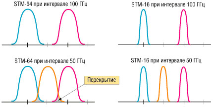
Fig. 2. Spectral placement of channels in the fiber
The table shows the technical characteristics of one of the powerful multiplex systems using a 100/50 GHz frequency plan, manufactured by Ciena Corp.
|
System level |
Capacity, Gbit / s |
channels of 2.5 Gbit / s) |
|
OC-48 / (STM-16) / OC-48c / STM-16c |
||
|
Frequency plan | ||
|
Possible configurations |
5 spans of 25 dB each - (500 km) 2 spans of 33 dB each - (240 km) |
|
|
System error rate (BER) | ||
|
Channel Interfaces |
Short / intermediate distances, STM-16 / G.957 I-16 & S.16.1, intra office applications |
|
|
Input Level, dBm |
from -18 to -3 |
|
|
Output level, dBm | ||
|
The wavelength of the input radiation, nm | ||
|
Network management |
Control system |
Wavewatch manufactured by CIENA via SNMP or TMN |
|
Standard interface |
VT100 (TM), asynchronous RS-232, remote access via Telnet, ITU TMN, TL-1, SNMP |
|
|
Channel health monitoring |
Channel bit errors through the B1 SDH header, monitoring the optical power in each channel |
|
|
Remote Interfaces |
RS-422 / X.25 (TL-1 interface), IP / 802.3 via 10Base-T |
|
|
Optical service channel |
2.048 Mbps at a wavelength of 1625 nm |
|
|
Power Specifications |
Supply voltage, V, DC |
from -48 to -58 |
|
Power consumption at 40 channels, W |
800 typical, 925 (maximum) - stand 1, 1000 typical, 1250 (maximum) - stand 2 |
Let us dwell on the optical gain system. What is the problem? Initially, the signal is generated by a laser and sent to the fiber. It spreads through the fiber, undergoing changes. The main change that needs to be addressed is scattering (dispersion). It is associated with nonlinear effects that occur when a wave packet passes through the medium and is obviously explained by the resistance of the medium. This raises the problem of transmission over long distances. Large - in the sense of hundreds or even thousands of kilometers. This is 12 orders of magnitude greater than the wavelength, so it is not surprising that even if nonlinear effects are small, then the sum at such a distance should be considered. Plus, the nonlinearity can be in the laser itself. There are two ways to achieve confident signal transmission. The first is to install regenerators that will receive a signal, decode it, generate a new signal that is completely identical to the incoming one, and send it further. This method is effective, but such devices are very expensive, and the increase in their capacity or the addition of new channels that they need to process is associated with difficulties in reconfiguring the system. The second method is simply optical signal amplification, which is completely analogous to amplification of sound in the music center. At the core of this gain is the EDFA technology. The signal is not decoded, but only increases its amplitude. This allows you to get rid of the loss of speed in the nodes of the gain, and also removes the problem of adding new channels, as the amplifier amplifies everything in the specified range
On the basis of EDFA, power losses in the line are overcome by optical amplification (Fig. 3). In contrast to regenerators, such a “transparent” gain is not tied to the bit rate of the signal, which allows information to be transmitted at higher speeds and increase throughput until other limiting factors, such as chromatic dispersion and polarization mode dispersion, take effect. Also, EDFA amplifiers are capable of amplifying a multi-channel WDM signal, adding another dimension to the transmission capacity.
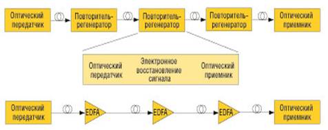
Fig. 3. Optical communication systems based on: a) a cascade of regeneration repeaters; b) a cascade of optical amplifiers EDFA
Although the optical signal generated by the original laser transmitter has a well-defined polarization, all other nodes along the path of the optical signal, including the optical receiver, should show a weak dependence of their parameters on the direction of polarization. In this sense, EDFA optical amplifiers, characterized by a weak polarization dependence of the gain, have a tangible advantage over semiconductor amplifiers. In fig. 3 shows the schemes of both methods.
In contrast to regenerators, optical amplifiers introduce additional noise, which must be taken into account. Therefore, along with the gain, one of the important parameters of the EDFA is the noise figure. EDFA technology is cheaper, for this reason it is more often used in actual practice.
Since EDFA, at least in price, looks more attractive, let's analyze the main characteristics of this system. This is the saturation power, which characterizes the output power of the amplifier (it can reach or even exceed 4 W); the gain, defined as the power ratio of the input and output signals; The power of the amplified spontaneous emission determines the level of noise that the amplifier itself creates. Here it is appropriate to give an example of a music center, where you can trace analogies in all these parameters. The third (noise level) is especially important, and it is desirable that it be as low as possible. Using the analogy, you can try to turn on the stereo without launching any disc, but at the same time turn the volume knob to the maximum. In most cases, you will hear some noise. This noise is created by amplification systems simply because they are powered. Similarly, in our case, spontaneous emission occurs, but since the amplifier is designed to emit waves in a certain range, the photons of this particular range will be more likely to be emitted into the line. This will create (in our case) light noise. This imposes a limit on the maximum line length and the number of optical amplifiers in it. The gain is usually chosen such as to restore the original signal level. In fig. 4 shows the comparative spectra of the output signal in the presence and absence of a signal at the input.
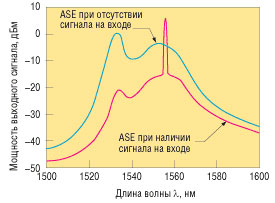
Fig. 4. EDFA output spectrum, taken with a spectral analyzer (ASE - noise spectral density)
Another parameter that is convenient to use when characterizing an amplifier is the noise factor — this is the ratio of the signal-to-noise parameters at the input and output of the amplifier. In an ideal amplifier, this parameter should be equal to one.
For EDFA amplifiers, there are three applications: preamplifiers, line amplifiers, and power amplifiers. The first are installed directly in front of the receiver. This is done to increase the signal-to-noise ratio, which makes it possible to use simpler receivers and can reduce the price of equipment. Line amplifiers are aimed at simply amplifying the signal in long lines or in the case of branching of such lines. Power amplifiers are used to amplify the output signal directly after the laser. This is due to the fact that the laser power is also limited and it is sometimes easier to just put up an optical amplifier than to install a more powerful laser. In fig. 5 schematically shows all three methods of applying EDFA.

Fig. 5. Application of different types of optical amplifiers.
In addition to the direct optical amplification described above, an amplifying device is currently being prepared for entry into the market, using the Raman amplification effect for this purpose and developed in Bell labs (Bell Labs). The essence of the effect lies in the fact that a laser beam of a certain wavelength is sent from the reception point towards the signal, which swings the crystal lattice of the waveguide in such a way that it begins to emit photons in a wide range of frequencies. Thus, the overall level of the useful signal rises, which allows to slightly increase the maximum distance. Today, this distance is 160-180 km, compared to 70-80 km without Raman amplification. These devices manufactured by Lucent Technologies will hit the market in early 2001.
What was discussed above is technology. Now a few words about the implementations that already exist and are actively used in practice. First, we note that the use of fiber optic networks is not only the Internet, and perhaps not so much the Internet. Fiber-optic networks can transmit voice and TV channels. Second, let's say that there are several different types of networks. We are interested in long-distance trunk networks, as well as localized networks, for example, inside one city (the so-called metro solutions). At the same time, for backbone communication channels, where the rule “the thicker the pipe, the better” works perfectly, the DWDM technology is the best and most reasonable solution. The situation is different in urban networks in which requests for traffic transfer are not as great as those of the main channels. Here, operators use the good old transport based on SDH / SONET, operating in the 1310 nm wavelength range. In this case, to solve the problem of insufficient bandwidth, which, by the way, is not very urgent for urban networks, you can use the new SWDM technology, which is a kind of compromise between SDH / SONET and DWDM (read more about SWDM technology on our CD-ROM ). In accordance with this technology, the same fiber-optic ring nodes support both single-channel data transmission at a wavelength of 1310 nm and spectral compaction in the 1550 nm range. Savings are achieved by “switching on” an additional wavelength, which requires adding a module to the appropriate device.
DWDM and traffic
One of the important points when using DWDM technology is transmitted traffic. The fact is that most equipment that currently exists supports only one type of traffic at a single wavelength. As a result, a situation often arises when traffic does not fully fill the fiber. Thus, a channel with a formal bandwidth equivalent to, for example, STM-16, transmits less “dense” traffic.
Currently, there is equipment that implements a full load of wavelengths. In this case, one wavelength can be “filled” with heterogeneous traffic, say, TDM, ATM, IP. An example of this is the equipment of the Chromatis family manufactured by Lucent Technologies, which can transmit all types of traffic supported by I / O interfaces at the same wavelength. This is achieved through the built-in TDM cross-switch and ATM switch. Moreover, the additional ATM switch is not pricing. In other words, additional functionality of the equipment is achieved at almost the same cost. This allows us to predict that the future is for universal devices capable of transmitting any traffic from
optimal use of bandwidth
DWDM tomorrow
Moving smoothly to the development trends of this technology, we certainly will not open America if we say that DWDM is the most promising optical data transmission technology. This can be attributed to a greater extent with the rapid growth of Internet traffic, whose growth rates are approaching thousands of percent. The main starting points in development will be an increase in the maximum transmission length without optical signal amplification and the realization of a larger number of channels (wavelengths) in one fiber. Today's systems provide transmission of 40 wavelengths, which corresponds to a 100-GHz frequency grid. Next in line for entering the market are devices with a 50 GHz grid supporting up to 80 channels, which corresponds to the transmission of terabit streams over a single fiber. And today you can hear the statements of the laboratories of development firms, such as Lucent Technologies or Nortel Networks, about the imminent creation of 25 GHz systems.
However, despite such a rapid development of engineering and research thought, market indicators make their own adjustments. The past year was marked by a serious fall in the optical market, as evidenced by a significant drop in the stock price of Nortel Networks (29% for one trading day) after it announced difficulties with marketing its products. Other manufacturers were in a similar situation.
At the same time, if in the western markets some saturation is observed, then the eastern ones are just beginning to unfold. The most striking example is the Chinese market, where a dozen national-scale operators race to build trunk networks. And if “they have”, the issues of building backbone networks have already been practically resolved, then in our country, sadly, there is simply no need for thick channels to transmit our own traffic. Nevertheless, the Departmental and Corporate Communication Networks exhibition held in early December revealed the great interest of domestic operators in new technologies, including DWDM. And if such monsters as “Transtelecom” or “Rostelecom” already have transport networks on the scale of the state, then the current energy sector is just beginning to build them. So, despite all the troubles, the future is behind optics. And DWDM will play a significant role here.
Literature
1. http: // www. ***** / production. php4? & rubric97
2. Journal ComputerPress №1 2001
Basic definitions
Optical fiber ?? it is a glass or plastic thread used to transfer light inside of itself through total internal reflection.

The structure of the fiber optic cable is very simple and similar to the structure of a coaxial electric cable, but instead of the central copper wire, it uses thin fiber (about 1-10 microns in diameter), and instead of internal insulation ?? glass or plastic shell that does not allow the light to go beyond the limits of fiberglass. We are dealing with the regime of the so-called total internal reflection of light from the boundary of two substances with different refractive indices (in a glass envelope, the refractive index is significantly lower than that of a central fiber). The metal braid of the cable is usually absent, since shielding from external electromagnetic interference is not required here, but sometimes it is still used for mechanical protection from the environment (such cable is sometimes called armored, it can combine several fiber-optic cables under one sheath).
Fiber optics ?? a section of applied science and engineering that describes such fibers. Optical fibers are used in fiber-optic communication, which allows digital information to be transmitted over long distances and at a higher data transfer rate than electronic communications. In some cases, they are also used to create sensors.
Fiber optic connection ?? communication built on the basis of fiber optic cables. The abbreviation VOLS (fiber-optic communication line) is also widely used. It is used in various spheres of human activity, ranging from computer systems and ending with structures for communication over long distances. It is today the most popular and effective method for the provision of telecommunications services.
Materials
Glass optical fibers are made of quartz glass, but other materials can be used for the far-infrared range, such as fluoropirconate, fluorine aluminate, and chalcogenide glasses. Like other glasses, these have a refractive index of about 1.5.
The use of plastic optical fibers (Plastic optical fibers) is currently developing.
The sources of light emission in fiber-optic cables are:
- lEDs or light emitting diodes (Light Emmited Diode, LED);
- semiconductor lasers, or laser diodes (Laser Diode).
For single-mode cables, only laser diodes are used, since with such a small diameter of the optical fiber, the luminous flux created by the LED cannot be directed into the fiber without large losses ?? does it have an overly wide radiation pattern, while the laser diode ?? narrow. Therefore, cheaper LED emitters are used only for multimode cables.
Story
Fiber optics, although a widely used and popular means of providing communications, the technology itself is simple and has been developed for a long time. An experiment with changing the direction of the light beam by way of refraction was demonstrated by Daniel Colladon and Jacques Babinet as early as 1840. A few years later, John Tyndall used this experiment in his public lectures in London, and in 1870 he published a work on the nature of light. Practical application of technology was found only in the twentieth century. In the 1920s, experimenters Clarence Hasnell and John Bird (John Berd) demonstrated by the experimenters the possibility of transmitting images through optical tubes. This principle was used by Heinrich Lamm for the medical examination of patients. Only in 1952, the Indian physicist Narinder Singh Kapany (Narinder Singh Kapany) conducted a series of his own experiments, which led to the invention of optical fiber. In fact, he created the very bundle of glass filaments, and the shell and core were made of fibers with different refractive indices. The shell actually served as a mirror, and the core was more transparent ?? so managed to solve the problem of rapid dispersion. If the beam had not reached the end of the optical filament before, and it was impossible to use such a transmission tool over long distances, now the problem has been solved. Narinder Kapani by 1956 improved the technology. A bunch of flexible glass rods transferred the image with almost no loss or distortion.
The invention of fiber optic by Corning specialists in 1970, which allowed, without repeaters, to duplicate a telephone signal data transmission system over a copper wire for the same distance, is considered to be a turning point in the history of the development of fiber optic technologies. The developers managed to create a conductor that can save at least one percent of the optical signal power at a distance of one kilometer. By today's standards, this is a fairly modest achievement, and then ?? necessary condition in order to develop a new kind of wired connection.
Initially, the fiber was multiphase, that is, it could transmit hundreds of light phases at once. Moreover, the increased diameter of the fiber core allowed the use of inexpensive optical transmitters and connectors. Much later, they began to use fiber of higher performance, over which only one phase could be transmitted in the optical medium. With the introduction of single-phase fiber signal integrity could be maintained at a greater distance, which contributed to the transfer of large amounts of information.
The most popular today is a single-phase fiber with zero offset wavelength. Since 1983, it occupies a leading position among the products of the fiber-optic industry, proving its performance over tens of millions of kilometers.
Classification
There are several classes of optical fibers for the features of the structure and principle of operation:
- Singlemode fiber
- Multimode Fiber
- Optical fibers with gradient refractive index
Optical fibers with a stepped profile of the distribution of refractive indices.
The profile of the refractive index of various types of optical fibers: multimode fiber with a step change in the refractive index (a); multimode fiber with a smooth change in the refractive index (6); single mode fiber (in).
![]()
All optical fibers are divided into two main groups: multimode MMF (multi mode fiber) and single mode SMF (single mode fiber).
The concept of "mod" describes the mode of propagation of light rays in the inner core of the cable. Is the single-mode cable using a central conductor of very small diameter, commensurate with the wavelength of light ?? from 5 to 10 microns. In this case, almost all the light rays propagate along the optical axis of the fiber, not being reflected from the external conductor. The fabrication of ultrathin quality fibers for single-mode cable is a complex technological process, which makes single-mode cable quite expensive. In addition, it is quite difficult to direct a beam of light into a fiber of such a small diameter, and a significant part of its energy is not lost. Multimode cables use wider inner cores that are easier to make technologically. The standards define the two most common multimode cables: 62.5 / 125 µm and 50/125 µm, where is 62.5 µm or 50 µm ?? diameter of the central conductor, and 125 microns ?? diameter of outer conductor.
Multimode fiber
Multimode fibers are divided into graded index multi mode fiber and step index multi mode fiber.
In a multimode cable, the trajectories of light rays have a noticeable variation, as a result of which the waveform at the receiving end of the cable is distorted. The central fiber has a diameter of 62.5 microns, and the diameter of the outer shell ?? 125 microns (this is sometimes referred to as 62.5 / 125). A conventional (non-laser) LED is used for transmission, which reduces the cost and increases the service life of transceivers compared to a single-mode cable. The wavelength of light in a multimode cable is 0.85 microns. The permissible cable length reaches 2-5 km. Currently multimode cable ?? The main type of fiber optic cable, as it is cheaper and more affordable.
Multimode fiber with a stepped profile
The first fibers for data transmission were multimode with a stepped refractive index profile. For the propagation of light due to the total internal reflection, it is necessary to have a core index of refractive index n1, slightly larger than the refractive index of the cladding glass n2. At the interface of two glass media, the following condition must be satisfied: n1\u003e n2. If the refractive index of the core of the optical fiber n1 is the same over the entire cross section, then it is said that the fiber has a stepped profile. Such a fiber is multimode. The pulse of light propagating in it consists of many components directed in separate modes of the fiber. Each of these modes is excited at the entrance of the fiber at its specific angle of entry into the light guide and is guided along the core along it, passing with different paths of the beam. Each mode passes a different distance of the optical path and therefore passes the entire length of the fiber for a different time. In this case, if we feed a short (rectangular) pulse of light at the fiber input, then at the output of the multimode fiber we will receive a “diffuse” time pulse. These distortions due to the dispersion of the delay time of individual modes are called mode dispersion.
Multimode fiber with gradient profile
In a multimode optical fiber with a stepped profile, the modes propagate along optical paths of different lengths and therefore arrive at the end of the fiber at different times. This dispersion can be significantly reduced if the refractive index of the glass core decreases parabolic from the maximum value n1 at the fiber axis to the value of the refractive index n2 on the surface of the interface with the shell. An optical waveguide with such a profile, (when the refractive index changes smoothly) is called a gradient optical fiber. Rays of light pass through such a fiber in wave or helical spirals. The further the beam of light deviates from the axis of the fiber, the stronger it is wrapped back to the axis. In this case, since the refractive index from the axis to the edge of the core decreases, the speed of light propagation in the medium increases. Due to this, the “longer” optical paths are compensated by a shorter transit time. As a result, the difference in the time delays of different rays disappears almost completely.
Single mode fiber
Single-mode fibers are subdivided into step single-mode fibers (step index single mode fiber) or standard SF fibers (standard fiber), DSF dispersion shifted fibers (dispersion-shifted single mode fiber), and NZDSF (non-zero shifted dispersion fibers) dispersion-shifted single mode fiber).
In a single-mode cable, almost all the rays travel the same way, as a result of which they all reach the receiver at the same time, and the waveform is almost not distorted. A single-mode cable has a center fiber diameter of about 1.3 microns and transmits light only with the same wavelength (1.3 microns). The dispersion and signal losses are very small, which makes it possible to transmit signals over a much greater distance than in the case of a multimode cable. For single-mode cable, laser transceivers are used that use light exclusively with the required wavelength. Such transceivers are still relatively expensive and not too durable. However, in the future, single-mode cable should be the main due to its excellent characteristics.
Stepped profile fibers
A mode dispersion in an optical fiber can be eliminated if the structural parameters of a stepped fiber are selected in such a way that only one mode will be guided in it, namely ?? fundamental (main) fashion. However, the main mode is also broadened in time as it passes through such a fiber. This phenomenon is called chromatic dispersion. It is a property of the material, therefore, as a rule, it occurs in any optical fiber, but in the wavelength range from 1200 to 1600 nm it is relatively small or absent. For the manufacture of a stepped fiber with a low attenuation, which only directs the fundamental mode in the wavelength range of more than 1200 nm, the diameter of the mode field should be reduced to 8-10 microns. Such a stepped fiber is called a standard single-mode optical fiber.
Multistage Fiber
The profile of the refractive index of a conventional single-mode fiber has a stepped profile. For such a profile structure, the sum of the dispersion of the material in the waveguide dispersion at a wavelength of about 1300 nm is zero. For modern data transmission devices over an optical fiber, using wavelengths of 1550 nm or simultaneous transmission of signals at several wavelengths, it is desirable to have zero dispersion at other wavelengths. And for this it is necessary to change the wave dispersion and, consequently, the structure of the refractive index of the fiber. This leads to multi-stage or segmental refractive index profiles. Using these profiles, it is possible to produce optical fibers in which the wavelength with zero dispersion is shifted to 1550 nm (fiber with shifted dispersion) or the dispersion values are very small in the entire wavelength range from 1300 nm to 1550 nm (fiber with smoothed or compensated dispersion).
The diameter of the core single-mode fibers 7-9 microns. Due to the small diameter, only one mode of electromagnetic radiation is transmitted through the fiber, thereby eliminating the effect of dispersion distortion. Currently, almost all manufactured fibers are single-mode.
Fiber Optic Elements
- Optical receiver
Optical receivers detect signals transmitted over a fiber-optic cable and convert it into electrical signals, which then amplify and then restore their shape, as well as sync signals. Depending on the transmission speed and system specifics of the device, the data stream can be converted from a serial view to a parallel one.
- Optical transmitter
An optical transmitter in a fiber-optic system converts the electrical sequence of the data supplied by the components of the system into an optical data stream.
- Preamp
An amplifier converts an asymmetric current from a photodiode sensor into an asymmetric voltage, which is amplified and converted into a differential signal.
- Chip synchronization and data recovery
This chip must recover the sync signals from the received data stream and their clocking. The phase-locked loop circuit required to recover the clock pulses is also fully integrated into the synchronization chip and does not require external clock sync pulses.
- Optical cableconsisting of optical fibers under a common protective sheath.
Fiber optic transceivers
In order to transmit data through optical channels, the signals must be converted from electrical to optical, transmitted over the communication line, and then converted back into electrical form in the receiver. These transformations occur in the transceiver device, which contains electronic components along with optical components.
A time-division multiplexer widely used in transmission technology allows you to increase the transmission speed up to 10 Gb / s. Modern high-speed fiber optic systems offer the following speed standards for transmissions.
|
SONET standard |
SDH standard |
Transmission speed |
|
51.84 MB / s |
||
|
155.52 MB / s |
||
|
622.08 MB / s |
||
|
2,4883 GB / s |
||
|
9.9533 Gb / s |
New methods of multiplex wavelength division or spectral compaction make it possible to increase the density of data transmission. To do this, multiple multiplex information streams are sent over a single fiber channel using the transmission of each stream at different wavelengths. The electronic components in the WDM receiver and transmitter are different compared to those used in a time division system.
Advantages of fiber optic communications
- Broadband optical signals due to extremely high carrier frequency. This means that information can be transmitted over a fiber-optic line with a speed of about 1 Tbit / s;
- Very low attenuation of the light signal in the fiber, which allows you to build fiber-optic communication lines with a length of up to 100 km or more without regeneration of signals;
- Resistance to electromagnetic interference from surrounding copper cable systems, electrical equipment (power lines, electromotive installations, etc.) and weather conditions;
- Protection against unauthorized access. Information transmitted via fiber-optic communication lines can hardly be intercepted by a non-destructive cable;
- Electrical safety. Being, in fact, a dielectric, optical fiber increases the explosion and fire safety of the network, which is especially important in chemical and oil refineries, while servicing high-risk technological processes;
- The durability of fiber optic ?? The service life of fiber-optic communication lines is at least 25 years.
Disadvantages of fiber optic communications
- The relatively high cost of the active elements of the line, which convert electrical signals into light and light into electrical signals;
- The relatively high cost of welding optical fiber. This requires precision, and therefore expensive, process equipment. As a result, when an optical cable is broken, the cost of fiber-optic fiber restoration is higher than when working with copper cables.
Application of fiber optic lines
Optical fiber is actively used to build urban, regional and federal communication networks, as well as for the construction of interconnecting lines between urban exchanges. This is due to the speed, reliability and high bandwidth of fiber networks. Also, through the use of fiber-optic channels, there are cable television, remote video surveillance, video conferencing and video broadcasting, telemetry and other information systems. In the future, it is proposed to use the conversion of speech signals into optical signals in optical fiber networks.
Federal State Budgetary Institution of Higher Professional Education
St. Petersburg National Research University
information technology, mechanics and optics
Faculty IKVO Department MIPiU
Direction (specialty)090900 "Information Security"Group 2750
Qualification (degree)bachelor
abstract
On the course "Concepts of modern science"
Fiber-optical communication.
Completed:
2nd year student
gr. 2750
Bogopolskaya E.A.
Received:
ph.D., Associate Professor of the Department
Komarova I.E.
G.S. Petersburg
1. Basic concepts ……………………………… 1
2.Materials ……………………………… .............. 2
3. History ……………………………………………… ... 2
4. Classification ……………………………………… ... 3
5. Elements of fiber-optic lines ………. 7
6. The benefits of fiber-optic communications ... ... 9
7. The disadvantages of fiber-optic communication type ... ... .... 9
8. Using fiber-optic lines ....... 9