With an increase in electricity consumption and the number of appliances in the house, there is a need to replace standard panels with so-called “plugs” with modern machines. The optimal solution to the situation is to delegate such work to professionals. But if you have the knowledge, skills and patience collected detailed recommendations They will help you install and assemble the shield yourself.
General questions about electrical panels
This device is required for installation in apartments and private houses. The shield performs several important functions for a comfortable and safe stay:
- input and distribution of electricity;
- creating suitable operating conditions for devices and wiring (voltage regulation).
Choosing an electrical panel is a fairly important stage, at which you can already make the first mistake. Some residents try to select components that will fit organically into the interior, and at the same time do not think about the properties of the materials.
One should not lose sight of the fact that the installation of an electrical panel can only be carried out if it is made of fire-resistant materials. It is also important to consider its capacity, since during operation it will be necessary to uniformly arrange the elements of the electricity input and distribution system.
Installation and installation of the switchboard
Before starting installation, it is necessary to draw up detailed diagram shield To do this, you need to determine the power supply system used in a particular room. Then you need to group the consumption points.
Most often used next diagram groupings:
- room sockets;
- switches and lighting;
- other electrical appliances.
It is important to know! For connection to the panel of boilers, washing and dishwashers use separate groups. It is also necessary to take into account that for each device they use different machines that differ in characteristics.
Table of examples on the use of machines in an electrical panel circuit.
We begin internal installation
Once the diagram is drawn up, the installation procedure can begin. It is recommended to take shields that are designed for large quantity connections (than is in the diagram). This will reduce costs during further modernization of the premises.
For reference! For work we will need the following tools: Phillips and straight screwdrivers, pliers, a tool for removing insulation from wires, a multimeter.
Modern technologies used in the manufacture of panels make it possible to secure the automatic devices and additional devices necessary for the distribution of electricity using DIN rails.
The use of such structures allows you to assemble the shield elements in just 4 steps:
- 1) Attach the machine to the rack with the rear groove.
- 2) Slightly pull out the fastening latch using a screwdriver.
- 3) Apply slight pressure on the body of the machine.
- 4) Release the latch to secure the element.
For successful installation of an electrical panel, it is important to consider what type of panel is used and how the site for its installation is prepared. For hidden wiring It would be more rational to install a built-in or hidden shield. For its installation to be successful, you need to prepare a niche in the wall (if one is not provided for by the layout of the room). After the housing is installed, you can begin connecting groups of electricity consumers, input cables and electricity meters.
Read more about the installation procedure
So, what should you do first before installing an apartment panel? Decide on the device, size and material.
To find out all the necessary parameters, you need to answer a number of questions:
- 1) The number and energy consumption of devices connected to the network through auxiliary machines.
- 2) Type of electrical wiring (hidden or open).
- 3) The presence or absence of a counter in the future dashboard.
- 4) Indoor environmental conditions (temperature, humidity).
- 5) Issues of ergonomics and design.
The answer to the first question can be found in the table. Keep in mind that every device with a consumption of more than 1.5 kW/h needs its own automatic machine.
There are 2 types of shields: closed and open. The choice depends on the wiring: more often, with a hidden type, a closed shield is chosen and vice versa. Having decided on the dimensions, we choose the material - most often it is welded iron or heat- and light-resistant plastic.
Let's move on to choosing a place to install the apartment panel. There are several rules to take into account here.
- 1) Location away from gas and water equipment.
- 2) Taking into account the thickness of the wall.
- 3) Convenience of subsequent operation.
- 4) Compliance with safety precautions during further operation.
With an open shield, the installation process is easier: we fasten the device to the surface with self-tapping screws with dowels or dowel-nails. With closed ones it is more difficult - we make a niche in the wall, coat it with a solution of alabaster or plaster and mount the “box” in the box. We connect the wires, strip the ends, and mark the phase.
In addition to the rail, distribution or “terminal blocks” (necessary for connecting neutral conductors) should be attached to the panel body. If the room is old and the system has only a phase (3 phases) and a working zero (blue wire), only one terminal block is needed.
After this, a fire extinguishing device is installed protective shutdown(RCD). Because it may burn due to short circuit, it must be protected using a circuit breaker of the required rating. The working zero, after leaving the RCD, should be connected to its own bus, and from there, wiring to consumers should be done.
Assembly instructions
The electrical panel includes an input circuit breaker, an electric meter (if necessary), an RCD, standard circuit breakers, neutral and grounding busbars. The DIN rail serves as the basis for installing the machines.
After installing the rail, assemble the shield in this order:
- input machine;
- universal machines;
- zero bar;
- grounding strip.
The input circuit breaker must be three-pole when three-phase current, two-pole with single-phase, similar to an RCD (residual current device) and an electric meter. Connections are secured using factory “combs” or homemade structures, made from copper wire.
Important to remember! The wiring must be made of the same material and connected uniformly.
For reference! Blue indicates common zero, red indicates phase, yellow-green indicates grounding.
When installing electric meter you should limit yourself to connecting wires to it, and then call a specialist who will make the final connection. After installation, be sure to pay attention to whether the smell of burnt wiring spreads throughout the room.
What else do you need to know?
Here are a few more requirements and tips for beginners and experienced electricians:
- 1) When installing an apartment panel, you should always remember safety precautions and perform work only on a de-energized network.
- 2) Do not skimp on units.
- 3) Entrust the calculations of the parameters of the RCD, input and other circuit breakers, the cross-section and material of the wires to professionals.
- 4) After six months of operation, the contacts must be broached.
- 5) Install a box with a child safety lock.
- 6) Remember the need to seal the meter.
- 7) Label the machines.
- 8) Maintain uniformity in connections, materials, markings and documentation.
Adequately assess your capabilities and do not hesitate to ask for help. The safety of living in a room directly depends on the proper functioning of the electrical wiring.
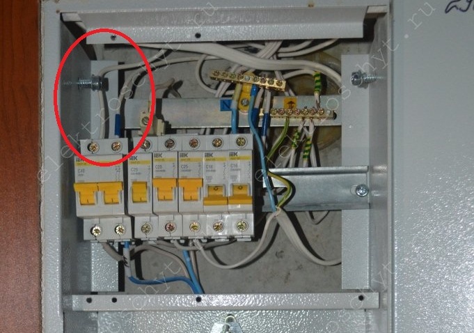
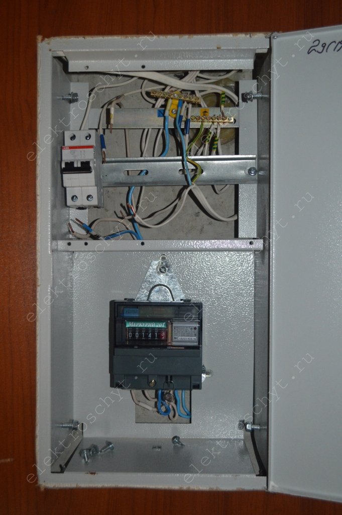
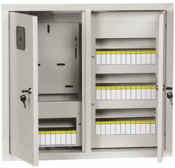
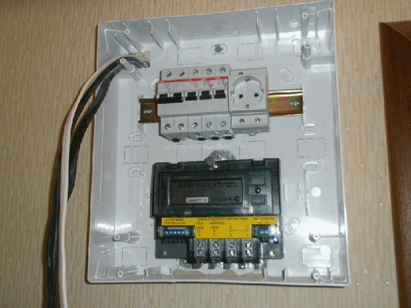
I replaced the CO-505 meter in the apartment panel with a Mercury 201 meter. Now it is necessary to replace the machines and install an RCD in the apartment panel, this must be done for several reasons. The photo below shows the apartment panel and the diagram of the panel from the developer at the time of delivery of the house.

Why is it necessary to change the automatic devices in the apartment panel and install an RCD? Because the apartment panel was assembled by the developer with gross violations, namely:
Firstly— the cross-section of the input wire of the PPV (commonly called “noodles”), which comes from the floor panel to the apartment panel, is 4 sq. mm. and on such a wire to protect it, it is installed introductory machine at 25A no more, and the developer installed a 40A input circuit breaker in the apartment panel, i.e. It turns out that in case of high load in the apartment, our input wire will melt, and the 40A circuit breaker will not turn off. Therefore, it is necessary to install a 25A input circuit breaker in the apartment panel to protect the PPV wire of 4 sq. mm;
Secondly— the outgoing circuit breakers in the apartment panel are set to 25A, which is also a gross violation. Because all household sockets are designed for a current of no more than 16A, and even then, if these sockets are from quality manufacturers, and if they are from Turkey or China, then there will not be 16A there. The lights and sockets in the apartment are connected with a 3x2.5 PPV wire; one wire from the 25A circuit breaker in the apartment panel goes to both the light and the sockets. We will install machines with rated current 16A, so that our sockets do not melt;

Thirdly— let’s throw out all the Chinese IEK machines, and install more reliable “home” ABB machines in the apartment panelSH 200 series;
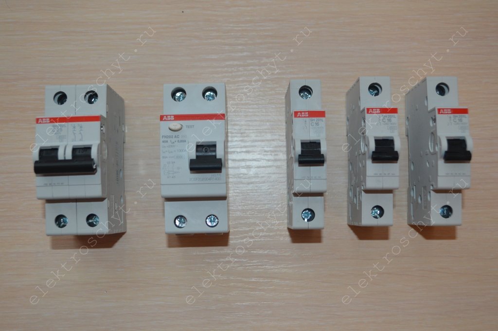
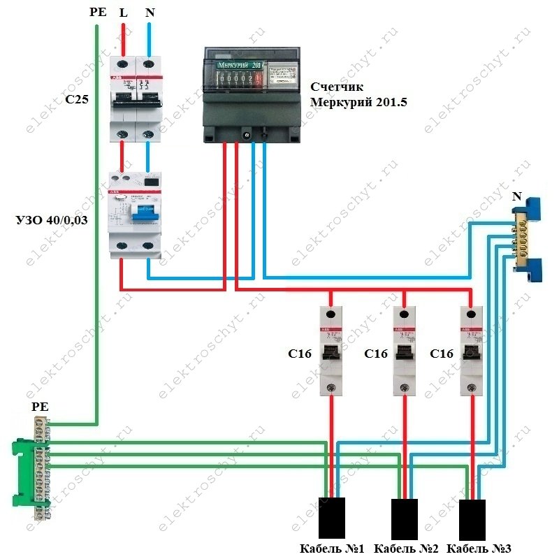
fourthly— we will install in the apartment panel an RCD from ABB “home” series FH 202 with a rated current of 40A, a step higher than the 25A input circuit breaker. RCDs from well-known ABB brands,Schneider Electric, Legrand does not exist at 32A. I note that we installed a 50A RCD with a leakage current of 30 mA in the floor panel, but again, this is Sassin from China, which you should not trust with your life. But we will not remove the Chinese RCD in the floor panel; we will leave it as additional differential protection.

Because If we add an RCD to the apartment panel, then the layout of the apartment panel will change relative to the original panel diagram from the developer.
Apartment shield. Scheme.
Let's start replacing the machines and RCDs in the apartment panel. First what needs to be done is turn off the input circuit breaker and RCD in the floor panel. Then we unscrew the metal panel (plastron) in the apartment panel and “mark” the wires with electrical tape, blue for the working zero N, yellow-green for protective PE, we don’t touch the phase wire, it remains white. You can apply markings with a regular pen or marker, but you need to be careful with the wires so as not to erase the inscriptions. Our wires are all white (the developer, as usually happens, saves on everything) and it is easy to confuse or forget where in the apartment panel we have a phase, where is zero, and where is the protective conductor.

After this, you can unscrew the wires from the machines. The zero working and protective conductors of the outgoing lines to the apartment can not be touched, because Our machines will be single-pole. The first thing we install in the apartment panel is on a DIN rail and connect the ABB 25A input circuit breaker. PPV wire 4 sq. mm. Ours is mono-core, so there is no need to crimp it with the NShVI ferrule.
Next, we install and connect into the apartment panel according to the diagram a 40A ABB RCD with a leakage current of 30 mA. We connect the RCD in the apartment panel with a PV-3 stranded wire, the ends of which are crimped with gray NShVI sleeve lugs for 4 sq. mm.
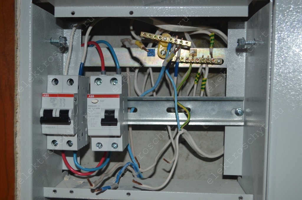
We install single-pole (single-module) ABB SH 201 16A circuit breakers on a DIN rail in the apartment panel.

We will connect the single-pole circuit breakers in the apartment panel with a comb, which we still have after dismantling the IEK circuit breakers.

Care should be taken to ensure that the comb fits, because... It happens that machines and combs from different machines do not fit together well.

The comb is not installed quite level, because... The photo was taken even before the machine contacts were tightened.
We connect the phase wires of the outgoing lines to single-pole circuit breakers in the apartment panel.

We check the tightness of the contacts of the machines and the RCD. We supply voltage to the apartment panel by turning on the RCD in the floor panel. We turn on the 25A input circuit breaker, check the operation of the RCD by pressing the “TEST” button, it should turn off. Next, we supply voltage to consumers in the apartment by turning on single-pole circuit breakers.
If everything works for us, the light is on, then we cover the machines and RCDs in the apartment panel with a metal panel and paste the designations of the machines and RCDs into the apartment panel.
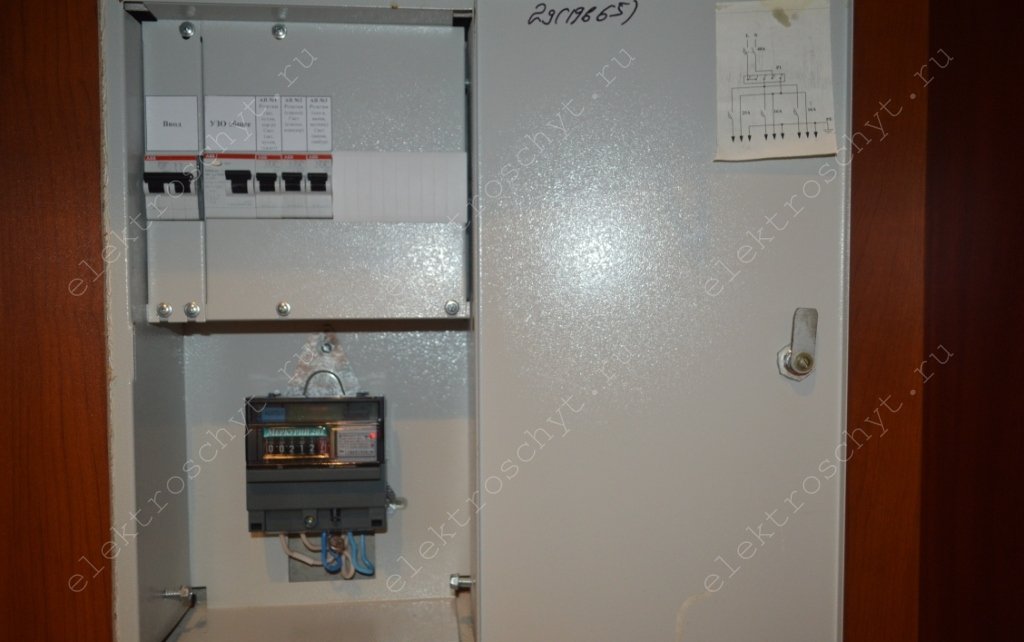
Well, that’s all, we installed and connected ABB automatic circuit breakers and RCDs to the apartment panel. I think that everyone needs to inspect the apartment and floor panels, and, if necessary, eliminate errors, because the electrical safety of your family, house or apartment depends on this, first of all.
Thank you for your attention.
The electrical panel is designed to distribute electricity and protect electrical wiring from overloads and short circuits. If previously a meter with a couple of automatic machines was enough to control the home electrical network, now everything has changed. More recently, 800 W of power was enough for the entire apartment. But now electricity consumption has reached 7 kW and even higher. The photo below shows the old (a) and modern (b) electrical wiring protection systems.
Old and new system protection of electrical wiring
As power consumption increases, today's network requires reliable protection devices. You can connect the electrical panel correctly by turning to specialists for help, or by assembling it yourself. In both cases, you need to understand its structure, electrical diagram, with installation requirements and rules, and also have the skills of an electrician.
In a wooden house, electrical installations should be done with special care and in compliance with fire safety rules.
Selecting an electrical panel
When choosing and installing an electrical panel, the following requirements apply to it:
- The box must accommodate the required amount of equipment, and even with a small margin. The size is determined by the number of elements typed. A single-pole circuit breaker consists of 1 module. The remaining devices are made with dimensions that are multiples of its size. The two-terminal network is made of two modules, and the size of the counter can be more than eight. If you calculate the required number of devices, you can select the desired box. Models are sold by size or number of modules that can fit inside, such as a 12- or 36-module device.
- The electrical panel is made of non-flammable material with an electrical safety sign indicating the rated voltage. The material is metal with a non-conductive coating or thermoplastic. The devices can withstand significant mechanical loads, and by design you can always find what you need.
- External and internal wires in the shield are marked with tags, where groups of elements should be indicated.
- The neutral and ground wires are connected to the blocks - one for each terminal. Tires are marked in blue for zero and black for phase.
- The choice of machines is made according to the cable cross-section. If a 2.5 mm 2 copper conductor is installed, the maximum permissible current for it will be 25 A. The parameters of the RCD or automatic circuit breaker are selected from the standard range in a decreasing direction, which is 16 A. It is advisable to connect the devices to each other with a busbar.
- The metal box must be grounded through the doors and body.
- Each box is sold with a passport, which indicates the type and class of the electrical panel, level of protection, precautions, installation method and other data.
- External wiring is inserted into the box in metal pipes or sleeves. Under the electrical panel of the internal installation, grooves for cable bundles are hollowed out to it (Fig. below).
Installation of an electrical panel with hidden wiring
Shield design
The type of product depends on how the box is designed. The device may be as follows:
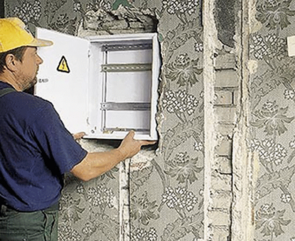
- built-in – for hidden electrical wiring(pic. below);
- overhead – in rooms with open wiring;
- floor-standing – mainly for industry.
The first type of box is inserted into a furnished niche and looks more attractive. Only the cover is visible on the wall and there are no protruding parts.

Built-in electrical panel
The inconvenience is the need to make a niche if it is not provided for in the design of the house. It is advisable to make a false wall from plasterboard. The box is attached through the back wall with the edges secured with glue or plaster.
It is prohibited to drill niches in load-bearing walls for electrical boxes!
The overhead model is universal. Open and hidden wiring can be connected to it.
The box for the equipment is made in the form of a box with a door (Fig. below). Inside it there are DIN rulers for installing a counter, machines and other equipment.
Overhead electrical panel
The metal box contains holes for wires at the top and bottom. Break-out hatches are made in a plastic case. The entry of wires into the box is protected using couplings and seals.
Electrical circuit and its creation
Electrical diagrams are necessary to install panels and circuits with your own hands, and they are also required by electricians when checking work. They can be drawn by hand or created using special programs. It is important that the circuit is made correctly and ensures convenient operation of the home electrical network.
First, the type of network to be connected is determined. In apartments it is single-phase, but in private houses it can be similar or three-phase.
The type of grounding system can be TNC, TN-S or TN-C-S. The first of them, combining grounding and neutral, was created according to old standards and is not used in new houses.
The schematic diagram of a typical electrical panel is shown in Fig. below. It shows symbols only.

Electrical diagram of the panel
A single-pole circuit breaker with a counter is installed at the single-phase input. Behind them there is a general fire protection RCD. At the next stage, all consumers are divided into groups. Where necessary, differential automatic machines are installed. If they are not needed, circuit breakers will suffice. The optimal distribution by room is as follows:
- groups of sockets;
- lighting with switches;
- separate automatic machines for the bathroom and powerful electrical appliances: washing machine, water heater, air conditioner, electric stove.
The technical characteristics of the machines are selected for each group.
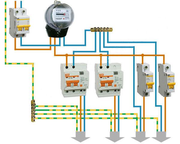
The simplest diagram of an electrical panel with a branching into 3 lines is shown in Fig. below.
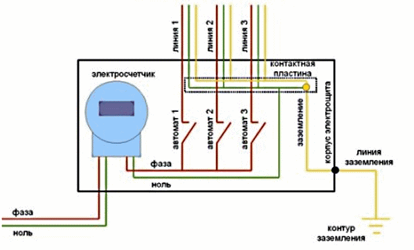
Electrical panel diagram with three electrical lines
Power is supplied to the meter (phase - red, zero - green), then goes to machines 1-3 and to the loads. The yellow color indicates the ground wire. It protects not only electrical appliances, but also the shield.
When connecting the meter, it is important not to confuse the phase and neutral terminals. All necessary explanations are in the instructions for it.
Shield elements
In the store you can buy a box right away with standard equipment, but often you need to select the elements yourself, according to the developed scheme. The types of elements and their purposes are as follows:
- DIN rails for placing equipment are metal plates that are attached to the electrical panel.
- Automatic input switch is an automatic switch for supplying electricity to a facility in the event of a circuit overload or short circuit (short circuit).
- Electricity consumption meter, installed in a separate box or together with other equipment. The type of meter can be induction or electronic. The connection diagrams for both are the same.
- Automatic switches that protect electrical wiring (selected according to the size and nature of the loads). They are selected with a focus on the highest current permissible for a certain wire cross-section when the load is on. The devices themselves can be protected from destruction by built-in fuses. The machine can operate instantly during a short circuit or after 15-60 minutes if the load current slightly exceeds the rated one.
- Distribution busbars for zero and grounding (can be open or closed).
- RCDs are devices for protecting people from electric shock. In addition, they prevent fire if a leakage current occurs in the wire. Instead, it is possible to use differential circuit breakers that additionally perform the function of a circuit breaker. In this case, instead of two devices, one is installed in the panel. This saves space. The nominal value of the device is chosen to be the same or one step higher than that of the machine in front of it.
- Sometimes a voltage relay is installed in the panels. This is not necessary, but if you have expensive electronics in your home, it is useful. If the voltage deviates from the set values, the circuit is broken. In addition, the device shows how the voltage in the circuit changes over time.
- Electrical wiring is a means of making connections.
The electrical wiring in the apartment is divided into groups and the load is calculated for each of them, after which the required sections of the cores are calculated, and the appropriate machine is selected. The layout is done approximately like this:
- groups of lighting and sockets in the hallway and bathroom (6 A, automatic);
- bedroom and hall lighting groups (6 A, automatic switch);
- lighting with sockets in the kitchen (16 A, automatic);
- groups of sockets in the living room and bedroom (16 A, automatic);
- separate connection to the electric stove, washing machine, air conditioner (depending on the power of consumers, an automatic switch is used).
For a group of sockets on the security system and home router, a 6 A circuit breaker is installed (you can add an uninterruptible power supply).
As a result, the total power when all loads are turned on simultaneously will be about 7 kW. For the internal network, a 32 A two-pole input circuit breaker should be installed here.
Installation and laying of wires is carried out with the following color markings:
- L – phase wire of white, red or brown color;
- N – zero blue wire;
- PE – yellow-green grounding.
Assembly Rules
- The color coding of the cores must be observed.
- Connections and installation of devices are carried out so that the inside of the panels are arranged clearly and clearly without a diagram (Fig. below). The more order they have, the easier it is to maintain.
- Power connections are made from top to bottom (more powerful devices are installed higher). With this placement, the electrical panel can be de-energized faster in the event of an accident.
- Power is supplied to the input last, when a final check of all connections has been made. Individual lines are tested for operability using temporary switching circuits.

Correctly assembled electrical panel
Installation work
An accessible location is selected for the shield. It is usually installed in the hallway, close to the power cable input. The installation height is 1.5-1.7 m. The meter is placed in a special shield box with an inspection window. Holes are made in the wall to secure the box with dowels or screws.
When the shield is installed on the wall, it can be assembled as follows:
- All groups of apartment wires are brought in advance to the panel where installation will be carried out. They should be marked to make it easier to assemble the circuit.
- DIN rails are attached to the shield with self-tapping screws for installing devices.
- A busbar is installed in the upper part for the neutral, and in the lower part for grounding.
- An input machine is installed on top.
- An introductory machine can be placed in a separate box, as for the counter.
- Groups of machines are placed from top to bottom, as power decreases. A special busbar is used as jumpers between them or they are made of copper wire with a cross-section of 4 mm. It is more convenient when the arrangement of devices in the panel and on the electrical circuit is the same.
- Cables and wires are inserted through holes into the box. The outer braid is cut off from them and the connection points are laid according to color. There should always be a reserve for further repairs. Connect the neutral wires to the top bus. Power is supplied to the upper terminals of the machines, and loads are connected to the lower terminals (phase connection to electrical groups). The cross-section of the wires is reduced, starting from the input and to areas with loads. The cross-section of the ground wire should not be less than that of the phase wire at the input. Twisting and the formation of coils should not be allowed. The power and neutral wires are routed on opposite sides of the panel.
- If the new meter is not connected, power to power tools and lighting can be supplied from the old one. The wires are brought out close to the meter so that the controller can later make the connection and seal the device.
- After connecting each group, it is advisable to check its functionality by applying voltage through a temporary connection circuit.
First, you should assemble the switchboard without switching, marking the installation locations of the devices (test assembly in the figure below). In this case, it should be possible to quickly turn off the power from inside and outside.
Trial assembly of the shield without switching
When the shield is closed, it must be possible to quickly check the presence of voltage using an indicator screwdriver or light bulb.
Floor shield
The floor panel (SHB) is located on the floor and belongs to several apartments. Usually it is locked and can only be opened with the help of the housing office electrician on duty. Residents are prohibited from accessing electrical equipment in the switchboard. They can only turn on the machines after operation by opening a special cover.
In Fig. Below is a schematic diagram of a floor board with wiring for three apartments.

Floor electrical panel diagram
All entrance switchboards are powered from a common riser (buses of phases L 1 L 2 L 3 and N in the figure above). In older housing stock, a TN-C type grounding system is used. Each phase is connected to a separate apartment, and the neutral wire bus is common. The power after the meter goes to the RCD, and then there is a branching on the line in the apartment (lighting, sockets and electric stoves). There should also be a packet switch in front of the meter, but it is not indicated on this diagram.
Modernization of the power supply can be done if you obtain permission from the housing office, and then buy the necessary devices that correspond to the required power and protective functions . The electrician will then make the following changes:
- The power supply is being replaced aluminum cable on copper of a suitable cross-section. The connection is made with a special terminal for dissimilar conductors.
- Instead of old circuit breakers new ones with the necessary characteristics are connected.
- Old grounding and neutral wires are being replaced with modern ones.
A radical way to replace electrical equipment in the distribution board will be done by installing a separate box in the apartment and moving the meter to it. A batch switch or switch with fuse links should be installed in the interfloor panel. This requires permission from the housing office.
Due to the fact that new devices are constantly appearing, you need to leave room for them in the dashboard. Among them are, for example, the following:
- power consumption limiter;
- power consumption meter (not a meter);
- phase balancing control device.
Installation. Video
You can learn about the installation features of the electrical panel by watching this video.
There is nothing difficult in choosing and assembling electrical panels for machines, meters and other equipment. It is important to correctly select, calculate the parameters and install electrical equipment in them, connecting it with wires. The diagram should be clear and easy to maintain.
An electrical panel is a device, often located near the entrance to a room, that serves to distribute electricity; it directs current to outlets and various appliances and devices.
An electricity meter is most often installed in the panel; it takes into account and calculates all energy costs. Most panel models provide for the connection of both residual current devices (RCDs) and automatic circuit breakers. They protect against network overvoltage and the risk of short circuits and are connected to the circuit immediately after the electricity meter.
Often you have to deal with the problem of connecting or replacing the machine in the panel. To do this work yourself, you will need a number of tools and, of course, compliance with safety precautions. Before, for example, using a separate new machine, you must turn off the power using the general switch. If there is none, then working under voltage is prohibited!
There are many connection diagrams and a whole carload of subtleties, so if you are not sure what you are doing, then it is better to entrust this work to a professional. Now we will look at connecting the machine in the panel for protection single-phase network. It is this network that is most often used in apartments and country houses, this is a so-called two-wire circuit, in which one wire is a phase, the other is a neutral.
Having removed the cover from the device, you can see a lot of wires and several already installed machines (unless, of course, you are installing the machine in a completely new panel), which are usually signed by conscientious electricians. Often the inscriptions are located directly on the panel, and therefore it is advisable to immediately designate the new machine that you are going to install. The easiest way to install a new machine to an existing one is to repeat the connection diagram that you will see. Moreover, it is advisable to save .
You need to remove the top insulation from the cable and strip each core about a centimeter. It is advisable to do this after you have decided on the required length of each core for free connection to the terminals. If the terminal blocks of the “grounding” and “neutral” wires have not yet been installed, then this needs to be done. The latter are usually blue.
Next, we connect the grounding and neutral conductors to the corresponding terminal blocks. Those. Now you need to attach a grounding conductor to one of the clamps; a similar procedure must be done for the “zero” conductor of the cable. Only now can we move on to the main issue - connecting the machine.
A mounting DIN rail is installed (if it is not already installed), onto which the switches will “snap.” You can move on to this right away, or you can first install a relay - an inexpensive option for the home that copes well with power surges. Then supply power to the first machine from the input or from the relay, if available. It should be connected to the rest from above using cable jumpers, but with a distribution bus the work will be faster and easier. Next, the wires are connected to the machines. It should look the same as in the picture.

On a note: best option- a ten-Amp machine, sometimes sixteen, but it does not provide adequate protection, although it is installed in most homes. By following these recommendations, it is possible correct connection circuit breaker.