DC and AC millivoltmeter and ohmmeter with linear scale
A schematic diagram of a millivoltmeter of DC and AC currents and an ohmmeter with a linear scale is shown in Fig. 49. The main element of the millivoltmeter is an ac amplifier. It consists of a source follower on a T17 field effect transistor, an emitter follower on a T18 transistor, and a three-stage amplifier assembled in a common-emitter circuit on a T18-T20 transistor. The output of the amplifier includes a rectifier and a dial indicator.
The electrical circuit of the mean voltmeter using a vacuum tube diode is shown in the figure. Linear voltage and current. The characteristics of the linear plate are necessary to ensure that the current is directly proportional to the voltage. The figure shows the diagram of the average reading of a variable voltmeter using a semiconductor diode.
The diode conducts during the positive half-cycle and does not conduct during half the cycle, as shown in the figure. The average current through the counter will be determined by the expression. It should be noted that this device can be used to indicate a constant voltage, but in this case the instrument reading must be multiplied by 2 x 11, i.e. when the diode carries on all the time. The figure shows a diagram of the average reading of a variable voltmeter using semiconductor diodes in the form of a full-wave rectifier.
To protect the pointer indicator from possible overloads that occur when the measurement limit is incorrectly selected, a silicon diode D25 is connected in parallel with it. To ensure the stability of the gain, the amplifier is covered by deep negative feedback. The same feedback allows to significantly improve the linearity of the dial indicator scale, especially at its beginning.
The main advantages associated with these voltmeters are that they are simple in design, have high input impedance, low power consumption and a uniform scale. The main disadvantage of these voltmeters is that they operate in the audio frequency range. Another disadvantage of such a voltmeter is that, because of the nonlinear voltage-current characteristic for a lower voltage, the voltmeter reading at a lower voltage is incorrect.
The drawings show electrical circuits for a peak voltmeter using a vacuum tube and a semiconductor diode. But this tension is again created during the next wave peak, as shown in the figure. A high value of the input resistance also gives a more linear relationship between the peak applied voltage and the instrument display.
The measured voltage applied to the input of the millivoltmeter is fed through the contacts of the relay P1 - the DC / AC converter and the resistor R93, which determines the input resistance of the millivoltmeter, to the push-button switch of the measurement limits and further to the input of the source follower. The upper limits of the measured voltages are set using the trimmer resistors R86, R88, R90, R92 and R95. The initial gain of the AC amplifier for measuring the alternating voltages is set using a trimmer resistor R104 included in the negative feedback circuit.
Also, the performance of the diode with inputs consisting of pulses and modulated waves improves. The DC amplifier connected to the diode rectifier must be equipped with stabilizing means to prevent drift in the output meter reading. Usually, a power supply with a regulated voltage is used in combination with a compensation circuit.
The main disadvantage of this system is the measurement of low voltage. If the applied voltage is too low, that is, the flow of some current during the entire voltage cycle because of the high electron emission rate, and the input resistance can be several hundred ohms, and it defeats the purpose with which electronic instruments are used. As mentioned earlier, most of the movements in meters are sensitive devices. This makes a voltmeter with a full scale rating of only 50 millivolts!
When measuring alternating voltage, the pushbutton switch B4 must be in the unlocked position. To measure constant voltages or resistance resistors, the button is pressed. In this case, an alternating voltage of 27 V from the winding of the power transformer is applied to the winding of the relay-converter through the diode D20. At the same time, another trimmer R106 is connected to the negative feedback circuit, by means of which the amplification factor of the AC amplifier is increased. This is due to the fact that the effective value of the pulsating voltage at the output of the converter differs from the effective value of the sinusoidal voltage.
To build voltmeters with practical scales from such sensitive movements, we need to find a way to reduce the measured amount of voltage to a level that can handle motion. For example, let's determine the required multiplier value so that this 1 mA, 500 Ω is moved exactly on a full scale with the applied voltage of 10 volts.
Knowing that the motion will be in full-scale mode with 1 mA current passing through it, and that we want it to happen at the applied voltage of 10 volts, we can fill the table as such. There are several ways to determine the value of the multiplier resistance. One way is to determine the impedance of the circuit using Ohm's law in the "total" column, and then subtract 500 ohms of movement to get the value for the multiplier.
The principle of measuring resistance is based on measuring the drop in the DC voltage on the corresponding resistor. For this purpose, the device includes a current stabilizer on the transistor T21. Depending on the measuring range, the operating current 1 is set using the push-button switch B2 (see Figure 47); 0.1 mA or 10 μA. At the same time, a working current of 1 mA is used on the limits of 0-30, 0-300 and 0-3000 ohms, 0.1 mA at the 0-30 kΩ limit, and 10 μA at the 0-300 kΩ limit. Accordingly, at the first limit, the maximum voltage drop is 30 mV, the second - 0.3 V and the rest - 3 V. To measure the resistance, you need to set the required limit, press the switch button B4 with a latch, connect the measured resistor to the input terminals and press the B5 , then the input of millivoltmeter Гн5 will be connected to the measured resistor.
Another way to determine the same resistance value would be to determine the voltage drop on the motion at the full scale of the deviation, and then subtract this voltage drop from the total amount to reach the voltage across the resistor of the multiplier. Finally, Ohm's law could be used again to determine the resistance for the multiplier.
In either case, you will get the same answer, and one method can be used as a check for another to check the accuracy of the work. At a voltage equal to 10 volts between the measuring wires of the meter, the current through the counter current will be exactly 1 mA, which is limited by the resistance of the "multiplier" and its own internal resistance to movement. After re-marking the reading scale from 0 to 10 V, anyone who scans the scale will interpret its reading as ten volts.
The voltage drop across the measured resistor is converted into a pulsating voltage by means of a DC to AC converter and measured by an AC millivoltmeter. In connection with the fact that a constant current of strictly fixed value flows through the measured resistor, the voltage drop across it is directly proportional to its resistance. Therefore, the ohmmeter scale is linear and you can use the scale of the dial microammeter.
Please note that the meter user does not need to know that the movement itself actually measures only a part of this ten volts from an external source. All that matters to the user is that the circuit as a whole functions to accurately display the total applied voltage.
This is how practical electric counters are designed and used: the sensitive motion of the counter is designed to work with the minimum voltage and current as much as possible for maximum sensitivity, then it is "deceived" by some divider built from precision resistors, indicating full scale, A much greater voltage or current is superimposed on the circuit as a whole. We have considered the design of a simple voltmeter here. Ammeters follow the same general rule, except that parallel "shunt" resistors are used to create a current divider circuit, in contrast to the series-connected voltage dividers "multiplier" used for voltmeters.
The power supply unit (Figure 48) includes a half-wave rectifier assembled on a diode D17. The voltage is stabilized by a parametric stabilizer on diodes D18, D19. A transistor T16 is provided on the transistor T16, which makes it possible to exclude the effect of the circuit on the parameters of the stabilizer.
Transistors of wide application, such as MP402-MP403, MP422-MP423, GT308-GT309, etc., can be used instead of the recommended transistors of the MP416 type. Instead of the transistor KTZ15 - transistors of types KT301, KT312, with current transmission coefficients B not less than 50. Instead of a field effect transistor KP103, you can use KP102 type transistors with any letter, changing the polarity of the supply voltage. All transistors, with the exception of the transistor type KT315, on which the current stabilizer is assembled, can have current transfer coefficients B of not less than 20.
Typically, it is useful to have several ranges installed for an electromechanical meter such as this, allowing it to read a wide range of voltages with a single movement mechanism. This is achieved by using a multi-pole switch and several multiplier resistors, each of which is designed for a certain voltage range.
The five-position switch comes into contact with only one resistor at a time. In the lower position, it contacts without a resistor, ensuring the setting is "off". Each resistor is sized to provide a specific full scale range for the voltmeter, based on a specific counter motion rating. The end result is a voltmeter with four different full-scale measurement ranges. Of course, in order to make this work reasonable, the scale of motion of the meter should be equipped with labels corresponding to each range.
As push-button switches it is most convenient to use a switch of type P2-K with a step of 10 mm or in extreme cases with a step of 15 mm. All variable resistors are of the SP-0,5 type, and the trimmer resistors are of the SPZ-46 type. Electrolytic capacitors, such as K50-6 for 15 and 25 V. The remaining capacitors are of the type K10-7B and MBM. All the permanent resistors are of the MLT type.
With this counter design, each value of the resistor is determined by the same technique using a known common voltage, total motion deviation and drag. Note the values of the resistor multiplier used for these ranges, and how odd they are. It is highly unlikely that a 5 kΩ precision resistor will ever be detected in a trash can, so voltmeters often choose the version of the above design that uses more general resistor values.
With each successively higher voltage range, more multiplier resistors are driven by a selector switch, making their series resistances by adding for the required total. Thanks to this meter design, this is exactly what we get.
The power transformer is assembled on the iron Ш-26, the core set is 50 mm. The primary winding, designed for 220 V, contains 1000 turns of PEV-1 wire with a diameter of 0.27 mm, a secondary 26 turns of PEV-1 wire with a diameter of 0.64 mm.
As an arrow micro-ammeter, a device of the M4206 type with a total deflection current of 300 μA and a frame resistance of 240 Ω is used, the scale of the instrument has 30 divisions. Instead, it is possible to use microammeters of any type with a current of a total deviation of 50-500 μA and a frame resistance of not more than 2000 Ω.
Schema and working explanations
The advantage, of course, is that the individual values of the multiplier resistors are more common than some odd values in the first design. However, from the point of view of the user of the counter there will be no noticeable difference in the function. The figure above shows the complete digital diagram of the voltmeter. You can turn on or off the backlight contacts.
In the diagram, you can see that we used an 8-bit link, but it's not mandatory, we can use a 4-bit link, but with a 4-bit communication program it gets a bit complicated. To filter out noise, the capacitors are placed through each resistor in the divider circuit, as shown in the circuit diagram above. Therefore, for each increment of 5 mV at the input, we will have an increase in the digital output.
If you use a microammeter with a scale having a different number of divisions, you can either re-create a scale with 30 divisions, or change the limits of measuring the voltages and resistances of resistors by changing the values of the resistors in the input divider. For example, using a microammeter with 50 scale divisions, it is expedient to make the following measurement limits: 0-0,05; 0-0.5; 0-5; 0-50 and 0-500 V, and the ohmmeter is 0-50; 0-500 Ohm, 0-5, 0-50 and 0-500 kΩ.
Therefore, for better accuracy of the digital output, we need to select a lower frequency. All the listed four functions are set by two registers. This bit can be disabled in the program when we need to stop the conversion. The work of this digital voltmeter project is explained step by step in the code below.
Due to the very high impedance, you can perform low-frequency measurements on different equipment without changing its performance. The full scale is rated for 1 volt, but the sensitivity depends on your device, the more digits, the better is the sensitivity of reading. Resistors that make up the input partition must have high accuracy and thermal stability, that is, a metal layer with a tolerance of 0.5%.
To adjust the millivoltmeter, disconnect the left-in-circuit capacitor C57 (see Figure 49) from the input attenuator and from the sound generator supply a voltage of 7.5 mV at a frequency of 1-5 kHz. The trimmer resistor R106 achieves the deviation of the instrument needle from the last scale division. After restoring the circuit, a voltage of 30 mV is applied to the input of the millivoltmeter from the sound generator, the measurement limit is 0-30 mV and the arrow is adjusted to the last division of the scale using the trimmer resistor R95. Then, the output voltage of the sound generator is increased and, by switching the subbands of the input attenuator, the upper limits of the AC voltage measurement subbands are set using the adjusted resistors R92, R90, R88 and R86.
Be careful to clean the components of the components so that the pond can perfectly adhere. It's unpleasant, but it's not easy to track resistors with low impedance, but if you have an old analog or digital tester that does not work, you can get it from there, otherwise you will patiently choose it with an ohmmeter, parallel or a series of resistors on sale, or you will use potentiometric trim tabs to calibrate now using the ohmmeter of the tester in accordance with the values shown in the diagram.
To calibrate the instrument in the DC voltage measurement mode, a voltage corresponding to the upper limit of a particular subband is applied to its input, and using the trimmer resistor R104, set the instrument needle to the last scale division.
Adjustment of the ohmmeter is reduced to the selection of the necessary values of the stabilizer current. To do this, parallel to the input jacks (Гн5, Гн6) of the device connect the reference milliammeter of direct current with the measurement limits 1; 0.1; 0.01 mA, set the mode of measuring the resistance or DC voltage and press the button Kn1 ("measurement"). Using one of the trimmer resistors R115, R117, R118, the currents of the stabilizer 1 are set in accordance with the selected sub-band; 0.1 and 0.01 mA.
Be careful to clean the components of the components so that the pond can perfectly adhere. It's unpleasant, but it's not easy to track resistors with low impedance, but if you have an old analog or digital tester that does not work, you can get it from there, otherwise you will patiently choose it with an ohmmeter, parallel or a series of resistors on sale, or you will use potentiometric trim tabs to calibrate now using the ohmmeter of the tester in accordance with the values shown in the diagram.
If there is no reference DC milliammeter, the ohmmeter can be calibrated as follows. Resistors with resistances equal to the upper limit of the ohmmeter (3, 30 and 300 kOhm) are taken with a tolerance of not worse than 0.5-1%, and, sequentially connecting them to the input of the instrument, set the corresponding measurement limits. Then push the button Kn1 and with the help of the trimmer resistors mentioned above, the deviation of the arrow of the device to the last division of the scale is achieved.
Millivoltmeter can be made as a separate stand-alone device or incorporated into the sound generator. To do this, you need to make a separate power supply with a voltage of about 15-24 V. If you apply a more sensitive microammeter, for example, with a current of a total deviation of 50-150 μA and instead of the specified Zener diode D21 - such as KC133 or KS139, then the voltage of the power supply can be reduced to 9 AT.
11. ELECTRONIC VOLTMETERS
In electronic voltmeters, the measured voltage is converted by analog electronic devices into direct current, which is fed to a magnetoelectric measurable mechanism with a scale graduated in voltage units. Electronic voltmeters have high sensitivity and a wide range of measured voltages (from tens of nanowires at a constant current of up to tens of kilovolts) to a large The input resistance (more than 1 MΩ) can operate in a wide frequency range (from a direct current to frequencies of the order of hundreds of m Jaggerz). These advantages have led to the widespread use of electronic voltmeters.
The most frequently used in electronic voltmeters are schemes with direct signal conversion (see § 4-5). In this case, analog electronic nodes can introduce significant errors. This is especially true when measuring low voltages or high-frequency voltages. Therefore, electronic voltmeters usually have relatively low accuracy classes (1-6). Voltmeters with balancing conversion generally have higher accuracy classes (0.2-2.5), but they are more complex and less convenient to operate.
Currently, many different types of voltmeters are produced. By their purpose and principle of operation, the most common voltmeters can be divided into voltmeters of direct current, alternating current, universal, pulsed and selective.
DC voltmeters. A simplified block diagram of such voltmeters is shown in Fig. 6-1, where VD - input
Figure 6-1 - Structural diagram of the electronic voltmeter of direct current
voltage divider; DCT - direct current amplifier; IM - magnetoelectric measuring mechanism. Angle of deviation of the indicator of the measuring mechanism, where k cb , k upt - coefficients of transformation (amplification), respectively VDand UPT,S U - voltage sensitivity of the measuring mechanism; k v is the conversion factor of the electronic voltmeter; U x - the measured voltage.
The serial connection of the voltage divider and the amplifier is a characteristic feature of the construction of all electronic voltmeters. This structure allows you to make voltmeters highly sensitive and multidimensional due to a change in a wide range of their total conversion factor . However, increasing the sensitivity of DC voltmeters by increasing the gain UPTruns into technical difficulties due to instability of work UPT,characterized by a change in k UTT and drift "zero" (spontaneous change in the output signal) of the amplifier. Therefore, in such voltmeters, as a rule, k UPT ≈ 1, and the main purpose UPT- provide a large input impedance of the voltmeter. In this regard, the upper limit of the measurement of such voltmeters does not fall below tens or millivolts.
To reduce the impact of instability UPTin voltmeters provide the possibility of adjustment before measuring the "zero" and the conversion factor of the amplifier.
The described structural diagram of a DC voltmeter is used in the composition of universal voltmeters (see below), since with a slight complication - adding an AC voltage converter to a constant voltage, it becomes possible to measure the AC voltage.
To create high-sensitivity DC voltmeters (microvoltmeters), direct current amplifiers are used, constructed according to the M-DM (modulator-demodulator) scheme shown in Fig. 6-2, a, where M- modulator; DM-demodulator; Г-generator; Have ~ - the amplifier of an alternating current. Amplifiers of AC do not pass a constant component of the signal, and therefore they do not have a drift of "zero", characteristic for UPT.In Fig. 6-2, ba simplified time diagram of the voltages at the output of individual blocks is shown. The generator controls the operation of the modulator and demodulator, which in the simplest case are analog switches synchronously closing and breaking them with a certain frequency. On the output of the modulator generates a unipolar pulse signal whose amplitude is proportional to the measured voltage. The variable component of this signal is amplified by the amplifier V ~, and then it is rectified by a demodulator. The use of a controlled demodulator makes the voltmeter sensitive to the polarity of the input signal.
The average value of the voltage of the output signal is proportional to the input voltage U CP = kU X . Since such an amplifier circuit allows to practically eliminate the drift of "zero" and has a stable gain, the coefficient k can reach large values, for example, k = 3.33 · 10 5 for a microvoltmeter B2-25. As a result, for microvoltmeters, the upper limit of measurements with the highest sensitivity can be one microvolt. Thus, the direct current microvoltmeter В2-25 has the upper measurement limits of 3, 10-300, 1000 μV at the main reduced error ± (0,5-6).%.
AC voltmeters. Such voltmeters consist of an AC to DC converter, amplifiers of a magnetoelectric measuring mechanism. Two generalized structural diagrams of AC voltmeters are possible (Fig. 6-3), differing in their characteristics. In the voltmeters according to the scheme in Fig. 6-3, ameasured voltage and x first converted to a constant voltage, which is then fed to the UPTand THEM,which are, in essence, a DC voltmeter. Converter Etcis a low-inertia non-linear link (see below), therefore voltmeters with such a structure can operate in a wide frequency range.
Fig. 6-2. Structural diagram (a) and time diagram of signals (b) of a dc electronic voltmeter with an amplifier M - DM
Fig. 6-3. Structural diagrams of AC voltmeters
zone (from tens of hertz to 10 "MHz). To reduce the effect of distributed capacitances and inductances of the input cable and the input circuit of the device, the converters are usually performed in the form of remote probe nodes. At the same time, these shortcomings UPTand the features of the work of nonlinear elements at low voltages do not allow making such voltmeters highly sensitive. Usually their upper limit of measurements at maximum sensitivity is tens - millivolts.
In voltmeters made in accordance with the scheme 6-3, b, thanks to the preliminary amplification, it is possible to increase the sensitivity. However, the creation of AC amplifiers with a large gain factor operating over a wide frequency range is a rather difficult technical task. Therefore, such voltmeters have a relatively low frequency range (1 - 10 MHz); The upper limit of measurements at maximum sensitivity is tens or hundreds of microvolts.
Depending on the type of AC-to-DC converter, the voltmeters can be proportional to the peak (peak), average (average rectified) or the actual values of the measured voltage. In this connection, voltmeters are called, respectively, the amplitude, mean or effective voltmeters. However, regardless of the type of transducer, the AC voltmeter scale, as a rule, is graded at the actual sinusoidal voltage values.
Voltmeters of amplitude valuehave amplitude-value converters (peak detectors) with an open (Figure 6-4, a)or closed (Figure 6-5, a)inputs, where u BX and u OUT - input and output voltage of the converter. If the volt-

Fig. 6-4. Scheme ( a) and time diagrams of signals (band at)an amplitude value converter (peak detector) with an open input
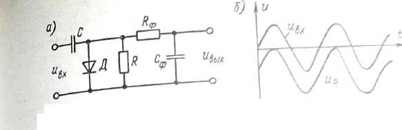
Fig. 6-5. Diagram (a) and timing diagrams of signals (b) of the amplitude value converter with closed input
meter has the structure of Fig. 6-3, a, then for the converter u in x = u x. In amplitude converters with an open input, the capacitor is charged almost to the maximum and x max
positive (for a given diode inclusion) of the value of the input voltage (see Figure 6-4, b).The ripple of the voltage u OUT on the capacitor is explained by its recharging with the diode open, when u BX\u003e u OUT, and by discharging it through the resistor R
with the diode closed, when u BX< u ВЫХ.
Как видно из рисунка, отпирание диода
и подзаряд
конденсатора происходит лишь в короткие
промежутки времени θ, определяемые
постоянными времени заряда т 3
и разряда т р.
Для того чтобы пульсации напряжения на
выходе преобразователя
были незначительными, необходимо
обеспечить т 3
< l/f В,
т р > l / f H, where f B ,
f H
- upper and lower limits of the frequency range of the voltmeter. The average value of the output voltage u cp
≈
u xmax
and, consequently, the angle of deflection of the indicator of the measuring mechanism 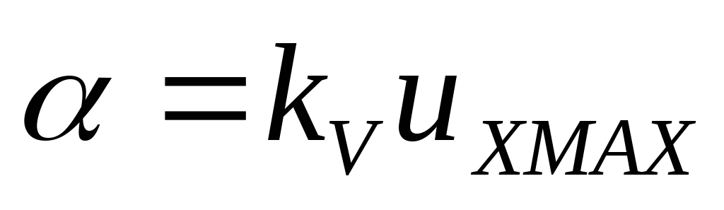 , where k v coefficient of conversion of the voltmeter.
A feature of the amplitude converters with an open input is that they pass a constant component of the input signal (positive for a given diode inclusion). Thus, for u BX = U 0 + U m sin ωt with U 0\u003e U m (see Figure 6-4, c), the average value of the output voltage u cp ≈ Uo+ U m . Therefore, α= k v (U 0 + U m ). Obviously, for u BX<0 подвижная часть THEMwill not deviate, since in this case the diode D is closed.
In converters with a closed input (Figures 6-5, a, b) in steady state on a resistor R regardless of the presence of a constant component of the input signal, there is a pulsating
voltage u R varying from 0 to - 2 U m , where U m - amplitude of the variable component of the input voltage. The average of this voltage is practically equal to U m . To reduce the ripple of the output voltage in such converters, a low-pass filter is set R Φ C Φ . Thus, the voltmeter readings in this case are determined only by the amplitude value of the variable component of the input voltage u X that is, a= k V U m .
Features of amplitude converters with open and closed inputs should be taken into account when measuring by electronic voltmeters.
Since the scale of voltmeters is graded at the actual values of the sinusoidal voltage, when measuring the voltages of the other form, it is necessary to do the corresponding recalculation if the amplitude of the measured voltage is known. Amplitude value of measured voltage of non-sinusoidal shape U m = k a . c U ETC = 1,41 U ETC , where k a . c = 1.41 is the amplitude of the sine curve; U ETC - voltage value, measured on the scale of the device. The actual value of the measured voltage , where k a is the amplitude of the measured voltage.
Average voltmetershave converters of alternating voltage to a constant, similar to converters used in rectifiers (see § 5-4). Such voltmeters usually have the structure shown in Fig. 6-3, b. In this case, the pre-amplified voltage is applied to the rectifier converter and x which increases the sensitivity of the voltmeters and reduces the influence of nonlinearity of the diodes. The angle of deviation of the moving part of the measuring mechanism in such voltmeters is proportional to the average rectified value of the measured voltage,
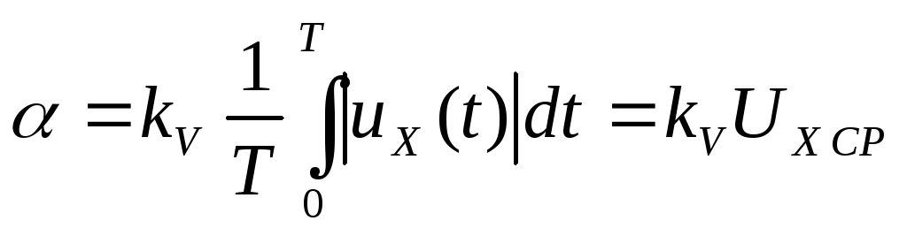 .
.
The scale of such voltmeters is also graded at the actual values of the sinusoidal voltage. When measuring the voltage of a nonsinusoidal form, the average value of this voltage, and the actual value, where U PR is the voltmeter reading; k FS = 1.11 - the shape factor of the sinusoid; to f – coefficient of the shape of the measured voltage. .
Current-Rating Voltmetershave an AC voltage converter with a quadratic static conversion characteristic 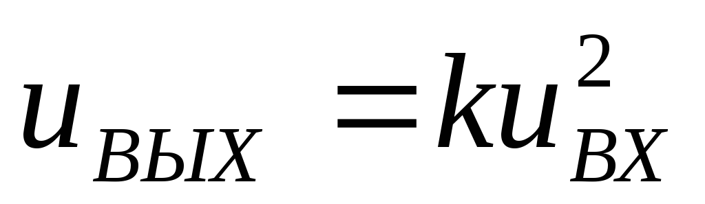 . As such a converter, thermal converters, quadrature devices with piecewise linear approximation of a parabola, electron tubes and others are used. In this case, if the voltmeter of the effective value is made according to the structural diagrams shown in
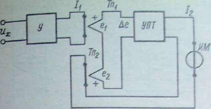
Fig. 6-6 Scheme of the electronic voltmeter of the effective value (with a uniform scale)
fig. 6-3, then regardless of the shape of the measured voltage curve, the deviation of the indicator of the measuring mechanism is proportional to the square of the effective value of the measured voltage:
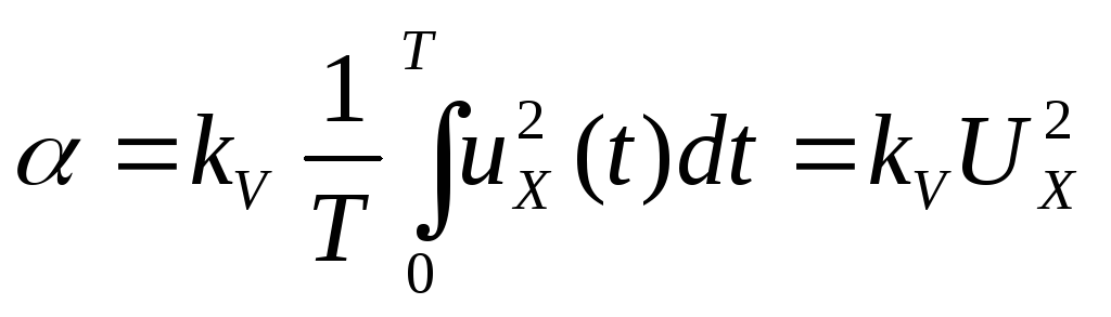 .
.
Apparently, such a voltmeter has a quadratic scale. The voltmeter of the effective value with a uniform scale is shown in Fig. 6-6, where two quadrature converters are used, one of which is included in the negative feedback circuit. As such converters, thermal converters are used, for which the thermo-emf is equal, respectively: 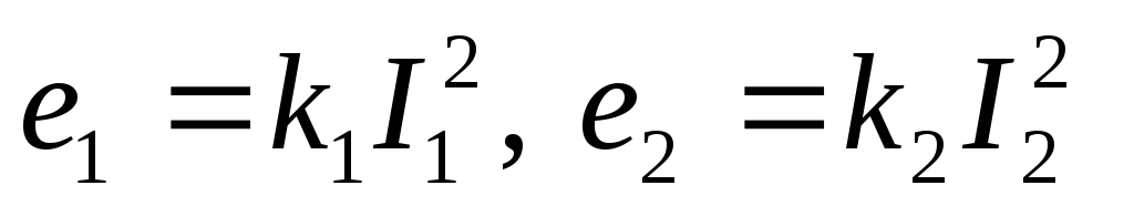 ,
where I 1, I 2
- currents flowing through the heaters of thermocouples; k 1
,
k 2
- coefficients that depend on the properties of thermal converters. The output current of a broadband AC amplifier is proportional to the measured voltage: I 1 = k U U X ,
so
,
where I 1, I 2
- currents flowing through the heaters of thermocouples; k 1
,
k 2
- coefficients that depend on the properties of thermal converters. The output current of a broadband AC amplifier is proportional to the measured voltage: I 1 = k U U X ,
so  .
With a large gain UPTits input signal
.
With a large gain UPTits input signal  . Consequently,
 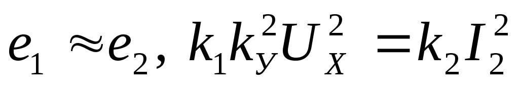 and the deviation of the indicator of the measuring mechanism
Thus, the deviation of the indicator of the measuring mechanism is proportional to the effective value of the measured voltage.
As an example, we can mention the millivoltmeter AC VZ-43 with an amplitude converter, which has an upper measuring range of 10, 30 mV - 3 V and a basic error of ± (4-25) % in the frequency range 10 Hz-1 GHz; millivoltmeter of alternating current VZ-41 with rectifier converter, having upper pre-

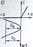
Fig. 6-7. Scheme (a) and timing diagram of signals (b)a diode-compensating voltmeter
3, 10 mV - 300 V and the basic error ± (2.5-10)% in the frequency range of 20 Hz - 10 MHz; VZ-40 alternating current microvoltron with thermal converters in direct and reverse conversion circuits having upper limits of 30, 100 μV - 300 V and basic error ± (2,5-10)% in the frequency range 5 Hz - 5 MHz.
In addition to the AC voltmeters under consideration, they are currently being manufactured diode-compensating voltsmeters.
The operating principle of such voltmeters is explained by the circuit in Fig. 6-7, a, the main elements of which are: Diode D; High-sensitivity magnetoelectric galvanometer - zero-indicator NO;standard voltage divider ONE.Based on the idealized representation of the current-voltage characteristic of a diode (Figures 6-7, b)in the form of a broken line, we can assume that in the absence of voltage applied to the input voltmeter and x the current does not flow through the diode. When the voltage is connected, u = U m sin ω t at U to < U m a certain current starts flowing through the diode, causing a deviation of the zero-indicator indicator. Increasing (in modulus) the compensation voltage U K, achieve a lack of current through NO.At the moment when the current in NOdisappears, U m = U K . Count off the position of the handle ONE.High sensitivity NOand high accuracy of installation U K allow to obtain small measurement errors (up to 0.2%). These voltmeters are the most accurate of existing electronic voltmeters, have high input impedance, wide frequency range (up to 10 3 MHz). The lack of the device is the complexity of operation.
Diode-compensating voltmeters can be used to accurately measure the sinusoidal voltage, as well as for calibration and calibration of electronic voltmeters. Among the various types are voltmeters designed for measurement of both periodic and impulse voltages. Thus, the device is a compensating voltmeter B3-49 having upper measurement limits of 300 mV, 1-1000 V and a basic error of ± (0.15-2.7)% at a constant current and ± (0.2-12)% on an alternating current in frequency range of 20 Hz - 1 GHz.
Along with voltmeters, the instrument-making industry produces measuring converters of voltage (AC and DC) and current (AC and DC) into a unified DC signal. The principles of constructing such transducers are in many respects similar to the considered principles of constructing electronic voltmeters. A distinctive feature of the converters is the absence of a measuring mechanism at the output.
Universal voltmeters. Such voltmeters are designed for measuring DC and AC voltages. A generalized structural diagram is shown in Fig. 6-8, where ATswitch. Depending on the position of the switch ATthe voltmeter operates according to the scheme of an AC voltmeter with a converter P(position 1) or a DC voltmeter (position 2).
In universal voltmeters, also called combined, it is often possible to measure resistance R x . In such voltmeters there is a converter П R, the output voltage of which depends on the unknown resistance: U out = f (R x ) (see §6-5). Based on this relationship, the scale of the device is graduated in units of resistance. When measuring a resistor with an unknown resistance is connected to the input terminals of the converter, and the switch is put in position 3.
As an example, we indicate a universal voltmeter B7-26 having upper limits of measurements at a constant current of 0.3, 1-300 V, alternating current 1, 3-300 V, a basic error of ± 2.5% at a constant current and ± (4 -6)% on alternating current in the frequency range of 20 Hz-10 3 MHz. In addition, this device is designed to measure the resistance to direct current in the range 10 Ω - 1000 MΩ with a basic error not exceeding ± 2.5%.
Impulse voltmeters. To measure the amplitude of the pulses of signals of different shapes
impulse voltmeters are used. Features of the work of im-
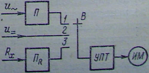
Fig. 6-8. Structural diagram of a universal voltmeter.
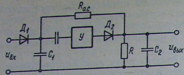
Fig. 6-9. Compensation circuit of the amplitude converter
pulsed voltmeters are determined by the short duration τ of the measured pulses (from 10-100 ns) and the significant duty ratio θ = T / τ (up to 10 9), where T- pulse repetition period.
Pulse voltmeters are calibrated in the amplitude values of the measured pulses.
Impulse voltmeters can be performed according to the structural scheme of Fig. 6-3, a, while using amplitude-value converters with an open input, the output voltage of which should be equal to the amplitude U m measured pulses. The high duty cycle of the pulses and their short duration impose stringent requirements on the amplitude value converters. Therefore, in modern impulse voltmeters compensatory schemes of amplitude converters are used (Fig. 6-9). The input pulses u BX charge the capacitor C 1. The variable component of the voltage on this capacitor, caused by its measured impulses and discharge between pulses (similarly to Figures 6-4, c), is amplified by the AC amplifier and rectified by diode D 2. Time constant of the chain RC 2 is chosen sufficiently large, so the voltage across the capacitor FROM 2 in the interval between the pulses varies insignificantly. From the output of the converter using a resistor R 0 . c feedback to the capacitor C 1 is applied to the compensating voltage. With a large amplification factor of the amplifier, this leads to a significant decrease in the variable component of the voltage across the capacitor FROM 1 so that in the steady state the voltage on this capacitor is practically equal to the amplitude of the measured pulses, and the output voltage is proportional to this amplitude:.
In the normative technical documentation for pulsed voltmeters, the range of permissible pulse widths (or their frequency) and duty cycle are indicated, under which the voltmeter errors are within the limits of normalized values. Thus, the voltmeter B4-9A has upper measuring limits of 2.5, 10, 20 V and the basic error ± (2,5-
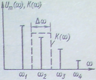
Fig. 6-10. The spectrum U m (ω) of a signal and the amplitude-frequency characteristic of an ideal voice filter.
4.0)% at a repetition rate of 1 Hz - 300 MHz and a duty cycle from 2 to 3 · 10 8.
Selective voltmeters. Such voltmeters are designed to change the actual value of the voltage in a certain frequency band or the actual value of the individual harmonic components of the measured signal.
The principle of the selective voltmeter is to separate individual harmonic components of the signal or signal of a narrow frequency band by means of a tunable bandpass filter and to measure the effective value of the extracted signals. In Fig. 6-10, the continuous vertical lines show the spectrum of some measured signal, and the dashed line represents the idealized amplitude-frequency characteristic of a bandpass filter having a transmission coefficient K (ω) = k = const for  , K (ω) - for the remaining frequencies, where ω PF is the average tuning frequency of the bandpass filter, and Δω is the bandwidth of the filter. The frequency ω PF can be varied within the limits determined by the device of the selective voltmeter. For the measured signal with the spectrum shown in Fig. 6-10, a sinusoidal signal with frequency ω 2 and amplitude kU m (ω 2) appears at the output of the bandpass filter. Therefore, by measuring the effective value of the output signal of the bandpass filter, it is possible to determine the effective value of the harmonic component of the measured signal at a frequency ω 2. By varying the frequency ω PF, it is possible to measure the effective values of various harmonic components.
A physically realizable bandpass filter does not have a strictly rectangular amplitude-frequency response. This can lead to the fact that through this filter pass the neighboring harmonic components with a certain coefficient  . In addition, the spectrum of the measured signal can be such that several harmonic components of this signal pass through the bandpass filter within the passband Δω. In these cases, the selective voltmeter measures the effective value of the sum of the harmonic components passed through the filter, taking into account the actual transmission factors for each component.
A simplified block diagram of a selective voltmeter is shown in Fig. 6-11. Measured signal u X through electoral

Fig. 6-11. Block diagram of a selective voltmeter
input amplifier VUfed to the mixer Cm,designed to convert the frequency spectrum of the measured signal. At the output of the mixer, a signal appears proportional to the measured signal, but with the frequencies of the spectrum  ,
where f Xi is the frequency of the harmonic components of the input signal; f F is the frequency of the signal of the sinusoidal generator F, also called the heterodyne. Intermediate frequency amplifier UPCHtuned to some fixed average frequency f IFCH .
Therefore, the output UPCHonly the component of the output signal of the mixer whose frequency
,
where f Xi is the frequency of the harmonic components of the input signal; f F is the frequency of the signal of the sinusoidal generator F, also called the heterodyne. Intermediate frequency amplifier UPCHtuned to some fixed average frequency f IFCH .
Therefore, the output UPCHonly the component of the output signal of the mixer whose frequency  . This signal corresponds to the harmonic component of the measured signal with frequency
  .
The effective value of this harmonic component is measured by a voltmeter of the effective value VDZ.By changing the oscillator frequency f D ,
it is possible to measure the effective value of various harmonic components of the signal and x .
.
The effective value of this harmonic component is measured by a voltmeter of the effective value VDZ.By changing the oscillator frequency f D ,
it is possible to measure the effective value of various harmonic components of the signal and x .
The function of the bandpass filter in this circuit is performed by UPCH.Due to a fixed (non-tunable) tuning frequency value UPCHthis amplifier has a large gain and a narrow bandwidth, which ensures high sensitivity and selectivity of the selective voltmeter.