Attention novelty! The voltage regulator for the entire house SKAT ST-12345 is designed specifically for networks with unstable mains voltage. Stabilizes the voltage in the range from 125 to 290 Volts! Has a high power of 12 kVA! Warranty - 5 years! Test video of the stabilizer see.
High and high tension. Causes
As in ours in our electric networks there can appear a high or increased voltage. As a rule, to increase the voltage can lead to poor-quality electrical networks or accidents in networks. The disadvantages of networks include: obsolete networks, low-quality network maintenance, a high percentage of depreciation of electrical equipment, ineffective planning of transmission lines and distribution stations, not controlled by the growth in the number of consumers. This leads to the fact that hundreds of thousands of consumers receive high or increased voltage. The voltage in such networks can reach 260, 280, 300 and even 380 Volts.
One of the reasons for the increased, as it is not strange, may be the reduced voltage of consumers located far from the transformer substation. In this case, often electricians intentionally increase the output voltage of the electrical substation, in order to achieve satisfactory current indicators for the latter in the transmission line of consumers. As a result, the first in the line voltage will be increased. For the same reason, you can observe an increased voltage in the holiday villages. Here the change in current parameters is related to the seasonality and periodicity of current consumption. In summer, we observe an increase in electricity consumption. In this season there are a lot of people in dachas, they use a lot of energy, and in winter the current consumption drops sharply. On weekends, consumption in suburban areas increases, and on working days falls. As a result, we have a picture of uneven energy consumption. In this case, if you set the output voltage to the substation (and they are usually not of sufficient power) normal (220 volts), then in summer and in the weekend the voltage will suddenly drop and be reduced. Therefore, electricians initially adjust the transformer for increased voltage. As a result, in winter and during working days, the tension in the villages is high or high.
The second large group of reasons for the occurrence of high voltage is the misalignment of the phases when consumers are connected. It often happens that the connection of consumers happens chaotically, without a preliminary plan and project. Or during the implementation of the project or the development of settlements there is a change in the value of consumption at different phases of the transmission line. This can lead to the fact that in one phase the voltage will be lowered, and on the other phase increased.
The third group of causes of increased voltage in the network are accidents on power lines and internal lines. Here we should distinguish two main reasons - the break of zero and the entry of high-voltage current into ordinary networks. The second case is a rarity, it happens in cities in a strong wind, a hurricane. It happens that the power line of electric transport (tram or trolleybus) falls when it breaks down on the line of city networks. In this case, 300 and 400 volts can enter the network.
Now consider what happens when the "zero" disappears in the internal house networks. This case happens quite often. If two phases are used in one entrance of the house, then if there is a zero (for example, there is no contact at zero), the voltage value changes at different phases. In the phase where the load in the apartments is now less, the voltage will be too high, in the second phase it is too low. And the voltage is distributed inversely proportional to the load. So if in one phase the load is at this moment 10 times greater than the other, then we can get 30 volts (low voltage) in the first phase, and 300 volts (high voltage) in the second phase. Which will lead to the combustion of electrical appliances, and possibly a fire.
What is dangerous high and high voltage
High voltage is dangerous for electrical appliances. A significant increase in voltage can lead to the combustion of devices, their overheating, additional wear. Especially critical to high voltage electronic equipment and electromechanical devices.

Elevated stress can lead to a fire in the house, causing great damage.
If it is a question of reducing the voltage in the network, finding the problem is more difficult, because it depends on the type of electricity consumer used. There are two main types of consumers: resistance and engine.
As for the consumer of the resistance type, for them the voltage drop is directly proportional to the drop in the current consumed (Mr. Oma l = U / R). For fuses, a weak current carries no danger. If we take the resistance consuming 300 watts (figure 55.2) at 240 V, then at 24 V it will consume only 3 watts.
As for the type of engine, it is first necessary to distinguish them by the action of a greater moment of resistance (Figure 55.3). So, we can compare the reciprocating (greater resistance moment? And drive motors (less resistance time?).
![]()
Regarding centrifugal fans, they are between these two categories. Mostly their characteristics do not withstand a significant drop in the supply voltage, in connection with which they are classified as devices with a large moment of resistance.
Recall that the ability of the engine to drive the device (torque on the shaft) depends on the square of the supply voltage. That is, if it is designed to operate on 220 V power, and the voltage drops to 110 V, then the torque will decrease by 4 times (Figure 55.4). If the torque is too high when the voltage drops, the motor will stop. At the same time, the current consumed by the motor will be equal to the starting current that it will consume during the forced stop. At this point, only the built-in protection (thermal relay) can save it from severe overheating, which will quickly turn off the power.
![]()
If the resistance of the driven device is low, reducing the voltage will reduce the speed of rotation, since the motor has a smaller available power. This property is widely used in most multi-speed motors that rotate fans of air conditioners (Figure 55.5). When switching to the BS (high speed), the resistance is short-circuited and the motor is powered from 220 V. Its rotation speed is nominal.

When switching to the MS (low speed), the resistance is connected in series with the motor winding, which causes the voltage on it to decrease. Accordingly, the torque on the shaft also decreases, thus, the fan starts to rotate at a reduced speed. The current consumption becomes smaller. This property is widely used in the manufacture of electronic speed controllers (based on thyristors), used to control the condensing pressure, changing the speed of rotation of fans in air-cooled capacitors (Figure 55.6).
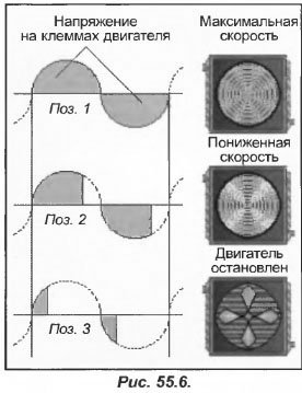
These regulators, called converters or current gauges, function like other regulators-limiters, working on the principle of "cutting off" the frequency of the amplitude of an alternating current.
In the first position, the pressure is high and the speed controller completely passes the half-periods of the network. At the motor terminals, the voltage (shaded area) corresponds to the power supply in the network, and it starts to rotate at the maximum speed, while consuming the rated current.
In the second position, the condensation pressure begins to decrease. It enters the regulator, cutting off part of each half-cycle that enters the engine input. The voltage at the motor terminals decreases, along with the speed and current consumption.
In the third position, the voltage is too weak. Since the engine torque is less than the fan resistance moment, it stops and starts to heat up. Thus, the speed controllers are basically tuned to the maximum permissible minimum speed.
In addition, the "shearing" method can be used in single-phase motors, when they are used for drives with a low torque of resistance. With regard to three-phase motors (used to drive machines with high resistance), it is recommended the use of multi-speed motors, DC motors or frequency converters.
In everyday life we often have to face a drop in tension. It can be caused by a momentary shutdown or a sudden drop in current. In order to limit the voltage drop, it is necessary to correctly select the cross section of the supply wires. But in some cases, the decrease in the voltage level is not due to a decrease in supply in the supply wires.
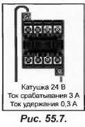
For example, take the coil of an electromagnet 24 V, which controls a small contactor (Figure 55.7). When the electromagnet is triggered, it consumes a current equal to 3 A, and when it is held, it is 0.3 A (10 times less). In other words, the connected electromagnet consumes a current equal to ten times the current of the hold mode. Despite the fact that the switching-on time is short (20 ms), this factor can have an effect in large command circuits with a large number of contactors and relays.
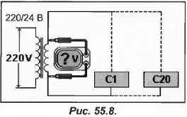
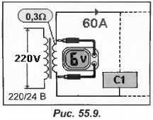
In the presented scheme (Fig. 55.8) 20 contactors - С1-С20 are installed. As soon as the current is turned off, they are all in standby mode, and when turned on, they are triggered. When activated, each contactor consumes 3 A, which means that the secondary winding of the transformer will go current 3 × 20 = 60 A. If the resistance of the secondary winding is 0.3 ohms, then the voltage drop on it with the contactors will be 0.3 × 60 = 18 V. Since the voltage of the contactors reaches only 6 V, they can not work (Figure 55.9).
In this case, the transformer together with the wiring will be overheated, and the contactors themselves will be buzzing. And this will continue until the automatic circuit breaker operates or the fuse blows.
If the resistance of the secondary winding of the transformer is 0.2 Ohm, then when the contactors are switched on, the voltage in it will be 0.2 × 60 = 12 V. The contactors will be powered from 12 V instead of 24 V, and there is no chance that they will turn on. Their work will be similar to kA in the previous example, since the voltage in the network is abnormally high.
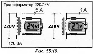
The difficulties with the resistance on the secondary winding are explained by the significant idling voltage at the output of the transformer, in contrast to the voltage under load. With increasing current consumption, the output voltage decreases.
As an example, consider a transformer 220/24 (Figure 55.10) with a capacity of 120 VA, connected to the 220 V network. If the transformer outputs a current of 5 A, the output voltage will be 24 V (24 × 5 = 120 VA). But if the current consumption is reduced to 1 A, the output voltage becomes large, for example, 27 V. This is caused by the resistance of the secondary wire.
As soon as the current starts to decrease, the output voltage rises. And the reverse situation: as soon as the current consumed becomes more than 5 A, the output voltage decreases to 24 V, as a result of which the transformer overheats.
If the transformer is of low power, then there can be some difficulties, so do not neglect the power selection of the transformer.
If you are tired of constantly changing burnt out lamps, use one of these tips. But in all cases, success is achieved through a significant reduction in voltage.
In the daytime and especially at night, the voltage in the network often reaches 230-240V, which leads to accelerated burning of the filaments of the electric bulbs. It is estimated that an increase in voltage by only 4% compared to the nominal voltage (that is, from 220 to 228V) reduces the lifetime of electric bulbs by 40%, and with an increased "power supply" of 6%, this time is reduced by more than half.
At the same time, reducing the voltage on the lamps by only 8% (up to 200-202V) increases the "experience" of their work by 3.5 times, at 195V it increases almost 5-fold. Of course, with a decrease in voltage, the brightness of the luminescence also decreases, but in many cases, in particular in office buildings and in public places, this circumstance is not so important.
How to reduce the voltage on electric lamps? There are two simple ways.
First- consistently include two lamps (Fig. 1). And which lamp to take as an additional ?. You can be the same as the main one. But then both lamps will shine weakly. It is best to select a lamp so that the lamp power is 1.5-2 times different, for example 40 and 75 W, 60 and 100 W, etc. Then a lamp of less power will shine brightly enough, and a more powerful one will be weaker, performing the role of a kind of ballast that extinguishes excess voltage (Fig. 2).
At first glance, there is no gain, because you have to use two lamps at once instead of one. But here is what the simplest calculation shows; the voltage drop across the lamps in a series connection is distributed inversely proportional to their power. Therefore, when the voltage in the network is 220V (let's take a couple of lamps for 40 and 75 W) on a 40-watt lamp, the voltage will be about 145V, and on its 75-watt "partner", it will be more than 75V.
Since the longevity depends on the magnitude of the voltage, it is clear that the change will mainly have a lamp of lower power. And that, as practice shows, in the worst case is at least a year. Under normal conditions for the same time, you have to change from 5 to 8 lamps (it means daily work for 12 hours). As you can see, the savings are very noticeable.
Other
way-sequential switching of the lamp and semiconductor diode. Due to its small size, it can be installed in the cone of the switch between the terminal and one of the supply wires. With this option, the flicker of the lamps (due to the half-wave rectification of the alternating current) is hardly noticeable, and the average voltage on them is about 155V.
Now about choosing a type of diode. It must have a certain margin for the admissible current and be rated for a voltage of at least 400V. Of the miniature diodes, this requirement is met by the KD150 and KD209 series.
However, diodes of the brand KD105 should be used with lamps that do not exceed 40W power, and KD209 diodes (with any letter index) -to work together with 75-watt lighting fixtures.
Of course, you can use more powerful diodes of other types, but then they will have to be installed outside the switch. A properly selected diode serves almost unlimited time.
Now let's look at one more question. How to be one if there is a general switch in the house for the entire entrance? In this case, install one high power diode.
It is mounted on a metal corner, screwed to the wall next to the switch with screws, and closed with a casing with vents.
Recommended types of diodes: KD202M, H, P or C, KD203, D232-D234, D246-248 with any letter index.
When choosing the type of diode, remember that its maximum permissible operating current (specified in the semiconductor device's passport) must exceed by 20-25% the total current consumed simultaneously by all the lamps belonging to this switch. If the diode allows the current of all the bulbs (it is not difficult to calculate it by dividing the total power of all lamps by 220V), it should not exceed 4A.
And the last thing: when connecting an additional lamp or diode, do not forget that you are dealing with a high voltage, which is a danger to your life. Therefore, be sure to de-energize the line, and only then start working. All the best.