The most common means of protecting the line and electrical appliances are circuit breakers. When installing them, you must follow the basic rules.
- Input at the top of the machine, exit - at the bottom.
- The check box must be directed up when the machine is on.
- There should be no exposed wires.
How to connect a differential automaton
The differential automaton combines line protection against overloads and short circuits, as well as circuit breakers, and protecting a person from electric shock as an RCD.
The cabinet version does not differ from automatic machines or RCDs, which makes it possible to install the differential automaton in standard boxes using DIN-rails.
The connection of the differential automaton also resembles the connection of a circuit breaker with a few exceptions - the obligatory observance of two rules.
- It is necessary to observe the phasing of the connected wires. On the case of the differential automaton there are signs of zero and phase input, which must be taken into account during installation.
- The zero wire connected at the output of the differential automaton is used only with the line that the device protects.
Differential automata are very reliable and unpretentious, but deviation from these rules does not guarantee the correct operation of the device.
For a single-phase network, the use of bipolar automata is preferable to single-pole ones. The reason is simple - when the voltage on the zero wire appears, the chain is completely broken by one movement of the flag, saving both the line and the electrical appliances connected to it. The housing version of the two-pole switch allows mounting on a standard DIN rail.
In this case it is necessary to take into account that the width of such an automaton is more, as a rule, twice, of a single-pole machine. The upper contact pair is designed to connect the phase and neutral wires.

Strict rules for the location of phase and zero wires do not exist, but in the case of connecting a number of bipolar automata, the same tactics must be followed.
Selecting, for example, the left-hand contact for the phase wire, all other automata must be connected as well. Left contact - phase, right - zero.
Stripped wires are fixed in the contacts by means of screw clamps. In this case, there should be no exposed wire sections. Do not forget that from the phase to the neutral wire is very small distance and there is a possibility of a short circuit in the absence of insulation.
The most commonly used single-pole machines are reliable, easy to install and provide the necessary line protection against overloads and short circuits.

When the circuit-breaker is connected, it is important that the body of the machine is securely fastened and when it is switched on, it does not break off from the fixing point.
To do this, use a mounting DIN-rail or special boxes with pre-installed racks in the housing. An automatic machine is mounted on the rail using a spring-loaded latch at the bottom of the housing.
After installing the machine, a wire is connected to it. The upper terminal of the machine is responsible for the input voltage, and the lower terminal for the output. The wires laid and reinforced on the wall are connected to the machine and cleaned.
In this case, it is necessary to observe the condition of the integrity of insulation everywhere, except the terminal blocks. The lengths of the peeled ends are quite enough in 1-1.5 cm.
The phase suitable and the outgoing wire is clamped in the terminals of the machine, the zero one can pass through the box or, if necessary, it is fixed to the zero rack.
Suitable and outgoing wires must be laid in such a way as to avoid excess length. The wires are laid parallel to each other and, if possible, all bends are made at right angles.
After installing the machine and checking all connections, the first start-up must be done without the connected load on the line.
A circuit breaker is not a symmetrical electrical appliance, like an incandescent lamp or a heating element. The method of connection determines which parts of the protective device will be de-energized and which will remain energized when triggered.
Circuit-breaker device
Structurally, the machine consists of electromagnetic and thermal releases, combined in one housing. Thermal release protects the circuit from overloads, and electromagnetic from overcurrent short circuits. When triggered, the trip unit activates the movable contact and opens the circuit. The spark chamber, inside which the contacts are located, prevents the formation of an arc.
Protective devices for single-phase 220 V
To protect against overload of a single-phase 220 V network, single-pole and two-pole circuit breakers are used. Unipolar when triggered, breaks only the phase conductor, and bipolar - phase and zero. For protection against overload or short circuit, opening of the phase conductor is sufficient. For safe repair or electrical installation work, it is also necessary to disconnect the neutral wire, as with some network faults (phase-to-zero, zero-point), it can be energized. The optimal solution is to install a two-pole machine at the input, and single-pole on the outgoing lines.
Automatic machines for a three-phase network
Three-phase input offers some advantages over single-phase input. This is the possibility of using powerful energy consumers and the convenience of connecting electric motors. Using such a network, it is important to evenly distribute the load between all three phases, in order to avoid stress drops. It is desirable to use a four-pole induction machine, and protect the outgoing lines with single-pole and three-pole automatic machines. When choosing three-pole machines for protecting equipment with electric motors, pay attention to the overload capacity of the machine. To avoid false alarms of the protective device, use automatic devices with the characteristic "D".
The choice of protection devices, depending on the cross-section of the wire
Do not forget that the circuit breaker protects from overloading is the line, not the devices connected to it. When choosing a machine for the outgoing line, use a rating lower than the maximum load of the wire. Here is a small tablet that will help with the selection:
The table shows the averaged values, calculated with a margin. More precise parameters are calculated for each line individually, in the event that it is necessary.
Connection of circuit breakers
According to the requirements of the PUE, the voltage is applied to the fixed contact of the protection device. The stationary contact of the machine, as a rule, is on top. On the modular, in addition, the electrical diagram of the protective device is shown. You can also determine from which side the fixed contact is located.
Although in the AC network, the input side (top or bottom) does not affect the operation of the machine, this way of connection leads to the uniqueness of the schematic decisions of the switchboards, which, like any unification, simplifies the work of the electrician, minimizes the probability of error.
February 16, 2014, 15:50In this article, the article, we will consider in detail the topic of how to connect automatic shutdown. Having at hand an instruction with a detailed photo session and detailed comments, this case will be in the power of anyone and
the question of how to connect the circuit breaker will necessarily be solved.
The main function of the circuit breaker is to protect the electrical circuit of the apartment or house from short circuit. It also performs the function of current limiting. For example, take a three-wire wire cross section of 2.5 mm, its long-lasting admissible current is 25 Ampere (see according to table 1.3.4 "Wire cross-section for a long time admissible current" ), this is the current that the wire can withstand a long time. Anything above 25 amperes will have a destructive effect on it, it will be excessively heated, which will eventually destroy the insulation and, as a result, a short circuit will occur. Whatever the current does not limit the current, an automatic device with a rating of 25 amperes is required to protect this wire. The circuit-breaker is usually installed, as a rule, in the power shield, which receives suitable wires supplying the house and the outgoing ones, these are the wires that are diverging in different directions (rooms, floors) to the light and sockets.
There are circuit breakers of various design versions:
- single-pole, used in a 220 volt network, only one phase wire is connected
- two-pole, used in a 220 volt network, two wires are connected, zero and a phase
- three-pole, used in the 380-volt network, connects three phase conductors
- four-pole, are used in a 380-volt network, three phase conductors are connected and one zero
As an example, we will consider a standard electric household circuit with a voltage of 220 volts. For such circuits, both single-pole and two-pole circuit breakers can be used. It is optimal to use a bipolar circuit-breaker, because:
- in it two wires phase and zero are connected at once, if necessary, we break the circuit completely (this will be a significant plus for the occurrence, for example overvoltage , since when it appears at zero, the phase turns out, turning off the machine will save the technique)
- the contact terminals of the circuit-breaker have the most optimal screw clamp, the wire is well fixed over the entire contact area (most zero contacts of the standard design have very poor clamping characteristics, leaves much to be desired and the quality of their performance if the phase is fixed well and zero is bad from this precisely nothing will come of it)
- easy installation of the machine (it is installed with one click on the DIN rail)
- wires can be easily connected and disconnected if necessary (just need to unscrew the four screws and all)
- if necessary, the circuit breaker can easily be changed to an RCD or Diff machine (the method of connection and the length of the wires are all the same)
Preparing the machine for connection and installation
As an example, we take the two-pole automaton mentioned above.
This machine has four contacts, two suitable ones, they are located on top.


Two outgoing, they are located at the bottom of the machine.


Contacts have screws, which help drive the clamping plates located at the end of the machine.

The plates are designed to fix the wire.

As a rule, a diagram of its connection is drawn on the hull of the machine. The designations indicate that the supply wires are connected from above (terminal 1,3), and the outgoing from the bottom (terminal 2,4).

Also, on the body of the machine, the limiting operating current C 40 is indicated, denotes 40 Ampere, this is the current to which the automaton is limited. In order to learn what kind of machine you need to do wire cross-section calculation.
 The machine is fastened to a special rail (DIN rail).

For this, a special latch is provided on the rear of the machine.

That's how it looks like in the end.

We now turn to connecting the circuit breaker
If there is a voltage on your supply line, it must be turned off before the operation. Then make sure that there is no wire on the connected wire with voltage indicator . For connection we use the wire ВВГнгП 3 * 2,5 three-core, cross-section 2,5 mm.
Prepare suitable wires for connection. Our wire has a double insulation, a common external and multi-colored internal. Determine the colors of the connection:
- blue wire is always zero
- yellow with green stripe - earth
- the remaining color, in our case black, will be the phase
Phase and zero are connected to the terminals of the machine, the ground is separately to the feed-through terminal. We remove the first layer of insulation, measure the desired length, bite off excess. 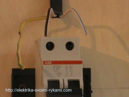 Remove the second layer of insulation from the phase and neutral wires, about 1 centimeter.
We twist the contact screws and insert the wires into the contacts of the machine. On the left we connect a phase wire, and on the right it is zero. The outgoing wires must be connected in the same way. After connection, be sure to check again. Care must be taken to ensure that the clamping contact does not accidentally get wire insulation, because because of this, the copper wire will have a bad pressure to the contact of the machine, from which the wire will warm up, the contact will burn, and the result will be the failure of the machine.
Inserted the wires, tightened with a screwdriver screws, now you need to make sure of a reliable fixation of the wire in the contact clamp. We check each wire separately, slightly swing it to the left, to the right, pulling up from the contact, if the wire is still, the contact is good.

In our case, a three-wire wire is used, in addition to the phase and zero there is a core earthing . It is by no means connected via a circuit-breaker, for it a through contact is provided. Inside, it is connected by a metal bus, so that the wire without a rupture passes to the final destination, as a rule it is the outlet.

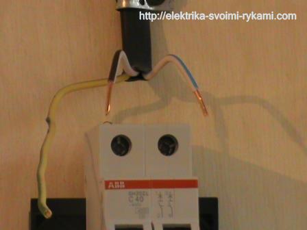
If you do not have a contact hole at hand, you can simply twist the incoming and outgoing strand with each other by ordinary twisting, but in this case it must necessarily be well stretched with pliers. An example is shown in the picture.

The access contact is installed as easily as the machine, it snaps onto the rail with a slight movement of the hand. We measure the necessary amount of ground wire, bite off excess, remove the insulation (1 centimeter) and connect the wire into contact.

Do not forget to make sure the wire is properly fixed in the contact clamp.

Suitable wires are connected.
In the event of the operation of the automaton, the voltage remains only on the upper contacts, this is completely safe and is provided by the circuit for connecting the circuit breaker. The lower contacts in this case will be in complete discontinuity from the electric current.
We connect the outgoing wires. By the way, these wires can go anywhere to the light, the outlet or directly to the equipment, for example, an electric water heater or an electric stove.
We remove the external insulation, we measure the amount of wire necessary for connection.


We remove the insulation from the copper veins and connect the wires to the machine.


Prepare the ground wire. We measure the right amount, clean it, connect it. We check the reliability of the fixation in the contact.
![]()

The connection of the circuit breaker has come to its logical conclusion, all the wires are connected, it is possible to apply voltage. At the moment the machine is in the off position down (off), we can safely apply voltage to it and turn it on, for this we move the lever to the up (on) position.

Install and correctly connect the machine in the switch cabinet - no problem. This can be handled even by an ordinary person who only encounters electricity when inserting a plug from the household appliance into the outlet or switching on the lighting. But the question of how to properly connect the machine, still often sounds from the townsfolk. The whole point is that even among electricians there are disputes about the ways of connection. That is, bring the supply wire to the circuit breaker from above or below.
Let's not argue here, but just turn to the rules for the installation of electrical installations (PUE), where in one of the items, or, more precisely, in paragraph 3.1.6, everything is clearly described. No photo below is an extract from this item of the PUE. 
So, the rules recommend to connect the supply wire to a stationary contact in the machine. And it is located exactly from above. But let's be honest until the end, and once again read the rule. In it there is no strict limitation, that is, it has only a recommendatory character. Therefore, when answering the question of how to connect the circuit breaker from below or from above, you can use two options. Moreover, the device will disconnect the network from overloads and short circuits in any case, regardless of the connection scheme.
And yet, why is this item present in the PUE? To answer this question, it is necessary to consider the circuit-breaker device.
To go to the circuit connection of the machine, you need to understand first of all with its design. And since we are interested in connecting wires to the lower or upper contacts of the device, it should be understood that both contacts (movable and fixed) are made of different metal alloys.
When it comes to AC power, when switching the machine its contacts burn out evenly, and there's no difference where to connect the wires. If the machine is located in a circuit with a constant current, the selection of the connection contact is an important component of the correct and long-term operation of the device itself. With a high value of current strength, the transfer of metals from one contact to another is observed, therefore, in such networks, the connection of the supply wires must be made only from above, that is, through a fixed contact.
Now go directly to the device itself. In order to understand what is inside this device, we recommend that you familiarize yourself with the figure below.
The two main elements that perform the protective functions of the machine are electromagnetic and thermal releases.
Electromagnetic release
This element is protective, which works if there is a short circuit in the electrical circuit where the machine itself was installed. It is at this point in the circuit that currents of enormous magnitude appear (almost exceeding the nominal current value by thousands of times). In order not to burn the wiring and household appliances included in the sockets, the release instantly disconnects the feeder network. The shutdown time is milliseconds. By the way, there is a certain marking on the time-current characteristics. It is denoted by the letters of the Latin alphabet and is applied to the body of the circuit breaker itself. In everyday life the types "A", "B", and "C" are more often used.
The very design of the electromagnetic release is the core (solenoid) around which the coil springs are arranged. The solenoid is connected directly to the movable contact of the machine. But the spring is connected in series with the power contacts and the thermal release. The rated current is too small for the magnetic flux created inside the coil to retract the core and thereby open the contacts. As soon as there is a short circuit in the network, that is, a huge tag appears, inside the coil (spring) there are large magnetic fluxes, the spring contracts and draws in itself the core, which in turn immediately opens the power contacts. And, therefore, the network will be de-energized.

This element is intended to protect the electrical circuit if large loads other than the rated load are acting in it. This is a release, so to speak, delayed action. It will have a certain time to hold the overload, and if the latter does not drop to the nominal value, it will turn off the power. Immediately make a reservation that the thermal release will not react to short-term current jumps.
The purely thermal design of the thermal release is a bimetallic plate, which, in fact, is a console. Its free end is connected to a mechanism that will disconnect the contacts. At rated current, the free end of the plate is located close to the release mechanism lever. As soon as the circuit starts to overload, the plate begins to heat up and flex, thereby acting on the lever, which in turn is on the mechanism, and the latter on the contacts, opening them.
Here is a rather complicated circuit breaker device and the principle of operation.

Connection diagrams
So, the principle of the circuit breaker is now clear, you can go directly to its connection diagrams. To begin with, automata can be connected to single-phase and three-phase networks. What kind of machines are needed for this? If the conversation is from single-phase networks with a voltage of 220 volts, they usually have either a single-pole device or a two-pole device. The circuit itself will depend on whether the ground loop is used in it or not.
If the house includes two wires (zero and phase), then in the switch cabinet you can put a single-pole version. In this case, the phase contour will pass through the automaton itself. If inside the house there are three wires (phase, zero and ground), then the general machine should be bipolar. That is, the phase is connected to the first terminal of the device, to the second zero. Grounding through a separate terminal box is bred to consumers (lights and sockets). Further, the wires from the circuit breaker are held up to the counter, then to single-pole machines, installed in groups, but already as described in the first case. By the way, here is the given system of connecting the machine.

As for the three-phase network, in this case it is best to put three-pole or four-pole designs. Here everything is exactly the same as in the case of single-phase connection. That is, if the house uses wiring without grounding, then three phases of the mains are connected to the fixed contacts. Zero wire is bred as a separate circuit to consumers (sockets and lamps). If there is a ground system in the house, a four-pole model is installed, that is, three phases and zero will be connected to the device, and the ground loop will go to a separate line to consumers.
Sometimes the connection of the circuit breaker is connected with the correct conduct of certain nuances of the entire process. Namely, the connection of wires to the device. What should I pay attention to?
- Each model has its own requirements regarding the cross-section of the inserted wire and the length of the insulation shell. This must be indicated in the product passport.
- Most often, the wire must be stripped to a length of 0.8 to 1.0 cm.
- It is important to understand that it is not permissible to place an insulated wire in the terminal, because the insulation diameter is larger than the diameter of the core itself, so that the contact between the clamp and the housing is either weak or completely absent.
- Fixing the wire in the machine is made by screw, which is screwed with a screwdriver. After fixing, it is necessary to check the quality of the clamp, for this purpose the wire itself needs to be slightly twitched.
- If a multicore conductor is used to connect the machine, then it is best to put the tip on its end.

Conclusion on the topic
So, in this article we tried to answer a question that interests many, how to connect the machine correctly? We hope that everything is clear from the information provided. And as already mentioned above, this process is not the most difficult, the main thing is to understand the connection schemes.
Similar entries: