Resistor - a passive element of an electrical circuit having a unique characteristic-resistance. The name of the resistor was derived from the Latin resisto-"I resist". Therefore, a resistor is often called simply resistance. From the article you can learn a little useful theory about resistance, learn to understand the marking of resistors, including color.
Before reading the article, you can immediately order a set of 600 pieces of the most popular resistors (30 denominations of 20 each) for link or a good extended set of 820 resistors (41 denominations of 20 each) here
What is resistance?
The electric current flowing through the wires is resisted. This resistance varies depending on the external conditions and properties of the conductor. The thinner the wire, the greater the resistance. The longer the wire, the greater the resistance. If you have already gone ten kilometers, then it becomes harder to go than at the beginning of the journey. This comparison is not entirely correct from the point of view of physics, but allows us to represent the above-described properties of conductors.
Resistors in bulk. Mostly Soviet.
The amount of resistance depends on the following factors:
- From the length of the conductor
- From the conductor temperature
- From the cross-sectional area (thickness) of the conductor
- From the material from which the conductor is made
- On the strength of current
- From the voltage

The unit of resistance is-Ohm. Named after the German physicist Georg Oma. This is the same Om, who formulated ohm's law , without which you can not do with the calculation of any scheme. The physical meaning of one Ohm is this: the conductor has a resistance of 1 Ohm, if the current that flows through this conductor is 1 A (Ampere), and the voltage applied to the ends of this conductor is 1 V (Volts). The device for measuring resistance is called an ohmmeter.

The ohmmeter. The device for measuring resistance.
Types of resistors
A large number of resistors of various standard values are available from units to millions of Ohms. It is useful to know the ratio of the resistance values:
1 KΩ (kilo) = 1000 ohms
1 MΩ (megawatt) = 1000 KΩ = 1,000,000 Ohm
Resistors are of three types:
- Constant
- Variables
- Trimming
The most numerous class is constant resistor-resistors, whose resistance can not be changed. Therefore, they are called permanent. Variable resistor- »twist». They are used, for example, to adjust the volume. Trimmer resistor is also a variable resistor, but made in a more compact package. From the variable, it differs mainly in that it is not designed for frequent changes in resistance. If you often twist the tuning resistor, it will quickly fail. Designed for installation where you need a configurable resistance, but it must be adjusted once (when manufacturing the board in the factory). Trimmer resistors are used, for example, in radio receivers. Naturally, a lot of resistors are produced, differing from each other in different parameters. In order to understand the characteristics of the resistor, its parameters are noted directly on the body. How exactly the resistors are marked and we'll talk further.

Constant resistors
Color marking and other methods of denoting the resistor value
When they say "resistor rating", they mean "resistance of the resistor". Further in the text you will meet both terms. Why there was such a "duality" will be described below. The old resistors were quite large, so all the denominations were indicated by the usual letters on the cases of these resistors. But if you get such a resistor in your hands, you will hardly be able to determine its resistance at once, the resistance there is not indicated "on the forehead". In addition, the resistor indicated not only its resistance, but also some other parameters. In order to understand this, consider the characteristics of the constant resistors. Resistors are characterized by the following properties:
- Resistance
- Accuracy class (tolerance)
- Power Dissipation
Next, let's talk about these properties and find out how they are indicated on the resistor case. Resistance is the main characteristic of the resistor (for the sake of resistance it is set). We have already briefly discussed what resistance is, at the beginning of the article, so we will immediately go over to its designation. Running forward, I will say that if you came here to learn how to "read" the colored strips on the resistor housing-proceed to reading immediately from the header "Color marking of resistors". Because now we are learning to mark the marking of domestic resistors for a better understanding of the essence.
If the resistance is less than 1000 Ohm:
In this case, after the number that indicates the resistance value, they write the letter R. Or they do not write any letter at all. On some old Soviet-made resistors, you can see the word Om. Later, the resistors began to apply the following symbols: first the whole part of the number, then the letter R, and then the fractional part of the number.
Examples of resistance designations:
100 = 100 Ω
100 R = 100 Ohm
More recent (modern) notation:
1R5 = 1.5 Ohm
1R0 = 1 Ohm
0R2 = 0.2 Ohm
If the first digit is 0, then it is usually not written, therefore:
0R2 = R2 = 0.2 Ohm
If the resistance is greater than 1000 Ohm:
In this case, not to write large numbers, use the kilo and megaohms. In fact, there are also more powerful prefixes, for example, Giga- and Tera-, but such large resistances in electronics practically do not occur, so we limit ourselves to kilo and megaohms. The principle of writing values remains the same, just changing the letters, and, consequently, the values of the resistances. Examples:
K100 = 100 Ohm
1K0 = 1 KΩ = 1000 Ohm
1K5 = 1.5 KOM = 1500 Ω
M220 = 0.22 MΩ = 220 KΩ = 220,000 Ω
1M0 = 1 MOhm = 1000 KΩ = 1,000,000 Ohm
3M3 = 3.3 MOhm = 3300 KΩ = 3 300 000 Ohm
This is all you need to know about the designation of resistance. We can discuss the following characteristic.
Accuracy class of the resistor
How to make a resistor? You can take an ohmmeter, a piece of wire and use an ohmmeter to measure the resistance of a piece of wire of a certain length. For example, the resistance of a centimeter piece of nichrome wire. Then measure the length that will give us the proper resistance and use this piece as a resistor. Approximately so everything happens in industry. Only instead of wire, films of special materials are used, but the essence remains the same - the length (width, thickness, mass) of a certain material is known, which needs to be packed into the case to obtain the necessary resistance. But this material also needs to be produced somewhere, cut into something, move somewhere. All these processes affect the resistance of the material. Therefore, it is difficult to make all the resistors absolutely identical - for various reasons there is a spread of parameters. And if so, all the resistance values are nominal parameters, which in reality differ slightly in one direction or another. Therefore, they say "resistor value" instead of "resistor resistance". The magnitude of these differences determines the accuracy class (tolerance). Tolerance is measured in percent.
Example: Resistor 100 Ω +/- 5%
This means that the resistance of a real resistor can differ by five percent from the nominal value. Remember the elementary school: in our case, 100 Ohm is 100%, then 5% is 5 Ohms.
100 – 5 = 95; 100 + 5 = 105
That is, the value of a particular resistor can "walk" in the range from 95 to 105 Ohm. For most circuits this is insignificant. But in some cases it is necessary to choose a more accurate resistance - then choose a resistor with a higher accuracy class. That is not 5%, but, for example 2%.
On old resistors, the tolerance is as follows: 20%, 10%, 5%, etc. But there is also an alphabetic character set. If the resistor is denominated in a letter, the last letter (if any) indicates the tolerance value. The values of these letters are given in the table:
| Letter | B | C | D | F | G | J | K | M | N |
| Tolerance | 0,1% | 0,25% | 0,5% | 1% | 2% | 5% | 10% | 20% | 30% |
Examples:
1K5K = 1.5 KΩ 10%
1K0M = 1 KΩ 20%
1K05V = 1.05 KΩ 0.1%
Power dissipation resistor
In physics, the power of the electrical current is denoted by the letter P. Power is measured in watts (denoted by W or W). Depends on the power of the current and voltage and for DC is calculated by the formula:
If a large current does not flow through the resistor, then you can use a resistor of any power - nothing will happen to it. But if a significant current flows through the resistor, it can overheat and fail (simply burn). Therefore, it is worth calculating the power that will be allocated to the resistor - the power dissipation. Power is written on the resistor case either Roman or Arabic numerals. On low-power resistors power is usually not indicated.
Examples of notation:
1 W = 1 Watt
IV W = 4 W
2 W = 2 Watts
V W = 5 W
We have considered the method of designating resistors that was used before. Modern resistors label differently. The old method was not very convenient, but the resistor's denomination with such a way of designation can be understood without any directories. However, I had to make everything worse. Modern equipment is small in size, and therefore the components that are used in it, must also have a minimum size. Resistors are needed small and, despite the fact that modern technology allows you to put an inscription on them, you will not be able to make out this inscription afterwards. Therefore, the color marking of the resistors was developed.
Color marking of resistors
The color marking is applied to the resistor in the form of four or five color strips. Resistors with four colored strips, the first and second denote the resistance in ohms. The third is the multiplier, to which the resistance value must be multiplied. The fourth band defines the accuracy class in percent. Resistors with five bands are resistors with a small tolerance (0.1% - 2%). The first three bands are the resistance value, the fourth is the multiplier, the fifth is the tolerance. Each color has its own number. It is important to choose the right order in which we will read the colors. Color rings on the resistors are shifted to one of the leads and are located from left to right. If the resistor is too small and there is no possibility to move the marking to one of the leads, then the first strip is made approximately twice as thick as the others. But on some resistors these rules are not observed. In this case, you can only guess. The marking feature will help us guess: silver, gold and black colors define the tolerance class of the resistor. Hence, the strips of these flowers are never the first. Therefore, if
one of these colors (except black) is applied from any edge, then this edge is right. Also orange, yellow and white are never the last. So, if one of these colors is applied from any edge, then this is the left edge.
Table for decoding the color marking of the resistor:
| Ring color or dots | First digit | The second figure | Factor | Tolerance,% | ||
| The black | — | 0 | *1 | 1 | — | |
| Brown | 1 | 1 | *10 | 10 | 1% | |
| Red | 2 | 2 | *100 | 10 2 | 2% | |
| Orange | 3 | 3 | *1.000 | 10 3 | — | |
| Yellow | 4 | 4 | *10.000 | 10 4 | — | |
| Green | 5 | 5 | *100.000 | 10 5 | 0,5% | |
| Blue | 6 | 6 | *1.000.000 | 10 6 | 0,25% | |
| Purple | 7 | 7 | *10.000.000 | 10 7 | 0,1% | |
| Gray | 8 | 8 | *100.000.000 | 10 8 | 0,05% | |
| White | 9 | 9 | *1.000.000.000 | 10 9 | — | |
| Golden | — | — | *0,1 | 10 -1 | 5% | |
| Silver | — | — | *0,01 | 10 -2 | 10% | |

You can practice determining the denomination in this picture.
There are also resistors designed for surface mounting (SMD). Such resistors are so small that even colored stripes can be placed on them problematically. The marking of resistances on them is customarily applied in a different way. The encoded value consists of three or four digits. The last digit indicates the degree of the number ten, that is, simply the number of zeros that must be assigned to the first digits to get the value in ohms.
103 is the last digit of 3, then we assign three zeroes to number 10, we get 10 000 Ohm = 10
Kom.
1562 - the last digit 2, then to the number 156 we assign two zeroes, we get 15600 Ohm =
15.6 Kom.
If the last digit is zero, then the first digit is the nominal value. For example, if the resistor is labeled "100", then we assign 0 to 0, we get 10 ohms.

SMD resistor 47kΩ

After reading the article, we learned what resistors are for, what are the markings on resistors, and how to determine the resistance of the resistor. Now it's time to start using these devices in real circuits.
There are other articles that will help you learn how to correctly use a resistor in real electrical circuits:
Buy a set of 600 pieces of the most popular resistors (30 denominations of 20 each) for link or here's another good set of 820 resistors (41 denominations of 20 each) here.
I also collect a large list of proven sellers. You can familiarize yourself.
Conductors exert an electrical resistance, the greater this resistance, the less the electric current through the conductor. The resistance of the conductor depends on the material of which it consists, length, section, temperature. The longer the conductor, the greater the resistance, the shorter the conductor, the less resistance. The thinner the conductor, the more resistance the thicker the conductor, the less resistance.
Resistance is denoted by the letter R, and the unit of resistance - in letters Om. In practice, there are also units of electrical resistance with a kilo kOhm) and mega ( MΩ).
1 kΩ = 1000 Ohm
1 MΩ = 1,000,000 Ohm
To find the resistance of the conductor in ohms, it is necessary to divide the voltage at its ends in volts by the current in amperes:
Constant resistors
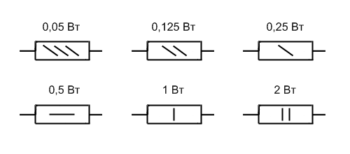
A resistor is a passive element of an electrical circuit. Serves to reduce the amperage, during operation, the resistors are heated, because excess electrical energy is converted by resistors into heat. On electrical circuitry, the resistors are displayed as a rectangle with two terminals or as a broken line (American standard), denoted by the letter R with the serial number (R1, R2, etc.). The resistor value is indicated next.
![]()
The main parameter of the resistor is resistance. Resistor resistance is measured in ohms, kilohms, megaohms. The nominal dissipation power of the resistor (from 0.05 to 5 W) is indicated by special signs placed inside the symbol.
Marking of resistors. According to GOST 2.702-75, the resistance from 0 to 999 Ohm indicates on the diagrams a number without a unit of measurement (3.3, 47, 220, 750, etc.), from 1 to 999 kΩ - a number with the letter k (47 k, 330 k; 910 k, etc.), more than 1 megaohm - a number with the letter M (1 M, 4.7 M, etc.).
According to GOST 11076 - 69 units of resistance in the coded system are denoted by the letters E or R (Ohm), K (kilo) and M (mega). So 33 ohms mark 33E, 1 Ohm - 1R0, 47 Ohm - 47E, 10k ohm - 10K, 47k ohm - 47K, and so on.
Resistances from 100 to 1000 Ohm and from 100 to 1000 kOhm are expressed in fractions of a kilo and a megaohm respectively, and in the place of zero and a comma set the corresponding unit of measurement: 150 Ω = 0.15 kΩ = K150; 910 Ohm = 0.91 kΩ = K91; 180 kΩ = 0.18 MΩ = M18; 680 kOhm = 0.68 MOhm = M68, and so on.
If the nominal resistance is expressed as an integer with a fraction, then the unit of measure is put in place of a comma: 3.3 ohms - 3E3 or 3R3; 4.7 кОм - 4К7; 3.3 MΩ - 3 M3, and so on.
SMD resistors and trimmers can be labeled with three digits, the first two denote resistance in ohms (mantissa), and the third one - the number of subsequent zeros (the exponent on the base 10), and the letter R. can be added to the marking for the decimal point. Examples:
Marking 513 means 51 x 10 3 = 51,000 ohms or 51 kOhm
The marking R470 means 0.47 Ohm
There are still a lot of markings with colored stripes, but manufacturers of resistors do not adhere to the general standard, so it's more reliable to measure the resistance of the resistors with a multimeter.
Variable resistors
Variable resistors are resistors whose resistance can be changed. They are used as gain, volume, tone, etc. controls.

There are two schemes for including variable resistors in an electrical circuit. In one case, they are used to regulate the current in the circuit, and then the adjustable resistor is called a rheostat. In another case, they are used to control the voltage, then the resistor is called a potentiometer.
Trimmer Resistors
A kind of variable resistors - trim. The control unit of such resistors is adapted for controlling the screwdriver.

Connecting Resistors
When the resistors are connected in series, their resistance is added:

With parallel connection, the total resistance is calculated by the formula:

If two identical resistors are connected in parallel, the total resistance will be equal to half the resistance of one of them.
In this way, you can obtain the required resistor ratings from the available ones.
Resistors are the most common elements of radio electronic equipment. Previously, resistors were called resistors, but according to the State Standard, electrical resistances, like circuit elements, are named "resistors".
This was done to distinguish between "resistance" as a product (radio component) and "resistance", as its physical property, electrical quantity. Resistors are characterized by electrical resistance.
The basic unit of electrical resistance in accordance with the international system of units is Om. In practice, also the derived units are used - kilo (kOhm), mega (MOhm), giga (GOhm), terahom (TOM), which are related to the basic unit by the following relationships:
- 1 kΩ = 10 ^ 3 Ohm,
- 1 MΩ = 10 ^ 6 Ohm,
- 1 GΩ = 10 ^ 9 Ohm,
- 1 TH = 10 ^ І2 Ohm.
The following types of resistors: permanent and variables. The variables are still divided into adjusting and trim. For permanent resistors, the resistance can not be changed during operation.
Resistors, through which various adjustments in radio electronic equipment are carried out by changing their resistance, are called variable resistors or potentiometers. Those resistors , whose resistance is changed only during the adjustment (adjustment) of the electronic device, is called trimming.
Basic parameters of resistors
Resistors are characterized by such basic parameters as the nominal value of the resistance, the permissible deviation of the resistance from the nominal value, the nominal (permissible) dissipation power, the maximum operating voltage, the temperature coefficient of resistance, own noise and the voltage coefficient.
The nominal value of the resistance R is usually indicated on the resistor housing. The actual value of the resistance of the resistor can differ from the nominal within the permissible deviation (tolerance, determined in percentage of the nominal resistance).
Marking of resistors
Typically, the resistor is painted with paint type, nominal power, nominal resistance, tolerance and production date. For marking small-size resistors use an alphanumeric code. The code consists of digits denoting the nominal resistance, a letter denoting the unit of measurement, and a letter indicating the permissible deviation of the resistance. Examples of the letter code of the units of the nominal resistance of the old and new standards applied to the case of the resistor are given in Table. 1.
If the nominal resistance is expressed as an integer, then the letter code is placed after this number. If the nominal resistance is a decimal fraction, the letter is put instead of a comma, dividing the whole and fractional parts. In the case when the decimal fraction is less than one, the whole part (zero) is excluded.
When marking the resistors, the tolerance code is placed after the encoded designation of the nominal resistance. The letter tolerance codes are listed in Table. 2.
For example, the designation 4K7B (or 4K7M) corresponds to a nominal resistance of 4.7 kΩ with an acceptable deviation of 20%. In Table. Figures 1 and 2 show letter codes corresponding to both old and new standards, since both variants are currently encountered. Nominal power on small-size resistors is not indicated, but is determined by the dimensions of the housing.
Table 1. Designation of the nominal value of resistance on the resistor housings.
| Full designation | Abbreviated designation on the body | |||||
| Notation | Examples of designation | Units of measurement | Examples of designation | |||
| units of measurement | Old | New | Old | New | ||
| Om | Omaha | R | E | 13E 470E (K47) | ||
| kOhm | kilo | TO | TO | |||
| MΩ | mega-ohms | 470 MΩ | M | M | M47 | |
Table 2. Letter codes for tolerances of resistances applied to the case of resistors.
Color code of the marking of resistors
The type of marking in which the resistor is applied to the body in the form of colored rings or dots is called the color code (see Figure 1). Each color corresponds to a certain numerical value.
The color marking on the resistors is shifted to one of the leads and read from left to right. If the marking can not be placed on one of the leads, then the first sign is made by a strip two times wider than the others.
For resistors with a small tolerance (0.1 ... 10%), the marking is made by five color rings. The first three rings correspond to the numerical value of the resistance in ohms, the fourth ring has a multiplier, and the fifth ring - tolerance (Figure 1).
Resistors with a tolerance of 20% are marked with four colored rings and no tolerance is applied on them. The first three rings are the numerical value of the resistance in ohms, and the fourth ring is the multiplier. Sometimes resistors with a tolerance of 20% are labeled with three colored rings.
In this case, the first two rings are the numerical value of the resistance in ohms, and the third ring is the multiplier. The non-zero zero in the third digit is not marked.
Due to the fact that in the market of radio equipment a significant place is occupied by foreign products, we note that resistors of foreign companies are marked with both digital and color code.
When digitally labeled, the first two digits represent the numerical value of the resistor value in ohms, and the remaining ones represent the number of zeros. For example: 150 - 15 Ohms; 181 - 180 Ohm; 132 - 1.3 kOhm; 113-11 kOhm.
Color marking is usually made up of four color rings. The resistance rating represents the first three rings, two digits and a multiplier. The fourth ring contains information on the permissible deviation of the resistance from the nominal value in percent.
The determination of the values of the foreign resistors by the color code is the same as for the domestic ones. Tables of color codes of domestic and foreign resistors coincide.
Many companies, in addition to traditional labeling, use their internal color and code markings. For example, there is a marking of SMD-resistors, when instead of the number 8 a colon is put. So, marking 1:23 means 182 kOhm, and 80R6 - 80,6 Ohm.
| Color of rings or dots | Rated resistance, Ohm | Factor | Tolerance,% | ТКС,% / ГС | ||
| 1st digit | 2nd digit | The third digit | 4th digit | 5th digit | p | |
| Silver | - | - | - | 0601 | ± 10 | - |
| Golden | - | - | - | 061 | ± 5 | - |
| The black | - | 0 | - | 1 | - | - |
| Brown | 1 | 1 | 1 | 10 | ± 1 | 100 |
| Red | 2 | 2 | 2 | 10^2 | ± 2 | 50 |
| Orange | 3 | 3 | 3 | 10^3 | - | 15 |
| Yellow | 4 | 4 | 4 | 10^4 | - | 25 |
| Green | 5 | 5 | 5 | 10^5 | ± 0.5 | - |
| Blue | 6 | 6 | 6 | 10^6 | ± 0.25 | 10 |
| Purple | 7 | 7 | 7 | 10^7 | ± 0.1 | 5 |
| Gray | 8 | 8 | 8 | 10^8 | ± 0.05 | - |
| White | 9 | 9 | 9 | 10^9 | - | 1 |
Fig. 1. Color marking of domestic and foreign resistors in the form of rings or points, depending on the tolerance and TKE.
Literature: V.M. Pestrikov. Encyclopedia of radio amateurs.
The term resistance in some respects was more fortunate than other physical terms: we have been acquainted with this property of the surrounding world since the early childhood, mastering the habitat, especially when we are drawn to a toy in the hands of another child, and he resists it. This term is intuitively clear to us, therefore in school days during physics lessons, getting acquainted with the properties of electricity, the term electrical resistance does not cause us any confusion and its idea is perceived quite easily.
The number of technical implementations of electrical resistance in the world - resistors - can not be calculated. Suffice it to say that in the most widespread modern electronic devices - mobile phones, smartphones, tablets and computers - the number of elements can reach hundreds of thousands. According to statistics, resistors account for more than 35% of electronic circuit elements, and given the scale of production of such devices in the world, we get an astounding figure of tens of trillions of units. Along with other passive radio elements - capacitors and inductors, resistors lie at the heart of modern civilization, being one of the whales on which our familiar world rests.

Definition
Electrical resistance is a physical quantity characterizing some electrical properties of matter to prevent free, without loss, passage of an electric current through it. In terms of electrical engineering, electrical resistance is the characteristic of the electrical circuit as a whole or of its section to impede the flow of current and equal, at a constant current, the ratio of the voltage at the ends of the circuit to the current flowing through it.
Electrical resistance is associated with the transfer or conversion of electrical energy into other types of energy. With the irreversible transformation of electrical energy into thermal energy, we are talking about active resistance. In reversible conversion of electrical energy into magnetic or electric field energy, if an alternating current flows in the circuit, the reactance is said to be. If the inductance predominates in the circuit, it is said about the inductive resistance, if the capacitance is about the capacitive resistance.
The impedance (active and reactive) for AC circuits is described by impedance concepts, and for variable electromagnetic fields by impedance. The resistance is sometimes not quite rightly called its technical implementation - a resistor, that is, a radio component intended for the introduction into the electrical circuits of active resistance.
Resistance is denoted by the letter R or r and is considered, within certain limits, a constant value for a given conductor; it can be calculated as

R - resistance, Ohm;
U - difference of electrical potentials (voltage) at the ends of the conductor, V;
I is the strength of the current flowing between the ends of the conductor under the action of the potential difference, A.
This formula is called Ohm's law, after the German physicist who discovered this law. An important role in the calculation of the thermal effect of the active resistance is played by the law on the heat released when an electric current passes through the resistance-the Joule-Lenz law:
Q = I 2 ∙ R ∙ t
Q is the amount of heat released during the time interval t, J;
I is the current strength, A;
R - resistance, Ohm;
t - time of current flow, sec.

Units
The basic unit of measurement of electrical resistance in the SI system is Om and its derivatives: kilo (kOhm), mega (MOhm). The ratio of SI resistance units to units of other systems can be found in our unit converter.
Historical reference
The first researcher of the phenomenon of electrical resistance, and, subsequently, the author of the famous law of the electrical circuit, later named after him, became the outstanding German physicist Georg Simon Om. Published in 1827 in one of his works, Ohm's law played a decisive role in the further study of electrical phenomena. Unfortunately, contemporaries did not appreciate his research, like many of his other works in physics, and, on the instruction of the Minister of Education for publishing the results of his research in the newspapers, he was even dismissed as a mathematics teacher in Cologne. And only in 1841, after being awarded to him by the Royal Society of London at a meeting on November 30, 1841, Medal Copley, finally comes to him a confession. Considering the merits of George Ohm, in 1881, at an international congress of electricians in Paris, it was decided to call his now-common unit of electrical resistance ("one ohm").
Physics of the phenomenon in metals and its application
By their properties of the relative value of resistance, all materials are divided into conductors, semiconductors and insulators. A separate class is materials having zero or close to such resistance, the so-called superconductors. The most characteristic representatives of conductors are metals, although their resistance can vary within wide limits, depending on the properties of the crystal lattice.
According to modern concepts, metal atoms are combined into a crystal lattice, while the so-called "electron gas" is formed from the valence electrons of metal atoms.

The relatively small resistance of metals is due precisely to the fact that they have a large number of current carriers-conduction electrons-belonging to the entire ensemble of atoms of a given metal sample. Arising when an external electric field is applied, the current in the metal is the ordered motion of the electrons. Under the action of the field, the electrons are accelerated and acquire a certain momentum, and then collide with the lattice ions. In such collisions, the electrons change the momentum, partially losing their energy of motion, which is converted into the internal energy of the crystal lattice, which leads to the heating of the conductor as the electric current passes through it. It should be noted that the resistance of a sample of metal or metal alloys of a given composition depends on its geometry, and does not depend on the direction of the applied external electric field.
The further application of an increasingly strong external electric field leads to an increase in the current through the metal and the release of an increasing amount of heat, which, ultimately, can lead to the melting of the sample. This property is used in wire fuses for electrical circuits. If the temperature exceeds a certain rate, the wire melts, and interrupts the electric circuit - no more current can flow through it. The temperature norm is provided by choosing the material for the wire at its melting point. A perfect example of what happens to fuses, gives the experience of filming the burning of a filament in a conventional incandescent lamp.
The most typical application of electrical resistance is its use as a fuel element. We use this property when cooking and heating food on electric stoves, baking bread and cakes in electric furnaces, as well as working with electric kettles, coffee machines, washing machines and electric irons. And we do not think at all that our comfort in everyday life, again, should be grateful to the electrical resistance: whether the shower is turned on, or the electric fireplace, or the air conditioner is in the warm-up mode of the air in the room - all these devices necessarily have a heating element based on electric resistance.
In industrial applications, electrical resistance provides preparation of food semi-finished products (drying), chemical reactions at the optimum temperature for the production of dosage forms and even for the manufacture of absolutely prosaic things, like polyethylene bags for various purposes, and also for the production of plastic products (extrusion process).
Physics of the phenomenon in semiconductors and its application
In semiconductors, unlike metals, the crystal structure is formed due to covalent bonds between the atoms of the semiconductor and therefore, in contrast to metals, in pure form they have a much higher electrical resistance. Moreover, if one speaks of semiconductors, one usually refers not to resistance, but to intrinsic conductivity.

The introduction of impurities into the semiconductor atoms with a large number of electrons on the outer shell, creates a n-type donor conductivity. In this case, the "extra" electrons become the property of the entire ensemble of atoms in a given sample of the semiconductor and its resistance decreases. Similarly, the introduction into the semiconductor of impurities of atoms with a smaller number of electrons on the outer shell, creates an acceptor conductivity of the p-type. In this case, the "missing" electrons, called "holes", become the property of the whole ensemble of atoms in a given sample of the semiconductor and its resistance also decreases.
The most interesting case is the connection of regions of a semiconductor with different types of conductivity, the so-called p-n junction. Such a transition has a unique property of anisotropy - its resistance depends on the direction of the applied external electric field. When the "closing" voltage is switched on, the boundary layer of the p-n junction is depleted by the conductivity carriers and its resistance increases sharply. When the "opening" voltage is applied in the boundary layer, conductivity carriers are recombined in the boundary layer and the resistance of the p-n junction is sharply reduced.
On this principle, the most important elements of electronic equipment are constructed: rectifying diodes. Unfortunately, when a certain current exceeds a p-n junction, a so-called thermal breakdown occurs, in which both the donor and acceptor impurities move through the p-n junction, thereby destroying it, and the device breaks down.
The main conclusion about the resistance of p-n junctions is that their resistance depends on the direction of the applied electric field and is non-linear, that is, it does not obey Ohm's law.
A somewhat different character is the processes occurring in MOSFETs (Metal-Oxide-Semiconductor). In them, the resistance of the source-drain channel is controlled by the electric field of the corresponding polarity for the p- and n-type channels created by the gate. MOSFETs are almost exclusively used in key mode - "open-close" - and make up the overwhelming number of electronic components of modern digital technology.
Regardless of the performance, all transistors in their physical essence are, within certain limits, inertial-controlled electrical resistance.

Physics of the phenomenon in gases and its application
In the ordinary state, gases are excellent dielectrics, since they contain a very small number of charge carriers-positive ions and electrons. This property of gases is used in contact switches, overhead power lines and in air condensers, since air is a mixture of gases and its electrical resistance is very high.
Since the gas has ion-electron conductivity, when the external electric field is applied, the resistance of the gases first decreases slowly due to the ionization of an increasing number of molecules. With a further increase in the external field voltage, a glow discharge occurs and the resistance goes over to a steeper voltage dependence. This property of gases was previously used in gas-filled lamps - stabilizers - to stabilize a constant voltage over a wide range of currents. With further growth of the applied voltage, the discharge in the gas passes into the corona discharge with a further decrease in the resistance, and then in the spark - a small lightning arises, and the gas resistance in the lightning channel drops to a minimum.

The main component of the radiometer-dosimeter Terra-P is geiger-Mueller counter . His work is based on the shock ionization of the gas contained in it when a gamma quantum hits, as a result of which its resistance decreases sharply, which is recorded.
The property of gases to glow when the current flows through them in the glow discharge mode is used to design neon advertisements, display alternating fields and sodium lamps. The same property, only when glow of mercury vapor in the ultraviolet part of the spectrum, provides work and energy-saving lamps. In them the light flux of the visible spectrum is obtained as a result of the conversion of ultraviolet radiation by a fluorescent phosphor coated with bulb lamps. The resistance of gases, just like in semiconductors, has a non-linear dependence on the applied external field and also does not obey Ohm's law.
Physics of the phenomenon in electrolytes and its application
The resistance of conducting liquids - electrolytes - is determined by the presence and concentration of ions of various signs - atoms or molecules that have lost or attached electrons. Such ions, when electrons are deficient, are called cations, with an excess of electrons-anions. When applying an external electric field (placing electrolyte electrodes with a potential difference), the cations and anions move; The physics of the process consists in discharging or charging ions at the corresponding electrode. At the same time, the anions are emitted by excessive electrons, while cathodes receive the missing ones.

A significant difference between electrolytes from metals, semiconductors and gases is the movement of matter in electrolytes. This property is widely used in modern technology and medicine - from metal purification from impurities (refining) to the introduction of drugs into the diseased region (electrophoresis). The sparkling plumbing of our baths and kitchens is due to the processes of electroplating - nickel plating and chrome plating. Needless to say, the quality of the coating is achieved precisely by controlling the resistance of the solution and its temperature, as well as many other parameters of the metal deposition process.
Since the human body is an electrolyte from the physical point of view, knowledge of the resistance of the human body to the flow of an electric current plays an important role in relation to safety issues. Although the typical value of skin resistance is about 50 kOhm (weak electrolyte), it can vary depending on the psychoemotional state of the individual and the environmental conditions, as well as the skin contact area with the electric current conductor. With stress and excitement or in uncomfortable conditions, it can be significantly reduced, so the value of 1 kOhm is assumed to calculate human resistance in safety engineering.
It is curious that based on the measurement of the resistance of various parts of the human skin, the method of the polygraph - the "lie detector" is based, which, along with the evaluation of many physiological parameters, determines, in particular, the deviation of the resistance from the current values when the subject is asked "inconvenient" questions. However, this method is limitedly applicable: it gives inadequate results when applied to people with unstable psyche, to specially trained agents or to people with abnormally high skin resistance.
In certain limits, Ohm's law applies to electrolytes in electrolytes, however, when the external applied electric field is exceeded, some of the values characteristic for a given electrolyte, its resistance is also nonlinear.
Physics of the phenomenon in dielectrics and its application
The resistance of dielectrics is very high, and this quality is widely used in physics and engineering when applied as insulators. The ideal dielectric is a vacuum and, it would seem, what kind of resistance in a vacuum can we talk about? However, thanks to one of the works of Albert Einstein on the work of the electron exit from metals, which undeservedly bypassed the attention of journalists, unlike his articles on the theory of relativity, mankind got access to the technical realization of a huge class of electronic instruments that marked the dawn of radio electronics, and to this day it is regularly serving people.

According to Einstein, any conductive material is surrounded by a cloud of electrons, and these electrons, when an external electric field is applied, form an electron beam. Vacuum two-electrode devices have different resistance when changing the polarity of the applied voltage. Previously, they were used to rectify an alternating current. Three or more electrode lamps were used to amplify the signals. Now they are replaced by more profitable from the energy point of view transistors.
However, there remains the field of application, where the devices based on the electron beam are absolutely indispensable - these are X-ray tubes used in radar stations, magnetrons and other electrovacuum devices. Engineers are still looking at the screens of oscilloscopes with cathode-ray tubes, determining the nature of the physical processes that are taking place, doctors can not do without X-ray images, and we all use microwave ovens every day, in which microwave radiators - magnetrons - stand.
Since the nature of conductivity in a vacuum is only electronic, the resistance of most electrovacuum devices obeys Ohm's law.

Resistors: their purpose, application and measurement

Resistor - an electronic device, necessary in all electronic circuits. According to statistics, 35% of any radio circuit is made up of resistors. Of course, you can try to invent a scheme without resistors, but these will only be games of the mind. Practical electrical and electronic circuits without resistors are unthinkable. From the point of view of an electrical engineer, any device that has resistance can be called a resistor, regardless of its internal device and method of manufacture. A vivid example of this is the story of the crash of the airship "Italy" of the polar explorer Nobile. The expedition pilot managed to repair the radio station and give a distress signal, replacing the broken resistor with a pencil lead, which ultimately saved the expedition.

Resistors are elements of electronic equipment and can be used as discrete components or integral parts of integrated circuits. Discrete resistors are classified according to their purpose, type of current-voltage characteristic, by the method of protection and by the method of installation, the nature of resistance change, manufacturing techniques and dissipated heat energy. The designation of the resistor in the diagrams is shown in the figure below:
![]()
Resistors can be connected in series and in parallel. When the resistors are connected in series, the total resistance of the circuit is equal to the sum of the resistances of all the resistors:
R = R 1 + R 2 + ... + R n
When the resistors are connected in parallel, their total resistance is
R = R 1 ∙ R 2 ∙ ... ∙ R n / (R 1 + R 2 + ... + R n)
By design, the resistors are divided into:
- resistors of general purpose;
- resistors for special purposes.
By the nature of the change in resistance, the resistors are divided into:

By the way of installation:
- for printed mounting;
- for surface mounting;
- for microcircuits and micromodules.
By type of current-voltage characteristic:

Color marking of resistors
Depending on the size and purpose of the resistors, digital symbol marking or marking with color strips for resistors mounted or printed is used to indicate their denominations. The symbol in the marking can play the role of a comma in the designation of the denomination: the symbols R and E are used for the designation of Om, the symbol K for the kilo symbol, and the symbol M for the mega. For example: 3R3 means 3.3 ohms, 33E = 33 ohms, 4K7 = 4.7 kΩ, M56 = 560 kΩ, 1 M0 = 1.0 MΩ.
The most universal and practical method for determining the nominal value of a resistor and its serviceability is the direct measurement of its resistance by a measuring instrument. However, when measuring directly in the circuit, it should be remembered that its power should be turned off and that the measurement will be inaccurate.