Recently I looked at a whole box of burned energy-saving lamps, mostly with good electronics, but burned down by the filament of the fluorescent lamp, and I thought it was necessary to apply this goodness somewhere. As is known, LDS with burned filaments should be fed with rectified current of the network using a start-free starting device. At the same time, the filament of the lamp is bridged by a bridge and to which a high voltage is applied to turn on the lamp. There is instantaneous cold ignition of the lamp, a sudden increase in voltage on it, at start-up without preliminary heating of the electrodes.
And although the ignition with cold electrodes is for a heavier mode than the inclusion in the usual way, this method allows for a long time to use a fluorescent lamp for lighting. As you know, ignition of a lamp with cold electrodes requires an increased voltage up to 400 ... 600 V. It is realized by a simple rectifier, the output voltage of which will be almost twice as high as the input network 220V. As a ballast, a conventional low-power incandescent bulb is installed, and although the use of a lamp instead of a throttle reduces the cost-effectiveness of such a luminaire, if we use incandescent lamps with a voltage of 127 V and include it in a dc circuit in series with the lamp, then we will have sufficient brightness.
Diodes, any rectifying, for voltage from 400V and current 1A, can also be Soviet brown KC-shki. Condensers also with an operating voltage of at least 400V.

This device works as a voltage doubler, the output voltage of which is applied to the cathode - the anode of the LDS. After the lamp is ignited, the device switches to a two-half-wave rectification mode with an active load and the voltage is equally distributed between the EL1 and EL2 lamps, which is true for LDRs with a power of 30-80 W having an average operating voltage of about 100 V. With this switching on, The incandescent lamp will be about a quarter of the LDS flux.
For a fluorescent lamp with a power of 40 W, an incandescent lamp of 60 W, 127 V is needed. Its luminous flux will be 20% of the LDS flux. And for LDS with a power of 30 W you can apply two incandescent lamps at 127 V to 25 W each, turning them on in parallel. The light flux of these two incandescent lamps is about 17% of the LDS flux. Such an increase in the light flux of a filament lamp in a combined luminaire is due to the fact that they operate at a voltage close to the nominal when their luminous flux approaches 100%. At the same time, with a voltage on the incandescent lamp of about 50% of the nominal, their luminous flux is only 6.5%, and the power consumption is 34% of the nominal.
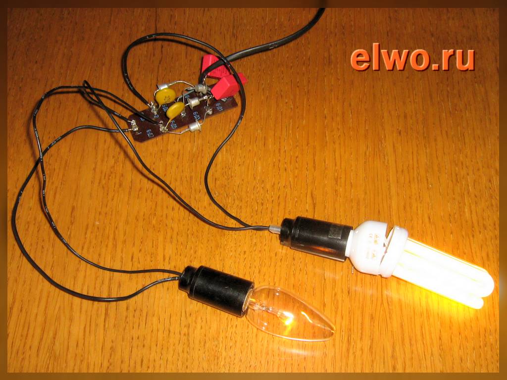
In the autumn I set the order in the garage and found three old burnt down fluorescent lamps. Marking - FL18S / D ( fig.1), the length of about 60 cm, diameter 26 mm. In one already the phosphor began to crumble inside the tube, and two externally still whole. I decided to remember my youth and make a lamp for a garage bench, lighting a lamp from a rectifier-doubler of mains voltage of 220 V.
This scheme was met in the magazines "Young Technician" and "Fisheries and Fisheries" in the section about aquariums - it was much easier to find a burnt out lamp and to solder four D7Z diodes with two MBM capacitors 0,1 mkF fig. 2) than to look for a choke, starter and a lamp with whole threads (there is a similar circuit and). As a ballast, assuming excess voltage after the ignition of a fluorescent lamp, an ordinary incandescent lamp was used. The brightness of the luminescent lamp depends on the resistance of its thread.
Fig. 2 
First, of course, you need to check the lamp for the possibility of working in such a scheme. The bridge from the diodes 1N4006 was soldered by mounting, the film capacitors of the MPR 0.1 μF 400 V were soldered to it and the rest of the commutation was dissolved. The incandescent lamp delivered a power of 40 watts. The first tube was lit up without problems ( fig. 3), the second externally the whole did not want to work, but the one that was rejected because of the phosphor shattering, also lit up, but only after replacing the 40-watt incandescent lamp with a 60-watt light bulb.
Fig. 3 
So, well, now it's behind the case. The luminaire planned to be put in the garage above the workbench, so the body needed strong and preferably so that it would cover the lamps from the top and front of the accidental impact - the garage, after all ...
Having rummaged in the scraps left from various construction repairs, I found a piece of metal profile of sufficient length and width-depth 49x39 mm (standard, probably, "50x40"). Approximately what you need, although it is a pity that it is narrow - it would be wide, it would be possible to fix both working lamps. However, no, I'm not sorry - there are only two nests for installing a fluorescent lamp only two ( fig. 4).
Fig. 4 
Approximately presenting where, what and how will be located inside the "profile", it turned out that its length is redundant and even if you install an additional cartridge for the incandescent lamp, a length of 1.05-1.1 meters is sufficient. I cut off the surplus, as well as saw out of the 16-mm-thick chipboard two rectangles 48х37 mm in size for installation in the ends of the box fig. 5 and fig. 6).
Fig. 5 
Fig. 6 
Then, the installation of all the nests and lamp holders for the corners from plastic (also remnants of repair) and fixing them "in place" with screws and nuts for 3 mm ( fig. 7)
Fig. 7 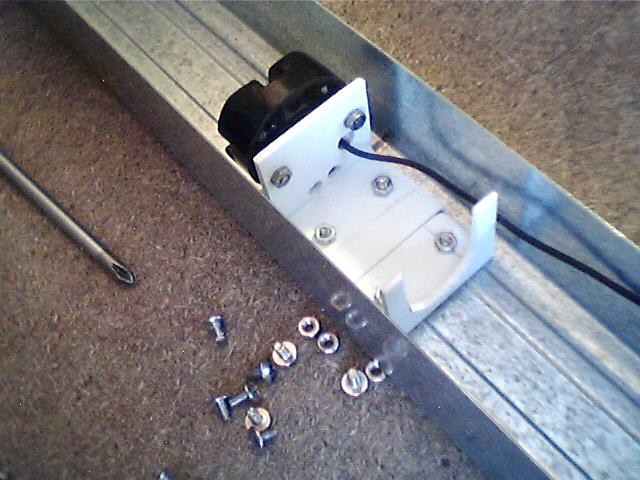
On fig. 8 You can see how it looks with the lamps, and on fig.9 It shows how the screws of the screws look from the back side of the "profile" - they hardly protrude and if necessary, a wooden block can be attached from above.
Fig. 8 
Fig.9 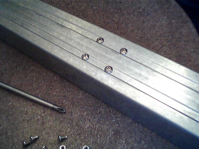
Diodes with capacitors are uncoated on a piece of unilateral foil-coated fiberglass with four sections of foil left on it ( fig.10). This "board" is fastened to the rear wall of the "profile" with the help of screw M3 ( fig. 11). On the front wall there is a power switch. The electrical wiring is made with insulated wire in additional fabric insulation - I do not know the name, the wire found, as you already guess, right there in the garage. The mains lead goes through the hole in the side insert near the switch - visible in the upper right corner on the figure 11.
Fig. 10 
Fig.11 
The electronic circuit of the luminaire does not need adjustment, but if it does not always immediately turn on after switching on, you can touch or hold your hand over the surface of the fluorescent lamp. If it seems that the incandescent lamp is too bright and still heats the case, you can try to replace it with a more powerful one - while it will shine more dimly ( fig. 12), and the luminescent is brighter, but in the latter, the service life will decrease (if, of course, we can talk about the "lifetime" of a lamp with a fused string).
Fig. 12 
The lamp LB-15 of 1984 of the release, found at home, was still tested, but she did not want to work under any conditions. But such experiment was conducted - the lamp with the FL18S / D lamp was connected to the 220 V network through the LATR and after its ignition the supply voltage was reduced to about 100 V. The incandescent lamp was much faded and the fluorescent lamp was almost unchanged-good enough property for use in the garage, where the voltage of 220 V is very unstable.
Andrey Goltsov, Iskitim
List of radio elements
| Notation | A type | Nominal | amount | Note | Score | My notebook |
|---|---|---|---|---|---|---|
| VD1-VD4 | Rectifying diode | 1N4006 | 4 | or 1N4007 |
We offer two variants of connecting fluorescent lamps, without the use of a throttle.
Option 1.
All fluorescent fixtures working from an alternating current network (except luminaires with high-frequency converters) emit a pulsating (with a frequency of 100 pulses per second) luminous flux. This acts tiringly on the sight of people, distorts the perception of rotating nodes in the mechanisms.
The proposed lamp is assembled according to the well-known scheme of power supply of a fluorescent lamp with a rectified current, which is distinguished by the introduction of a capacitor of high capacity K50-7 in it to smooth the pulsations.
When the common button (see diagram 1) is pressed, the 5V1 push-button that connects the light to the mains and the 5B2 button that closes the LD40 fluorescent lamp circuit with its contacts is triggered. When the keys are released, the 5B1 switch remains on, and the SB2 button opens its contacts, and the self-induction lamp emits from the resulting EMF self-induction lamp. When the button is pressed a second time, the switch SB1 opens its contacts and the lamp goes out.
The description of the switching device is not given because of its simplicity. For uniform wear of the lamp filaments, the polarity of its inclusion should be changed after approximately 6,000 hours of operation. The light flux emitted by the luminaire has practically no pulsations.
Scheme 1. Connections of a fluorescent lamp with a burnt thread (option 1.)
In such a luminaire, you can even use lamps with one burned thread. To do this, its terminals are closed on the pedestal by a spring of a thin steel string, and the lamp is inserted into the luminaire so that the "closed" legs receive a "plus" of the rectified voltage (upper thread in the diagram).
Instead of a KSO-12 condenser at 10,000 pF, 1000 V, a condenser from a failed starter for LDS can be used.
Option 2.
The main cause of failure of fluorescent lamps is the same as incandescent lamps - burning of the filament. For a standard luminaire, a fluorescent lamp with this kind of malfunction is, of course, unsuitable, and it has to be discarded. Meanwhile, according to other parameters, the life of a lamp with a burnt-up filament often remains far from being worked out.
One way to "resuscitate" fluorescent lamps is to use a cold (instantaneous) ignition. To do this, at least one of the cathodes must
to get by emission activity (see the scheme realizing the specified method).
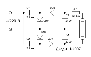
The device is a diode-capacitor multiplier with a multiplicity of 4 (see Scheme 2). The load is a chain of a series-connected gas discharge lamp and an incandescent lamp. Their power is the same (40 W), the rated supply voltages are also close in magnitude (103 and 127 V, respectively). Initially, when AC voltage is 220 V, the device works as a multiplier. As a result, a high voltage is applied to the lamp, which ensures "cold" ignition.

Scheme 2. Another option for connecting a fluorescent lamp with a burnt thread.
After the emergence of a stable glow discharge, the device switches to a full-wave rectifier mode, loaded with an active resistance. The effective voltage at the output of the bridge circuit is practically equal to the network voltage. It is distributed between the lamps E1.1 and E1.2. The incandescent lamp functions as a current-limiting resistor (ballast) and at the same time it is used as a lighting resistor, which increases the efficiency of the installation.
Note that the fluorescent lamp is in fact a kind of powerful zener diode, so that the changes in the magnitude of the supply voltage affect mainly the glow (brightness) of the incandescent lamp. Therefore, when the mains voltage is highly unstable, the lamp E1_2 needs to be taken with a power of 100 W to 220 V.
The joint application of two different types of light sources, mutually complementary, leads to an improvement in the lighting characteristics: the pulsations of the light flux decrease, the spectral composition of the radiation is closer to the natural one.
The device does not exclude the possibility of using as a ballast and a typical throttle. It is connected in series at the input of the diode bridge, for example, into a circuit break instead of a fuse. When replacing the D226 diodes with more powerful ones - the KD202 series or KD205 and KC402 units (KC405), the multiplier allows to feed 65 and 80 W fluorescent lamps.
Correctly assembled device does not require adjustment. In the case of fuzzy ignition of a glow discharge, or in the absence of a glow discharge at all, at the nominal mains voltage, the polarity of the connection of the fluorescent lamp should be changed. Preliminary it is necessary to take out burned-out lamps in order to identify the possibility of working in this luminaire.