Apparatus for adjusting the start began to appear long ago. Recently, the control gear has been heavily modified and improved. Not everyone understands how beneficial the installation of such devices.
Control gear for based on electronic components (electronic ballast) mounted in lighting devices. Fixtures with such a device significantly save electricity, and there is also no need to purchase new lamps, as the life of lamps is significantly increased.
Lamps with electronic ballasts shine with a pleasant quality light, which has a beneficial effect on a person, at least, does not harm him. The frequency of flicker of light of such lamps is about 400 Hz. At the same time, the eyes of a person are less tired, there is no headache.
Properties and views
Most often, control gear is divided into the following types:
- Single unit of equipment.
- Separate parts of the equipment.
Electronic ballasts can also be divided by type, given the type of lamp:
When considering the properties of the operation of such devices, they can be divided into:
Electronic.
Electromagnetic.
If we consider the ballasts for class matching according to the European classification, then the ballasts are divided into classes:
A 1 - adjustable.
A 2 - unregulated.
A 3 - with large losses (unregulated).
When buying a luminaire with a regulating starter, it is necessary to follow the latest developments and recommendations of specialists, as the devices are constantly updated, they introduce the latest modern innovations, which you may not know about.
Advantages
Innovative models of such apparatuses make it possible to turn on the lamp immediately after heating its electrodes. Also, when the lamp is operating, the ballast controls the optimum voltage value. Consequently, the power consumption is less when using such a device.
Electronic starters and adjustments are completely replaced by similar analogs. However, these are heavy and noisy chokes. They are practically not used in such devices. They will be described below.
The control gear has its own features and benefits:
- Reduces the flicker of the lamp.
- There is no strong flash of the lamp during the time of the starter fault, so the lamp life is increased.
- Provides lighting with a stable light flux.
- Starting electronic devices are equipped with power adjustment, which help to adjust the brightness of light in different rooms.
- Energy saving compared to conventional light sources.
- Safety from an environmental point of view, there is no need for special special disposal, since they do not contain mercury, other harmful and poisonous substances.
- Increased reliability, resistance to vibration, strength due to the fact that the design does not have a burner, filament, glass bulb.
- Does not respond to voltage surges.
- At the time of startup, it does not create an overload of the electrical network.
- Reduced current consumption, for conventional outdoor luminaires current is 0.5 amperes, compared to the light source on the discharge lamp - 2.2 amperes, and the starting current - 4.5 amperes.
- Saving money resources.
- Possibility of functioning of fixtures at low temperatures.
Operating principle
The work can be divided into the following stages:
The electrodes are heated. They start very quickly, within a few fractions of a second, a smooth light feed is created. This factor makes it possible to extend the life of the lamp before replacement. Also, fixtures equipped with such equipment can be switched on at low temperatures. This does not reduce their service life.
The second stage is ignition. This creates a pulse of high potential difference. This makes it possible to fill the flask with gas.
Burning is the final stage, maintaining a constant high voltage, which is necessary for the functioning of the lamp.
Scheme of control gear
Most often the circuit consists of a 2-voltage voltage converter. The structure is bridge and half-bridge. Bridge options are very rarely used.
First, the diode bridge rectifies the voltage, then it is smoothed out to a constant voltage. A half-bridge inverter makes the voltage high-frequency. The circuit uses a transformer with a core in the form of a torus with three coils. The main winding supplies a varying resonance voltage to the lamp. The rest work as additional windings, which in the opposite phase open the keys on the transistors.

As a result, before starting the lamp, the maximum current warms both filaments of the lamp, and the voltage on the tank turns on the lamp. It shines and does not change the frequency from the very beginning. The lamp start time is not more than one second.
Electronic ballasts with LEDs
Many lighting devices are used with a ballast. Let's consider, what advantages of application of electronic ballasts in modules of light-emitting diodes.
The main positive point here is the fact that the device is protected from strong voltage drops and electromagnetic interference. In other words, the control gear protects the LED module from the vagaries of the supply network behavior.
In addition, energy consumption is saved at around 30%, so this plays a big role in the application of electronic ballasts. Electricity is saved due to the fact that now it is not necessary to change the starters often, which very often fail, in contrast to the gear.
Models overview
The control gear is chosen by the majority of consumers. The most popular manufacturers of lighting devices with electronic ballasts are the following companies:
Helvar - the beginning of the production of products in 1921. From the very beginning the company has shown itself to be the most reliable in the production of radio engineering, has established the production of ballasts, the release continues to the present. Country of the manufacturer - Finland.
Tridonic is one of the leading companies in the production of lighting equipment. The firm in the late 70's began production of its products, which still glorifies the quality of Austrian goods.
Osram is a giant company in the field of manufacturing of lighting devices and component parts for them.
These eminent manufacturers produce non-expensive products, but this is justified by quality. Although, similar products of other firms can be purchased much cheaper.
Selection order
Before buying a ballast, you must first choose the right manufacturer. The most popular are the firms that we reviewed above. But, choosing a device from one of these companies, there is no guarantee that the selected device will not cause a malfunction of your light source, since in addition to the manufacturer, you need to pay attention to other points.
Particular attention should be paid to such parameters and properties:
Type of lamps used.
The power of the lamps.
Environmental conditions (specified in the device manual).
Electromagnetic ballasts
Simple electromagnetic ballasts (EMPAs) include conventional inductive resistance, consisting of a metal core on which a copper wire is wound. The use of this type of resistance causes a significant loss of power and heat release. The power of the 26-watt lamp operating on the network costs 32 watts for the network. This means that the power loss is 6 watts, this is 23%.
There are several methods of application:
- With a starter.
- Without a starter.
- With temperature limitation.
Principle of EMPRA
The scheme of an electromagnetic ballast with a starter is considered the cheapest and easiest.

When the power is turned on, the voltage along the winding of the throttle and the filament goes to the electrodes of the starter. It is made in the form of a small lamp with a gas discharge. The voltage forms a glow discharge, the inert gas begins to glow and heat its environment. The bimetallic sensor activates the contacts and a closed loop is formed in the circuit, by means of which the thread is heated. Thermionic emission is created. At the same time, the mercury vapor located in the flask is heated.
The voltage on the starter electrodes and discharge decreases, the temperature decreases. The bimetallic plate opens the circuit between the electrodes and the current stops. A self-inductance emf is formed in the throttle, creating a short-time discharge between the filaments.
The discharge can reach several thousand volts, which break through an inert gas with mercury vapor, an arc arises, which is the source of light.
The starter does not participate in the further work. After starting the lamp, the current needs to be limited, otherwise the circuit elements will burn out. This task is carried out by a throttle, the inductive resistance of which limits the increase in current, does not allow the lamp to fail.
Advantages of using EMPA with light source
- Uniform and fast start-up.
- No flickering.
- Increase the lamp life.
- Increased efficiency.
- Improved protection against electric shock.
- The power factor is above 0.9.
- The main advantage is a low price.
Disadvantages of EMPRA
- Large size and weight.
- Significant power losses, especially for fluorescent lamps.
- The frequency of the light stream is 100 hertz, this affects through the subconscious mind per person. The pulses of light form the effect of a strobe, when parts and objects moving with a frequency that coincides with the pulsation of light appear to the person to be immobile. This can adversely affect the increase in injuries in the workplace.
- Light is not controlled, it creates a limitation in comfortable conditions.
- The chokes emit a buzz, an unpleasant sound for a man.
To eliminate these drawbacks, for fluorescent lamps, the most effective way was to connect the lamps to the current of high frequency. To create such a connection, in series with the lamp, ballast is included in the form of an electronic device that converts the voltage of one frequency into another, and ensures the start-up of lamps. These devices are called electronic ballasts (electronic ballast), which we have already considered above.
TO Category:
Crane operators and slingers
Ballasts, control and protection devices
What devices and apparatus are referred to: ballasts and control devices?
Control gears and control devices include: circuit breakers, batch switches, magnetic starters, ballasts, power controllers, magnetic controllers, controllers, contactors, electromagnetic time relays, etc., and to protection devices - automatic switches, overcurrent relay, thermal relay , fuses, protective panels, etc.
What are the switches for?
What are the switches for?
Knife switches serve for closing and opening of DC and AC electric circuits with voltage not exceeding 500 V.
What are the switches?
In terms of the number of movable and fixed contacts, the switches are two- and three-pole, and by the arrangement of the handle, which serves to turn off and switch on the switch, -with a central handle, with a side handle, with a central lever drive and with a lateral lever drive. By the location of the clamps for connecting the wires, the switches are with the rear and with the front connection. What parts is the switch?
The switch consists of a panel, fixed contacts (jaws), movable contacts (knives) and a drive (handle or leverage system). The breaker is installed in a protective metal casing.
Packet switches of type ПВ-1-10, ПВ-3-10, ПП-2-10 / НЗ, etc.
What are the packet switches for?
Batch switches are used to turn on and off power and lighting electrical circuits of low power and voltage no more than 380 V.
What parts does the packet switch consist of?
The batch switch consists of a contact system and a switching mechanism.
Contact system is recruited from separate sections. Each section consists of an insulator, in the grooves of which are fixed contacts with screws for connecting the mains wires, and spring-loaded movable contacts with fibrous spark-out washers.
Fig. 1. Three-phase switch (a), starting box (b):
1 - movable contacts; 2 - electric wires from the network; 3 - upper fixed contacts; 4 - lower fixed contacts; 5 - moving contact pins; S - three cores of cable КРПТ; 7-panel; в - the handle; 9 - housing; 10 - grounding bolt

Fig. 2, Batch switch:
1 - a coupling bolt; 2 - contact plates; 3 - central swivel; 4 - contacts; 5 - plates
Separate sections are assembled on brackets with tightening bolts. The switching mechanism consists of a spring, a roller with a handle and a spring washer.
The lid has four locking protrusions, one to the other at an angle of 90 °, which determines the number of switching positions equal to four. This allows you to rotate the handle and the entire mobile system of the device in both directions with a switching frequency of no more than 300 per hour.
Starters magnetic series ПМЕ-200
Why are magnetic starters of the PME-200 series intended?
The magnetic starters of the PME-200 series are designed for remote control of asynchronous motors with a squirrel-cage rotor of 500 V with working currents not exceeding the rated operating current of the main contacts of the starter.
The PME-200 series starters with built-in thermal relays also protect the motors from overloads of unacceptable duration.
What do the letters and digits of PME-200 mean?
P - starter, M - magnetic, E - of a single all-union design. The number 2 indicates that the magnetic starter is of the second magnitude.
What parts are the magnetic starters of the PME-200 series?
Magnetic starters of the PME-200 series consist of contactors, thermal relays and shells.
Fig. 3. Schematic diagram of the magnetic non-reversing AC-starter:
1 - the coil; 2 and 4 - contacts; 3 - contact block; 5 - relay
The main part of all starters is a three-pole electromagnetic contactor, all contacts of which are bridged type with contact plates of silver-containing material. The starters of the PME-200 series can be reversible and irreversible. Reversing starters have two contactors with an electrical connection, which provides electrical lock through the open contacts of both contactors, which excludes the possibility of switching one contactor when the other is on.
Magnetic starter series PAE
What is the purpose of the magnetic starter series PAE?
Magnetic starters-PAE series (TU-16.536 489-75) are designed for remote control of three-phase electric motors with short-circuited rotor power from 17 to 75 kW at a rated voltage of 380 V AC at a frequency of 50 Hz.
In the presence of thermal relays, the starters also protect the controlled motors from overloads of unacceptable duration.
What parts are made of magnetic starter series PAE?
The magnetic starters of the PAE series consist of a contactor, a thermal relay (in the version with thermal relays), control buttons (in the version with control buttons) and shells (in closed version). The contactors have a simple kinematic scheme of rotary type, the movable part of which is a lever carrying an anchor on the long arm, and on the short one - a contact group.
The ratio of the arms is 2.4: 1, due to which the vibration time of the main contacts is no more than 2 ms.
The magnetic system consists of an anchor and a core. The anchor of the magnetic system is attached to the traverse, and the core is mounted on spring shock absorbers fixed to the contactor base and softening the impacts during the switch-on. The main contacts of the starters, consisting of fixed and movable bridged contacts, are closed by an arc chute chamber, in which brackets are mounted for more intensive extinguishing of the electric arc.
How does the magnetic starter turn on?
The magnetic starter is switched on as follows: when pressing the "Start" button button, the electric current enters the coil of the electromagnet (magnetic system), so that a magnetic field appears that attracts the armature of the electromagnet to the core. And since the movable contacts are connected to the armature of the electromagnet, the otiri 'will also rise and connect to the fixed contacts. At the same time, block-contacts are closed. When the "Start" button is released, the current to the solenoid coil will not come through the "Start" button, but through the block contacts and the "Stop" button, since this button is always closed, and the "Start" button is closed only when you press it .
If you want to stop the motor, press the "Stop" button. In this case, the supply circuit of the coil of the electromagnet will open and no current will flow into the coil, as a result of which the magnetic field disappears, and the anchor will move away from the core under the action of its weight; thus it will pull along and mobile main contacts, as a result of which the contacts will open and the current supply to the motor will stop.
What should the maintenance personnel follow when operating magnetic starters?
When operating magnetic starters, it is necessary to monitor the frequency and degree of wear of their contacts. If contact with carbon deposits occurs on them, clean the contacts with a cloth moistened with gasoline or with the shallowest sanding pad. It is impossible to clean the contacts of the starter with a file, since it is possible to remove a special metal deposited on the contacts.
What advantages does a magnetic starter have over a switch?
Magnetic starter in comparison with the switch has the following advantages:
the magnetic starter can be controlled remotely, i.e. at a distance, using the control buttons; - when the voltage in the network drops below the permissible level, the magnetic starter automatically turns off the current power circuit, because at low voltage the starter coil can not hold the magnetic system and the main contacts open;
in the presence of a thermal relay, the magnetic starter protects the motor from overloading, because the heating element of the relay is connected to the motor current circuit, and when the motor is overloaded, the heating element quickly heats up and a nearby bimetallic plate warms up next to it, which bends and releases the lever. The lever under the action of a spring pulls the rod, which opens the contacts that are in the coil circuit by magnetic starters, the motor is switched off. After a while, the bimetallic plate will cool down, and the thermal relay of the magnetic starter can be returned to the active state after pressing a special button. Heating elements of the thermal relay can be either interchangeable (designed for different currents), or adjustable (adjustment is made by changing the bending of the bimetallic plate).
Control buttons
What are the control buttons for?
The control buttons are used for remote closing and opening of the contactor coil circuits and magnetic starters with voltage not more than 500 V. The push-button control station usually has two buttons - one for starting the engine with the word "Start" and the other for stopping with the word "Stop". The "Start" button is normally open, that is, it is always open and closes the electrical circuit only when it is pressed. The "Stop" button, on the contrary, is always closed and opens the electric circuit only when it is pressed on it, therefore it is called normally closed (closed).
Contactors
What are the power contactors for?
Power electric contactors are designed for switching on and off the power circuits of electric motors and other devices.
What parts does the three-pole AC power contactor consist of?
The three-pole AC power contactor (Figure 53) consists of a panel, an electromagnetic system, a roller, power movable and fixed contacts, interlocking and opening contacts and spark-out chambers.
Fig. 4. The contactor of an alternating current: 1 - the coil; 2 - short-circuited coil; 3 - Anchor; 4 - power movable contacts; 5 - flexible conductor; c - roller; 7 - traverse; 8 - plates; 9 - break contacts; 10 - NO contacts; 11 - spark-extinguishing chamber; 12 - cheek spark-out chamber; 13 - power fixed contacts; 14 - magnetic system
The magnetic system, in turn, consists of a coil, a fixed core and an armature.
How does the three-pole AC power contactor turn on?
The three-pole power electric contactor of alternating current is switched on as follows: when the coil is turned on in the alternating current circuit, the magnetic flux generated by it attracts the armature and turns the roller on which the power movable contacts are strengthened. As a result, there is a short circuit of the power movable contacts and the power stationary contacts of the contactor. In addition to the power contacts, the contactor has locking and closing contacts. These contacts are closed and opened by the plates, which are fixed on the traverse, which is fixed on the platen. When the roller is turned, the contacts close and the contacts open.
After disconnection of the contactor coil, the armature returns to its initial position under the action of gravity of the moving system and the contacts open.
Controllers
What are the controllers for?
Controllers on load-lifting cranes with electric, drive are designed to turn on and off the electric motors of the crane mechanisms, to change the frequency and direction of rotation of the motors.
Controllers for controlling the electric motors of crane mechanisms are divided into two types according to the principle of operation:
direct controllers, or power, directly closing or breaking the power circuits of the motor by means of the contact devices of the controller with a manual drive;
remote control, or magnetic, in which contactors are used as an element switching the silo circuits of the motor.
The magnetic controllers are controlled by controllers switching the circuit of the contactor coils.
What parts does the power cam type controller consist of?
The power controller of the cam type consists of a housing, contact elements closed by spark arresters, and a cam shaft which is rotated by means of a handle mounted on the shaft end from the outside of the housing. The cams are mounted on a shaft covered with insulating material. On the lateral surfaces of the cams rollers are rolled, the deviation of which from their axis depends on which part of the cam is currently touching. When the projection of the cam rests against the roller, the lever with the movable contact deflects and opens the chain. If the roller is located in the cavity of the cam, the lever with the contact under the action of the driving spring is pressed against the stationary contact and closes the chain.
Which cam controllers are installed on electric powered cranes?
On the cranes with electric drive are installed cam controllers of type KKT, which have a two-link construction, due to which each washer is connected with two rollers of contact elements.
Technical characteristics of power cam controllers of KKT-A type
What parts does the magnetic controller consist of?
The magnetic controller consists of a group of contactors, relays and a number of other apparatuses mounted on a common metal frame and protected from atmospheric influences by a cabinet.
The main nodes of the magnetic controller are contactors, which are actuated by the controller.
Magnetic controllers, depending on the purpose and power of the controlled motors, have different designs, differing in the size of the contactors, the voltage of the main circuit and the control circuit, and also the electrical circuit. To control the electric motors of cranes in the drive of which a DC braking machine is used, compact magnetic controllers of the KBK-1 type are used, consisting of three magnetic controllers located in three separate cabinets. To control the motors in which the AC braking machine is used, standard magnetic controllers of the KBK-2u1 type are usually used, which also consist of three controllers (6TD.363.044.04, 6TD.363.066.04, 6TD.363.046.06).
In addition to these controllers on the cranes are used complete devices KBK-5uZ, etc.
Command controllers series KPP LLC
What are the controllers of the KP-1000 series used for?
Command-and-controllers of the KP-1000 series serve to control the devices of magnetic controllers of crane actuators. They consist of a body, a cover, one or two contact elements, a cam drum with cam plates and a locking mechanism consisting of a ratchet, two levers, a spring and a handle (Figure 54). The nominal voltage of these controllers is up to 500 V. The permissible continuous current is 10 A. The permissible switching current is 50 A.
What devices use a time relay?
Time relays are used in magnetic controllers for automatic closing and opening of control circuits with a given time delay.
Starting Resistance
What is the purpose of the starting resistances?
Starting resistors are used to ensure smooth start-up, speed control and braking of a motor with a phase rotor.
From what material are the starting resistances manufactured?
Starting resistances are made of cast iron (from cast elements) and high-resistance wire or tape (from constantan, nickel and fehrel); To prevent rust and to ensure a good contact, the cast iron elements are galvanized.
What are the main parts of the cast iron starting resistance?
Cast-iron starting resistances consist of an open box, the sides of which are connected by isolated rollers, on which are mounted cast-iron elements of resistance. Between these elements, insulating washers are laid. The conclusions for connecting working wires are made by special contacts, fixed between the elements.
In what electrical circuit do the starting resistors start?
Starting resistors are included in the electric circuit of the rotor of the three-phase motor through the brushes lying on the rings of the rotor shaft, and special contacts of the controller.

Fig. 5. Command controller;
1 - housing; 2) a cam-shaped drum; 3-arm; 4 - cover; 5 and b - fixing mechanism; 7 - blocks of contact elements; 8 - contact bridge; 9 - the lever; 10 - the lever spring; 11 - a bolt contact; 12 - bridge spring; 13 - rake; 14 - plate; A is the size by which the contact failure is controlled
The reduction or increase in the resistance in the motor rotor circuit during operation is effected by means of a controller. At the first position of the controller, the resistance is turned on fully, at the second - about 2/3, at the third - 1/2, at the fourth - 1/3; at the fifth position of the controller, the resistance is completely turned off, and the motor rotor is short-circuited as it were.
The crane operator should know that the resistance is calculated only for short-time modes of starting and braking the engines. Therefore, it is not possible to work long at the first, second, third or fourth position of the controller, as the elements of resistance can overheat.
Fig. 6. Overcurrent relay:
!! - rocker arm; 2 - contact; 3 - scale; 4 - brass sleeve; 5 - magnetic coil; 6 - the core; 7 - adjusting screw
To avoid disturbance of insulation between individual spirals or elements, atmospheric precipitation should not be allowed to resist. Therefore, the boxes with the elements must be suspended under the cabs or installed in the engine room.
Overcurrent relay
What is the purpose of the overcurrent relay?
The overcurrent relay serves to instantly disconnect the electric motor of the crane from the mains with an unacceptable overload or short circuit. Protection of electric motors and wires from ignition during overloads and short circuits, which is carried out with the help of the overcurrent relay, is called the maximum protection.
What parts does the overcurrent relay consist of?
The overcurrent relay consists of two coils with normally closed contacts that are connected to the motor and line contactor circuits. Inside each coil, an iron core with a weight is placed in the center, placed in a tube with a slotted slot. At the bottom of the weights * there is an adjusting screw, with which the weight, and with it the core can be moved along the tube. On the side of the tube there is a ruler with divisions showing the current strength to which the relay is adjusted. By turning the adjusting screw, the weights are set against the division, which indicates the current strength required for the given motor or network.
How does the overcurrent relay shut off the motor power circuit or the mains supply circuit?
The overcurrent relay shuts off the motor's power circuit or the circuit of the entire network as follows: when the overcurrent relay passes over the permissible value, the magnetic flux around the coil will increase, the core will rise, strike its pawl or latch and open the coil circuit of the line contactor, the line contactor will shut down. What is the purpose of thermal relays?
Thermal relays built into magnetic starters are designed to protect the motors from small but long-lasting overloads.
What devices use a voltage relay?
The voltage relay is used in magnetic controllers, where with its help the maximum and zero protection of the crane motor motors is carried out.
Automatic switches
What are the circuit breakers for?
Automatic circuit breakers are designed to automatically disconnect electrical circuits in case of violation of normal operating conditions (overload or short circuit currents).
What parts does the circuit breaker consist of?
The circuit breaker consists of a plastic casing, a cover, a base, movable and fixed contacts, arcing chambers, a switching device, a control mechanism and an overcurrent distributor.
How are they divided according to the principle of the operation of the overcurrent release?
According to the principle of operation, the overcurrent releases are divided into thermal, electromagnetic and combined. Moreover, the main element of the thermal release is a bimetallic plate, which, heated by the current of the overload passing through it, bends, while the free right end moves downward and, overcoming the force of the spring, turns the levers, so that the machine switches off.
What parts does the control mechanism of the circuit breaker consist of?
The control mechanism of the circuit breaker consists of a drive handle, a lever system and operating and auxiliary springs. And in the included position, the handle occupies the extreme upper position, and in the switched-off position the extreme lower position.
Protection panel
What is the protective panel for?
The protective panel serves to turn on and off the power supply to all mechanisms and devices of the crane, for the end and zero protection of mechanisms and the blocking of electrical equipment, as well as for maximum current and zero motor protection.
In which cases is a protective panel installed on the cranes?
The protective panel on cranes is installed in cases when the control of the motors of the mechanism is carried out with the help of controllers. The panels are usually designed for 220 and 380 V.
On some cranes, there are protective panels of type PZKB-160 and PZKB-400, designed to connect six electric motors.
Fuses
What are fuses for?
Fuses are designed to protect the electrical networks and electrical equipment of the crane from large overcurrent currents and short-circuit currents. The principle of their action is based on the melting of fuse-links with a sharp increase in the current in the circuit.
When electric current passes through the wires, heat is generated in them and the wires are heated. With a large overload, the wires can heat up so much that the insulation covering them can ignite.
In order to avoid such cases, fuses with a melting conductor (with a fuse-link) are included in the wiring. Fuse-links of fuses are made of lead, its alloys, zinc, aluminum, copper and silver. Fusible inserts are calculated in such a way that they melt before the temperature of the wires themselves reaches a value that is dangerous for their insulation.
Why is it forbidden to replace the calibrated fuse-links with copper or other wires in the fuses?
Because copper or other twists do not melt in a short circuit or overload, and such a fuse can cause a fire or electrical failure.
What fuses does the industry produce?
The industry produces the following fuses: fuses with closed collapsible cartridges without filler of the PR-2 series without latching mechanisms GOST 3041-45 for rated voltage up to 220 V (overall I) and up to 500 V (overall size II) for the rated current of the cartridge 15, 60, 100 , 200, 350, 600 and 1000 A. The fuse set includes: a cartridge, two contact racks for front and rear wire connection and one or two fuse links (depending on the current value).
Fuses NPN-20-60 are produced for rated current of 10, 15, 20, 25, 30, 40, 50 and 60 A, threaded fuses of the PRS-type series PRS-6 - 6 A, PRS-20 - 20 A, single-pole threaded safety locks GOST 1138-63 of type Ц27ПК-2 - on 6,10, 15 and 20 А.
TO Category: - Crane operators and slingers
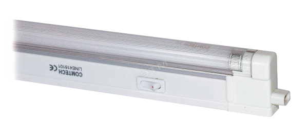
Tubular fluorescent lamps for many years regularly serve in different purposes. They are installed on the ceiling or on the walls, where they blend perfectly with the interior, plus perfectly illuminate the space. If we talk about the types of fluorescent lamps, about their power, then the variety of these light sources is huge. And this is one of the reasons why these lamps are popular among consumers. True, it should be noted that these fixtures had a fairly serious number of shortcomings, which consumers could not fight. The thing is that the fluorescent lamps can not be connected directly as the other types of luminaires. For them, special conditions are necessary for the supply of voltage, plus all it takes to control the current. This is what the ballasts for fluorescent lamps are engaged in, and the ballast is shorter.
Old gears are a set of several elements:
- starters for fluorescent lamps used for starting the light source itself and representing a bimetallic contact;
- a throttle for fluorescent lamps, by means of which the ripple of current is smoothed;
- a capacitor that functions as a voltage regulator.
So, all this set when the lamp was working tended to heat up (and strongly enough), while producing unpleasant noises for the ear. The service life of the instruments was low, which often led to the deterioration of the entire lamp in general, not to mention themselves.
How to eliminate shortcomings
All these negative aspects of the device were overcome when an electronic modification of the ballast equipment appeared on the light, but shorter than the electronic ballast. If you look at this block from a purely constructive side, then this is a block placed on one board.
- Firstly, this electronic ballast is small in size, and therefore it does not take much space in the fluorescent lamp itself.
- Secondly, you can easily install it yourself, without causing an electrician. This is in case the unit does not work for some reason and needs to be replaced. Although this happens rarely, the electronic ballast is a very reliable device. In addition, the connection scheme of the unit itself to the lamp is simple and does not require any special knowledge.
Many residents ask questions about replacing the old ballast with a new ballast. That is, can you make such a replacement? No problem, you just need to dismantle the starter, throttle and capacitor and install the electronic starter, securing it inside the luminaire. Connection diagrams for electronic ballasts are attached, as mentioned above, they are simple, so that any person who at least once screwed a light bulb into the cartridge, they will figure it out.
Advantages of fluorescent lamps with electronic ballast (2)
- The luminaire with a fluorescent lamp inside, in which the electronic ballast is installed, is switched on smoothly and, most importantly, quickly.
- The luminaire does not rustle or pulse (does not blink).
- The electronic ballast is practically not heated, and, therefore, some of the electricity does not go to its heating, which leads to the saving of electricity. This figure is 22%.
- In the electronic unit there are several types of protection for the fluorescent lamp itself. And this is a guarantee of increasing its service life, plus an increase in such a criterion as fire safety.
- And the undisputed advantage of this type of luminaires, where electronic ballasts for fluorescent lamps are installed, is an increase in human performance. With old lamps, their eyes quickly got tired of their constant flicker, the noise gradually got on its nerves, did not allow it to concentrate.
- Luminous efficiency of not less than 0.95, an excellent indicator. At the same time, the power consumption is reduced compared to conventional fluorescent lamps with the same light flux. Specialists have calculated that this saving will cover the cost of the electronic unit in eighteen months.
