Other things being equal, the proportional-integral-differential or PID (Proportional-Integral-Derivative) regulators allow you to raise the control accuracy 5-100 times compared to the positioner.
The most frequently used in the tasks of ACS TP are two-point control and PID control.
Two-position control enables the actuator (for example, a heater) to be switched on or off, depending on whether the measured parameter is below or above a given level. With on-off regulation, the system always has oscillations of the technological parameter, and the swing of these oscillations is determined only by the parameters of the system (the inertia of the sensors, the actuator and the system itself) and is practically independent of the regulator.
With PID control, the control signal depends on the difference between the measured parameter and the set value, from the integral, from the difference and the rate of change of the parameters. As a result, the PID controller provides the state of the actuator (intermediate between on or off), at which the measured parameter is equal to the preset one. Since the state of the actuator stabilizes, the accuracy of maintaining the parameter in the system rises tenfold. Thus, the law of regulation ensures accuracy.
In principle, the accuracy of the maintenance will be determined by the accuracy of the signal measurement and the intensity of external influences on the object.
Pb - initial temperature in the system
ti is the integration time constant
td is the time constant of differentiation
The control signal for the PID controller is determined by three components:

(Π is a proportional component)
The control signal that the controller generates is determined by how much the mismatch (proportional component), how long the error remains (the integral component) and, finally, how quickly the mismatch (the differential component) changes.
The quality of control that the PID controller provides depends to a large extent on how well the selected regulator parameters correspond to the properties of the system. This means that the PID controller must be set before starting work.
The quality of PID control is determined by the accuracy of its parameters. There are many different methods for tuning PID controllers. At the heart of most of them is the analysis of the transition characteristic.
Step 1. Setting the proportional component of the PID controller
Before the proportional band is adjusted, the integral and differential components are switched off, or the integration constant is set as high as possible, and the differentiation constant is the minimum possible. The required SP setting is set. The proportional band is set to 0 (the minimum possible). In this case, the controller performs the functions of a two-position controller. The transient response is recorded.

Tnach - initial temperature in the system
Test - set temperature (setpoint)
Δ T - temperature swing
Δ t - period of temperature fluctuations
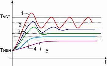
Set the proportional band equal to the range of temperature fluctuations: Pb = ΔT. This value serves as the first approximation for the proportional band. You should analyze the transient response again and, if necessary, adjust the value of the proportional band. Possible variants of the transient characteristics are shown in Fig.

Type 1 transition characteristic
The value of the proportional band is still very small, the transient response (and hence the adjustment of the regulator) is far from optimal. The proportional band should be significantly increased.
In the transient characteristic, damped oscillations (5-6 periods) are observed. If the differential component of the PID controller is assumed to be used in the future, the chosen value of the proportional band is optimal. For this case, the adjustment of the proportional band is considered complete.
If in the future the differential components will not be used, it is recommended to increase the proportional band so that the transient characteristics of type 3 or 4 are obtained.
In the transient response, a small ejection and rapidly damped oscillations (1-2 periods) are observed. This type of transient response provides good speed and quick output at a given temperature. In most cases, it can be considered optimal if the system allows for emissions (overheating) in the transition from one temperature to another.
Emissions are eliminated by an additional increase in the proportional band, so that a transient response of type 4 is obtained.
The temperature smoothly approaches the steady-state value without emissions and fluctuations. This type of transient response can also be considered optimal, but the speed of the regulator is somewhat reduced.
Type 5 transition characteristic
A strongly tightened approach to the established value indicates that the proportional band is excessively large. Dynamic and static control accuracy is small here.
Two circumstances should be noted. First, in all the cases considered above, the steady-state value of the temperature in the system does not coincide with the value of the set point. The larger the zone of proportionality, the greater the residual error. Secondly, the duration of the transient processes is the greater, the larger the zone of proportionality. Thus, one should strive to choose a zone of proportionality as little as possible. At the same time, the residual mismatch, characteristic for purely proportional regulators (P-regulators), is retracted by the integral component of the regulator.
Step 2. Setting the differential component (td) of the PID controller
This step is only present if a full-featured PID controller is used. If the differential component is not applied (using a proportional-integral (PI) regulator), then go straight to step 3 (Setting the integral component ti).
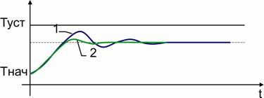
At the stage of setting the proportional band, a proportional band corresponding to the transient characteristic of type 2 is installed, in which damped oscillations are present (see Fig. 1, curve 2, Fig. 3, curve 1.). It is necessary to set the time constant of differentiation so that the transition characteristic has the form of curve 2 in Fig. As a first approximation, the time constant of differentiation is made equal to td = 0.2Δt.
It is noteworthy that the differential component eliminates damped oscillations and makes a transient response similar to type 3 (see Fig. 1). The proportional band is smaller than for type 3. This means that the dynamic and static control accuracy in the presence of a differential component (PD controller) can be higher than for a P controller.
Step 3. Setting the integral component (ti) of the PID controller
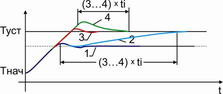
After adjusting the proportional component (and if necessary also the differential component), the transition characteristic shown in Figure 1, curve 1, is obtained. The integral component is designed to remove the residual error between the temperature set in the system and the setpoint. Start to set the integration time constant from the value equal to Δt.
Type 2 transition characteristic
It turns out at an excessively high value of the integration time constant. The output to the set point is very tight and lasts approximately (3 ... 4) ti.
Type 4 transition characteristic
It turns out that the integration time constant is too small. The output to the setpoint also lasts (3 ... 4) ti. If the integration time constant is decreased, then the system may experience oscillations.
Type 3 transition characteristic
Optimum.
The result
Thus, we examined the process of step-by-step adjustment of various components of the PID controller. At each stage, the type of the transient response was monitored and, if necessary, the values of the PID controller parameters were corrected. In this case, the initial values of the parameters were the parameters of the transition characteristic obtained for the on-off regulator, namely: Pb = ΔТ; ti = Δt; td = 0.2Δt. Experience shows that for the majority of cases, these parameter values provide PID control close to optimal, and further correction of the parameters is not required.
Regulator - A device that monitors the operation of the control object and generates control (regulating) signals for it.
Regulators can be implemented as a separate device or as an application package in the main program of the control device.
Hardware controllers can be divided:
1. on using external energy for work:
regulators of direct action, do not use external energy. Work at the expense of the energy developed by the sensor, simple in design, not expensive, but have not high accuracy. They are used in the simplest control systems.
regulators are not direct action, use external energy for their work is the main kind of regulators.
2. the type of external energy used:
- electric;
- pneumatic;
- hydraulic;
- combined.
3.Po kind of adjustable parameter: regulators of temperature, pressure, level, flow rate, etc.
4. According to the law of regulation, i.e. on the change of the regulating effect in time with the change of the regulated parameter (by the form of the transient characteristic of the regulator). These controls can be hardware type (analog) and digital, in the form of a software package.
There are the following types of regulation:
- P (P) means " proportional»
- I (I) is an "integral"
- D (D) - " differential»
- PI(PI) - " proportional and integral»
- PD(PD) - " proportional and differential»
- PID(FID) - " proportional, integral and differential»
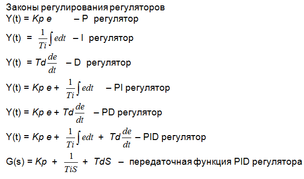
Properties and types of regulators
1. P-regulator, proportional regulator.
The transfer function of the P-controller is: Gp (s) = Kp. The controller produces a control action on the object in proportion to the magnitude of the error (the larger the error e, the greater the control action Y = Kp * e).
2. I-regulatorintegrating regulator.
The transfer function of the I-controller is: Gi (s) = 1 / Ti * s. The control action is proportional to the integral of the error e:
3.
D-regulator, a differentiating regulator.
Transmission functionD-regulator: G d(
s) =
T d *
s. D the regulator creates a control action only when the controlled variable is changed:Y=
T d *
de/
dt.

Have P-controller , it is also called static, the change in the position of PO is proportional to the deviation of the regulated parameter " e»From its set valueX 0.
Benefits P-regulator - its speed (short regulation timetp ) and high stability of the regulation process.
Lack of - the presence of a static error δ
X, i.e. after the end of the control process (during the regulation timet p) The parameter does not return exactly to the specified value, but differs from the set value by δ
X, which reduces the accuracy of regulation. With an increase in the gain Kp, the quantity δ
It's thin, but the ACP may lose its stability. At Kp = Kp Kp, the system produces non-damped oscillations with a constant amplitude, and for an even larger Kp, with an increasing amplitude. Fig. 93
1 –
regulated process withPregulator at K p<
K p
.кр
2 - Regulated process withK p = K р.кр
T cr - the period of non-damped oscillations atK p = K р.кр
t p - control time for a stable process
X 0 - initial value of the controlled parameter
δ X - static error
Have I-controller , it is also calleda static, the change in the position of PO is proportional to the integral of the deviation " e"Of the adjustable parameter from its set value X 0 . The regulator will move until the parameter reaches an exactly specified value, i.e. he does not have a static error δ X = 0. This is its dignity, but its disadvantage is its poor stability, long regulation time. It can be used on inertial objects with self-leveling.

Have D -Controller, the regulating effect is proportional to the rate of deviation of the parameter from the target, i.e. derivative of deviation« e». In Figure 94 with a step changeU (t), an error message occurs e, which will decrease in the process of regulationt , until the parameter reaches a new valueU (t) .t 0 - the beginning of the deviation of the parameter,t 1- the moment of operation of the regulator without a signal by the derivative, "Δ" - the zone of insensitivity of the regulator.
The speed of the deviation at the initial moment is large and therefore the speed signal will be large, The controller will immediately start acting at the moment t1 , even before the noticeable "Δ" deviation of the parameter and the parameter will be set faster to the task U (t).
Thus, this controller has an increased speed - this is its dignity.Lack of - is not stable in the work, the poet does not use it separately. But this principle is used to improve the quality of regulationPDand PIDregulators.
Combining protozoaP, I, D , regulators, receivePI, PD, PIDregulators. In practice, R, PI, PIDregulators
PI - regulator, combination RandIregulators. Has the merits of both. From R -good stability, fromIδ X = 0.
PD- regulator, combination Rand Dregulators.Has the merits of both. From R -good stability, fromD– High performance, but static error persistsδ X, as in Rregulator.
PID- regulator, combination P, I and Dregulators.Has advantagesthree. From R -good stability, fromI- no static errorδ X = 0, from D– increased speed.
PID- the controller is most versatile in its capabilities.At present, mainly electronic and digitalPID -Regulators, based onwhom various regulatory laws can be implemented.
Structural scheme PIDregulator
Figure 95 shows the structural diagramPID controller
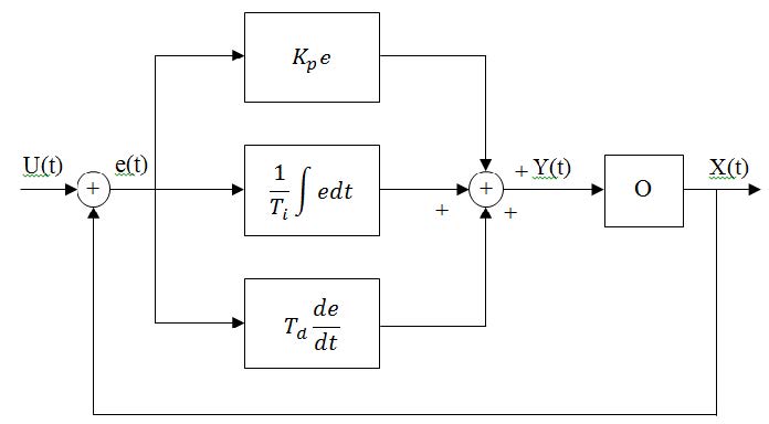
Fig. 95 Structural diagram of PID regulator
K p- regulator gain
T iIs the integration constant
T d- differentiation constant
These are the tuning parameters of the regulators
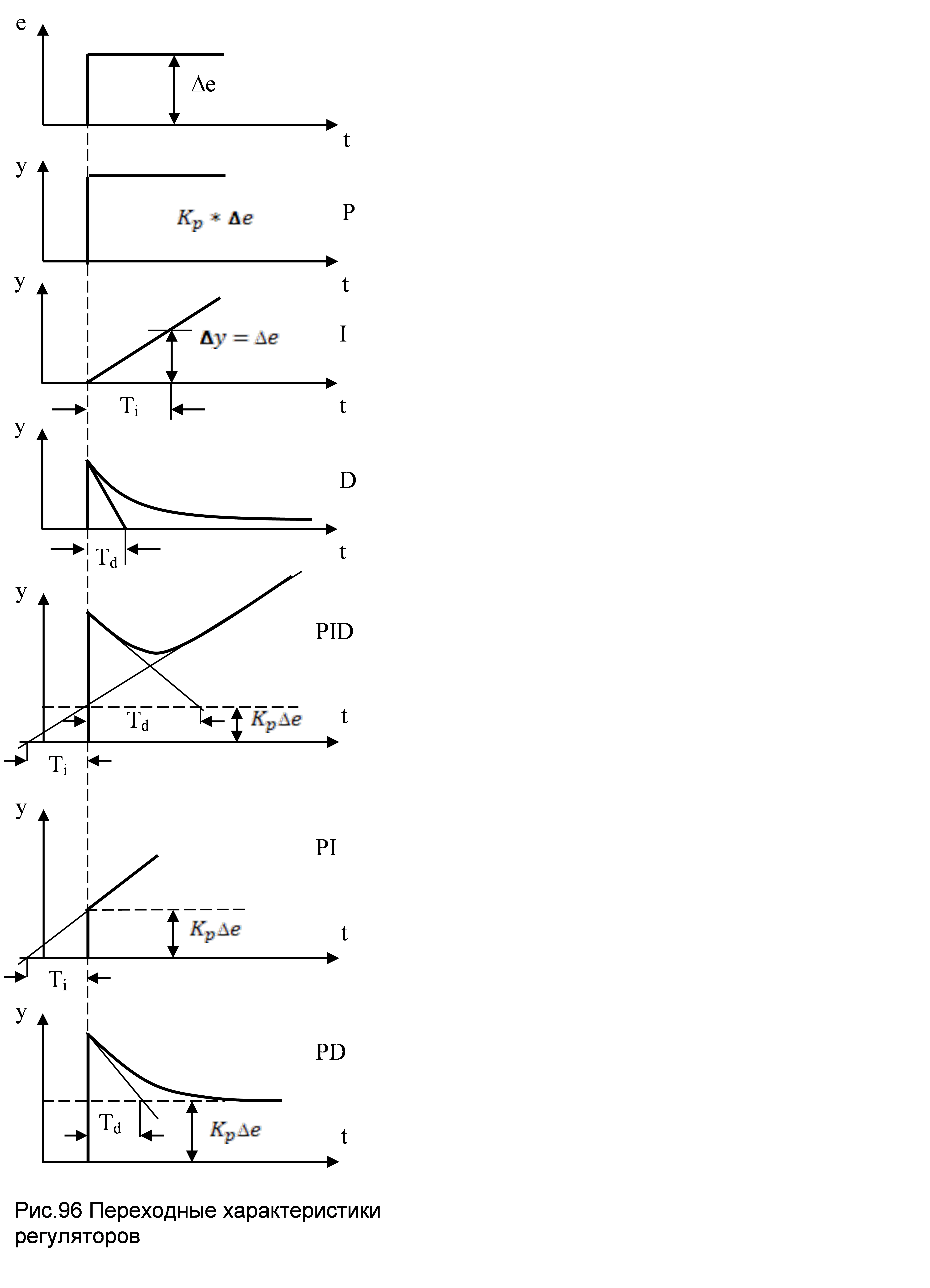
Transient characteristics of regulators are shown in Fig.96. ForP, Iand Dregulators they are similar to the characteristics of the corresponding typical links. For other regulators, the characteristics are obtained by adding characteristicsP, I, and D regulators.
Transient characteristics show how the regulating effect of the regulator changesY in time with deviation of the controlled parameter X from the job ie. when an error signal "e" appears.
If there is a deviation, a decrease in the temperature in the object(X) , y Rregulator, the control valve opens slightly(Y) proportional to the temperature deviation and will stop. The heat input will increase and the temperature, quickly recover, but not exactly, a static error will occur δ X.
Have PIDregulator, at the expense of R andD the valve will first open strongly, providing a quick supply of heat, but then, in order not to cause overheating, will begin to cover up, providing the necessary heat to the object. Then comes into effectI component, which opens the valve until the static error is removed δ X. This wayDthe component increases the speed of the regulator, and Ithe component removes the static error δ X.
Control questions
1. If y R regulator Kr increase, then how will it change δ X?
2. What gives Icomponent of the regulator?
3. What property?and how it affects Dcomponent of the regulator?
4. Which quality controller is the worst and the best.?
Electrical regulator circuits
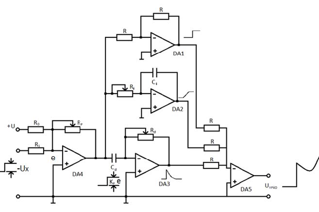
In Fig. 97 shows possible options for implementing regulators on operational amplifiers. R the regulator is implemented onDA1.
Gain R constituent Kr = Rp / R1. In the scheme, PID regulator on DA1 a follower R component because K =R / R = 1 , and the amplifier functions DA 4, which at the same time is a leveling deviceoe compares the signal from the master+ U with sensor signal -Ux. Their difference e = U- Ux enters the doorDA. Sign edepends on the direction of change of the parameter. Setting parameters forIparts of T i= RiFROMi, and for D parts of Td = RdCd. On DA5 An adder is implemented, which sums all the components, and on the output we get a signal varying byPIDlaw.
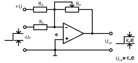
P regulator
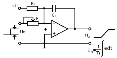
I regulator
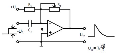
D regulator
PID controller
Fig. 97Electrical CircuitsP, I, D, and PID controllers
The law governing the electronic Ti,Td.

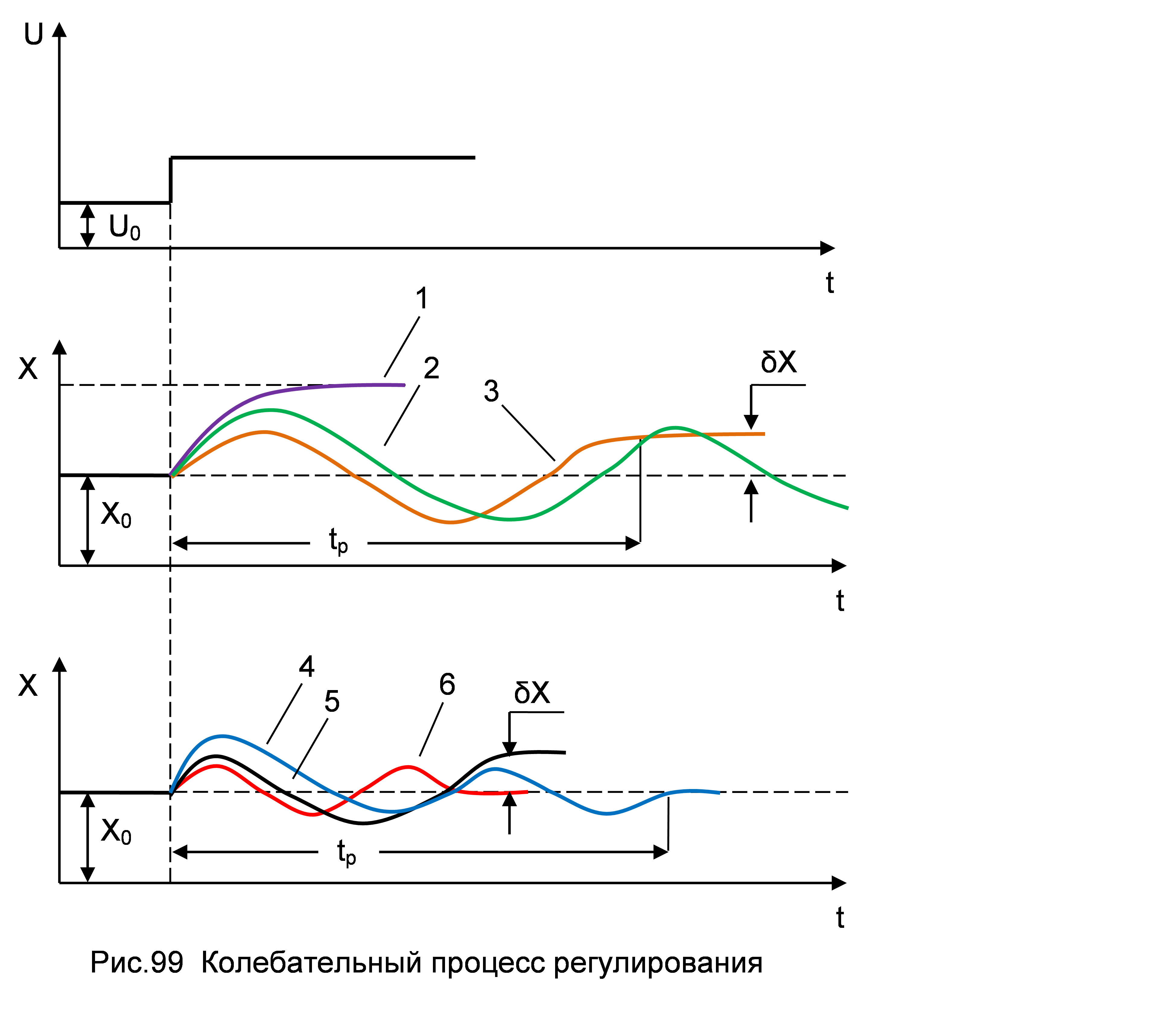
1 - without regulator
2 – Iregulator
3 – Pregulator
4 – PIregulator
5 – PDregulator
6 – PIDregulator
X 0 - initial value of the controlled parameter
δ X - static error
The PID controller is a process control device that is used in the PID control method based on three control laws: proportional, integral and differential.
The operating principle of the PID controller
Integral bellows and variable limits allow for integral regulation. Two differential bellows and other variable limits allow the controller to perform differential control.
If the output increases, the inlet bellows and the lower differential bellows expand. The upper differential bellows expands later due to variable constraints. The balancer turns, and the output immediately rises.
When the input signal flows completely into the upper differential bellows, this bellows will apply a force that will destroy the force applied by the lower differential bellows. At this point, the differential control stops. At the same time, when this happens, the feedback bellows expands as a result of a change in output. The change in output is applied to the integral bellows, which causes a force that tends to keep the valve closer to the nozzle. This action keeps the output at a high level for a time when the process variable is not equal to the setpoint. The output will continue to increase until the process variable returns to the setpoint value.
Where is the PID controller applied?
The PID controller will be a good choice for a gas-fired oil heating furnace, because the subsequent process where heated oil enters allows only very small deviations in the oil temperature from the set point, and large delays during heating make it very difficult to determine and eliminate deviations .

One of the reasons for the lag is capacity. The furnace has the ability to store a large amount of heat inside its walls. Accumulated heat is transferred to oil, but transmission does not occur instantaneously. If the internal walls are heated too much, it will take some time to lower their temperature, during which time oil can be overheated. If the internal walls are not sufficiently heated, then the oil may not get enough heat.
The differential component of the PID regulator helps to overcome delays by developing effective pre-emptive actions. The integral component continuously adjusts the output signal when there is an offset until the controlled temperature returns to the set point.