The inclusion of a quartz resonator in the oscillator circuit increases the stability of the generated frequency when exposed to destabilizing factors. For this reason, in modern transmitters, quartz oscillators are used as reference oscillators. Amplifying element in modern quartz oscillators is usually a transistor, due to its small dimensions and weight, low power consumption, high reliability and instant readiness to work.
Schemes of quartz oscillators are classified depending on the operating frequency (w K, w 0, w K ... w 0), the place of switching on the circuit and the nature of the resistance (inductive, minimum and active) of the quartz resonator. By the nature of the resistance of the resonator circuit of quartz oscillators are divided into two groups. The first group includes schemes in which the resonator performs the function of one of inductive resistance three-point scheme.
The second is the circuits in which the resonator is connected in series to the OC circuit. In this case, the generator is most easily excited at the frequency at which the resonator has the minimum active resistance, which corresponds to the deepest OS. It is practiced to include in the oscillatory circuit a resonator generator operating at a frequency of series resonance.
When constructing generators of the first group (oscillatory: generators), the inductive nature of the resonator resistance is used in the frequency range w K ... w 0 (Fig. 5.4), i.e. that the resonator is equivalent to a high-quality coil. Consequently, one of the inductances of the three-point oscillator circuit can be replaced by a resonator (see Fig. 4.8, a, b).
The resonator can be turned on between the base and collector of transistors in the autogenerator assembled according to the capacitive three-point scheme, also between the base and the emitter, collector and emitter in the autogenerator assembled according to the inductive three-point scheme. Practical use found the generators according to the three-point capacitive scheme. In such generators, the maximum frequency stability is realized, the generator circuit is simpler to adjust, more reliable than inductive three points. A schematic diagram of such a high frequency generator (without power supply circuits) is shown in fig. 5.5, a.
We note two points characteristic of the operation of the oscillator according to the scheme of fig. 5.5, a. First, a malfunction or shunting of the resonator, as well as an open circuit in its circuit, leads to a breakdown of the generated oscillations, which in itself is useful, since the generator operation without a quartz resonator is excluded. Secondly, a sufficiently large RF voltage is generated at the resonator, which causes its heating, which reduces the stability of the generated oscillations. For this reason, quartz oscillators perform as low as possible.
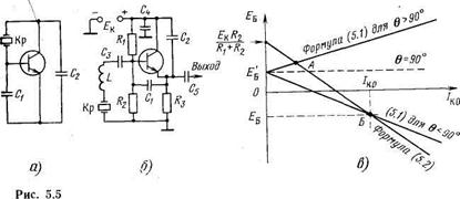
One of the possible practical circuits of a transistor quartz oscillator assembled according to the capacitive three-point scheme is shown in Fig. 5.5 b. The quartz generator is excited at a frequency close to the frequency of the series resonance w K. For frequency erection, a coil L is provided, connected in series with the resonator. The operating point of the transistor is determined by the resistances R1, R2 and R3. The capacitors C1 and C2 together with the resonator Kp and the coil L form a capacitive three-point circuit (Fig. 5.5, a). Capacitors C3 and C5 - separation.
When operating at frequencies above 15 ... 20 MHz, the resonator has a thickness of 0.1 ... 0.2 mm, which is difficult to implement and limits the maximum possible frequency. At higher frequencies, the resonators can operate on the harmonics of the mechanical oscillations of a quartz plate. It is known that a quartz plate with oscillations in thickness can oscillate on the harmonics of mechanical oscillations. You can
get a much higher generated frequency.

Consider the scheme of the simplest generator. For its self-excitation, it is necessary to balance the phases at a given frequency. The generator can be made according to the inductive or capacitive three-point scheme. Such schemes are called oscillatory. Currently, a three-point capacitive circuit is usually used as a cheaper option. Figure 1 shows a similar circuit made on a bipolar transistor.
Figure 1. Capacitive three-point, made on a bipolar transistor
In this scheme, the amplifying element VT1 is included in the circuit of the circuit L1 C2 C3, the resonant frequency of which determines the frequency of generation of the circuit. The depth of the feedback is determined by the ratio of the capacitances of this circuit and the gain of the transistor at a given self-excitation frequency.
Shown in Figure 1 schematic diagram The generator is quite complicated. This is determined by the number of elements of thermal stabilization (R1, R2 and R4) and the setting of the DC mode (resistor R3 and capacitor C1). The oscillations generated by such a generator are not quite suitable for synchronizing digital microcircuits, since a sinusoidal voltage is present at the output of the described generator. It needs to be converted to logic levels that perceive digital circuits.
The generator can be constructed on the basis of a single logical inverter. As mentioned in previous chapters, any one has an enhancement. This will ensure a balance of amplitudes. The balance of the phases will be provided in the same way as in the previous generator circuit. The circuit of a three-point capacitor, built on the basis of a logic inverter, is shown in Figure 2.
Figure 2. Capacitive three-point, made on a logical inverter
When implementing generators on logical elements, it is necessary to ensure that when starting the generator the logic element is in active mode. In normal power-up the logical inverter is in limiting mode. In the limiting mode, a hard generator startup mode is performed, therefore, for the occurrence of self-oscillations in such a scheme, it will be necessary to send a powerful impulse to the inverter input.
For the spontaneous occurrence of oscillations in the generator circuit, it is necessary to transfer the logic element to the amplifying mode. To do this, the inverter needs to be covered with negative DC feedback. In the diagram shown in Figure 2, this is accomplished by closing the input and output of the chip through the active resistance of inductance L1.
The signal at the output of the first inverter due to the filtering properties of the circuit will also be sinusoidal. The second inverter is used to convert the shape of the output voltage to a rectangular and bring the level of the generated signal to digital logic levels. In other words, it is used as a limiting amplifier. In addition, this inverter performs the functions of a decoupling (buffer) amplifier. This means that changing the load parameters will not affect the generated frequency.
It is known that the oscillation stability of the LC generator is low. Quartz oscillators are much more stable. The circuit on one inverter can be used to build quartz oscillators. In this case, in a capacitive three point instead of inductance should include a quartz resonator. A diagram of a quartz oscillator on one logical inverter is shown in Figure 3.
Figure 3. Scheme of a quartz oscillator, made on a logical inverter
The capacitances in the frequency chain are usually selected from 10 to 30 pF. The value of these capacitances is determined by the value of the quarter-holder capacity, which ranges from 3 to 5 pF.
The ratio of capacities sets the depth of feedback, which means the stability of the generator start-up in the temperature range. At high frequencies, capacitances are usually equal. In low-frequency generators, capacitance C1 is desirable to choose less than capacitance of capacitor C2. This will provide a higher voltage at the input of the inverter, which in turn will lead to less current consumption. If it is necessary to adjust the frequency of the generator, a tuning capacitor can be used as the capacitance C2.
Quartz resonator does not miss d.C.therefore, to ensure automatic start of the generator, it is necessary to use additional resistors. In the circuit in Figure 3, these are resistors R1 and R2. Resistor R1 puts the inverter into active mode. The ratio of resistors R1 / R2 determines the gain of the active element generators.
When using very high-frequency quartz resonators, resistor R2 to facilitate self-excitation of the generator may be absent. When working with low-frequency quartz resonators, the resistor R2 and the capacitance C2 provide the necessary phase shift and prevent the generator from self-excitation at the frequency of the crystal holder capacity. In addition, the resistor R2 limits the power dissipated on the quartz crystal, which allows the use of small-sized crystals in the generator.
Quite often it is necessary to stop the generator to save electricity consumption. In this case, instead of the logical inverter, you can use the scheme "2I-NOT."
Figure 4. Scheme of a quartz oscillator, made on the element of the logical "And"
A similar circuit is shown in Fig. 4. It is this circuit that is used inside most modern microcircuits as a master clock generator.
Literature:
Together with the article "Oscillatory generator circuits" read:
http: //sayt/digital/gen.php
Fig. 20. The design of the steering device model radio-controlled vessel
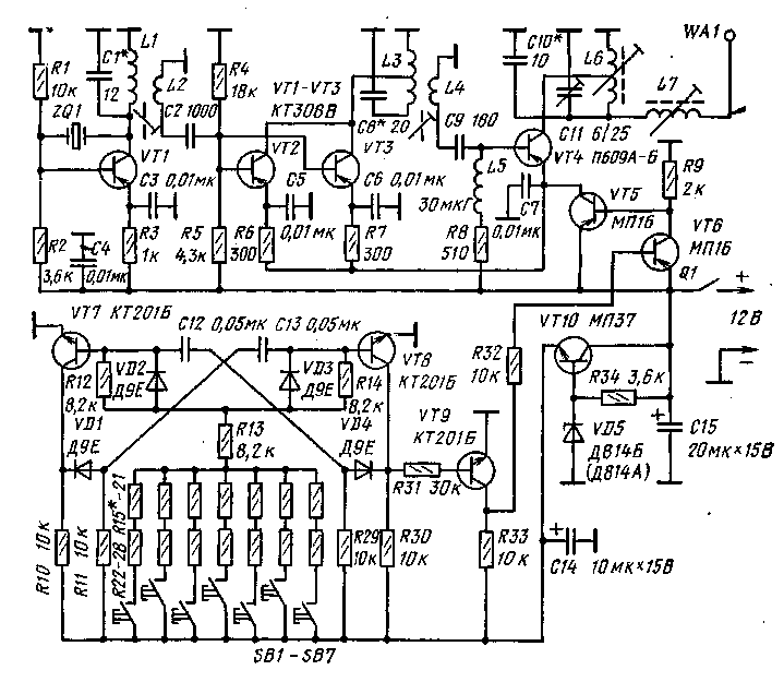
Many constructive solutions implemented in car models can also be successfully applied on radio-controlled ship models. In the ship-modeling sport there are several classes of radio-controlled models: speed, performing figure courses; models that hit with a nasal needle floating balls-models leading a sea battle; sailing yachts. Control of high-speed ship model with an engine internal combustion Similarly to driving a racing car. If on ship models they put two, ru-la, then their axes are tied together by a steering linkage. On models it is allowed to install active steering wheels, various nozzles and thrusters. An example of a model version of the active steering wheel is the helical steering wheel (Fig. 20) of the construction of shipbuilder I. Efremov from Almaty. With the help of this rudder, the model of the vessel is able to turn around 360 degrees in place (without moving). Both in front and in reverse, the ship's maneuverability is identical. Consider the device helical steering. A fixed feather 12 steering wheel with the help of legs 2 and screws 3 attached to the hull 1 of the vessel. The ring 14 is reinforced in the re, which has a three-bladed propeller 13 embedded. On the two covers of the ring are mounted the bearings 4 of the shaft 5. A bracket 6 is installed on the side of the right cover that serves as a support for the conical pair of gears 7, 8. They are fixed on the shafts 5 and 10. On the shafts for this provided ly-skiing. Propeller shaft 10 of the steering device is wound inside the hull of the vessel with the aid of the stern tube 9 and the bracket 11 attached to the hull. It is recommended to propel the propeller shaft in motion with a 15–30 W electric motor. The diameter of the tail rotor and the installation angle of the blades are selected empirically. For a model of a cargo-passenger vessel with a displacement of 12 kg, the screw should have a diameter of 30 mm; its four blades should be mounted at an angle of 45 ° to the axis. Such a screw is necessary for models competing in the passage of the figure course. On high-speed and other models, steering wheels with turning feathers and having a self-centering system when stopping the supply of a steering command work better. Often, radio-controlled models of various ships are designed for demonstration and experimental purposes. In these cases, various controlled mechanisms are installed on the model. To turn them on and off, a selector unit can be applied, the circuit of which is shown in Fig. 3. We will also give some tips that will be useful in the design and manufacture of aircraft models. Aircraft modellers at the initial stage of the development of radio control models of aircraft should focus on the Supranar-83 serial equipment and the Raduga engine with a cylinder capacity of 7 or 10 cm 8. Nevertheless, other engines are quite suitable for installation on an aircraft model. On models-copies of the I-3, I-6, “Coach-226”, ANT-25 airplanes with a pointed fuselage, it is possible to install the Raduga engine with a cylinder capacity of 7 cm 3. The Rainbow engine with a cylinder capacity of 10 cm 3 can lift into the air models weighing up to 5 kg. When using a glowing motor, it is necessary to seal the electronic equipment on board, and to cover the model with a thin layer of ED-6 epoxy resin. This is due to the fact that the exhaust gases containing unburned methanol dissolve the paint and insulation of radio equipment and the enamel coating of the model's skin. The mass of radio equipment of the model-copy of the aircraft should not exceed 40 - 45% of its total mass. The load on the carrier surface of the model during its flight at a wind speed of 5 - 7 m / s should be no more than 40 - 45 g / dm 2. The model is calculated so that the center of gravity after placing all the equipment coincides with the center of pressure of the wing. In the design and manufacture of the fuselage frame, you need to carefully consider the attachment points of the chassis, receiver, steering gears, power sources, fuel tank, etc.Fig. 21. The option of placing equipment on a radio-controlled model aircraft:
1 - power supply;2 - receiver;3 - steering cars control(D - often the rotation of the motor shaftRV - elevator,RP - steering wheel);4 - thrust; 5 - steering wheel;6 - steering wheel; 7 - elevator;8 - steering gear control aileron; 9 - ailerons;10 - connection cable; 11 - traction slide switch;12 - pivot arms;13 - front wheel rack;14 - bowden cable The most simple design models of aircraft I-3, I-6, Yak-12. They are good because they have a high wing, which provides increased stability of the model in flight. The fuselage of these aircraft has large flat surfaces. The absence of complex rounding and transitions simplifies copying. Models-copies of the ANT-25, Yak-18, “Coach-226” and others, which have a low wing, are usually built by modellers with great experience. The frequency of rotation of the engine shaft in flight is controlled by the simultaneous blocking of the inlet and outlet ports of the throttle valves. Throttle valves can be sector, plate, zolotnikovymi. Serial micromotors are not equipped with flaps, they are installed by the modellers themselves. - At pic. 21 shows the placement of radio control equipment on the aircraft model. The drawing is schematic in nature and gives only a general idea of the nature of the structure. The first made radio-controlled model of the aircraft must be training, it is built more durable and stable in flight, capable of withstanding gross landings and errors in piloting technology. Such training aircraft models combining speed in the flight capabilities of a multi-team model with ease of piloting and stability in flight are constructed by many leading masters of model aircraft sports. Here are the technical data of the training model designed by I. Nikiforov (Moscow Regional Technical Club of Sporting Iodineism): wingspan is 1880 mm; model length 1350 mm; bearing surface area 69 dm 2; wing area 55.1 dm 2; flight weight 2950 g; fy-zhelezha mass without engine 1150 g; percentage alignment SAH -thirty%; angle Havewing 6 °; the ratio of the diameter to the pitch of the model 260/140 screw; engine displacement 5 cm 3; The number of control commands is 8. In order to increase the reliability of radio equipment, the receiver and the power source are wrapped with foam rubber or sponge rubber before installation into the model. All mechanical rods, assemblies and fastener parts must be manufactured on high precision, without backlash. Successful piloting of the model should be preceded by regular trainings of the modeller according to the established program. It is necessary to work out a simulator in the management of a model when mastering individual elements of a flight, I only later, after identifying the flight capabilities of the model, proceed to working out aerobatics.3. QUARTZ GENERATOR- IMPORTANT RADIO OF RADIO CONTROL EQUIPMENT
Automatic entry into communication is a condition that modern equipment for radio control of models must satisfy. An indiscriminate radio communication is provided by a quartz stabilization of the frequency of the oscillators located in the master oscillator of the transmitter and in the local oscillator of the receiver. Radio amateurs often use random quartz resonators (quartz), designed for a variety of equipment and without a technical passport indicating the parameters of the resonators. In this connection, it is not always possible to make a full calculation of the oscillator with quartz frequency stabilization, but radio amateurs using the sample method in the process of setting up the equipment achieve the desired results. Knowing the principle of operation of the used auto-generator variant, it is much easier and more accurate to set the master oscillator or the local oscillator at the desired frequency. We will talk first about the usual auto-oscillator, and then about the most acceptable variants of auto-oscillators with quartz resonators. Let's start with the answer to the question: what is an autogenerator? The auto-generator is a power source energy to high-frequency oscillation energy converter that operates without constant external influence. The impetus for the excitation of the oscillator are short-term transition processes when the power source is turned on and the current fluctuations in the transistor circuit. If self-excitation conditions that occur in the oscillator circuit are satisfied, weak oscillations are amplified, which means that more energy is supplied to the oscillator circuit in each subsequent oscillation period than is lost in it. The amplitude from cycle to cycle increases, but not infinitely, since the auto-generator is a non-linear system. After several cycles, the increase in the amplitude of oscillations slows down and at some point the oscillations become stationary, i.e., a balance of amplitudes is reached. The amplitude balance conditions S 1 R y = l, where S 1 is the steepness of the collector current in terms of the first harmonic, which for the under-stressed mode of the generator is determined by the formula: S 1
-S Y1 (F),
where, in turn, Y 1 (Ф) is the decomposition coefficient of the cosine of the current in the first harmonic (its value is found from the table); R y - control resistance of the autogenerator, expressed as the equivalent resistance of the circuit R and the feedback coefficient TOby ratio R at =
KR n .
The theory of generators introduced the concept of regeneration factor G=
SR Have .
The coefficient 7i (9) is expressed in terms of the regeneration factor by the formula: Y 1 (F) = l / G. 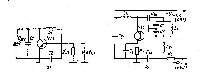
Fig. 22. Autogenerator according to three-point capacitive scheme:
a - equivalent circuit; b - option to build a circuit with an external power supply circuit base When calculating the autogenerators, they are usually given by the values of C and K. The condition of self-excitation: S n R y = l, where S n is the steepness of the static characteristic of the collector current at the resting point. Any oscillator with a transistor can be considered as an amplifier with positive feedback, in which the output gain of the power to the feedback ratio has a modulus equal to one, and the phase angle for the required frequency must be zero. There are a number of typical schemes for autogenerators. Of these, three are the most common: capacitive “three-point” (Fig. 22), inductive “three-point”, with transformer feedback. The condition of phase balance in the autogenerator according to the generalized three-point scheme is expressed by the formula X 9 ъ + Х ak = - Hbkwhere X Uh b, X zk , Hbk- reactance between the corresponding terminals of the transistor. For some reasons, which will be discussed below, preference is given to capacitive "three-point". In the theory of autogenerators for capacitive "three-point" there are formulas: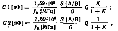 where f K is the frequency of generation. From these formulas it is clear that the capacitance of the capacitors C1 and C2decreases with an increase in the coefficient G. At the same time, the influence of the input and output circuits of the transistor (Cm, gin, Caai) on the non-stability of the frequency of the oscillator becomes noticeable. It should be borne in mind that the capacitances C1 and C2 include, besides the capacitors themselves, the mounting capacitance, the capacitance of the output and input of the transistor, and the capacitances of the connected stages. It is usually recommended to choose G = 2 - 4. The components of the instability due to the change in the parameters of the input and output circuits of the transistor also depend on the feedback coefficient K. There is an optimal value K=
Kowr,
which will ensure maximum frequency stability. The feedback factor K can be selected experimentally. With an increase in the quality factor Q of the oscillator circuit, the influence of the aforementioned components of instability decreases. As already mentioned, the stability of the generator frequency depends on the Q-factor of the circuit and the constancy of its parameters. The phase shift in the feedback circuit of the generator varies with changes in the internal resistance and the input capacitance of the transistor, for example, due to changes in temperature or supply voltage.
where f K is the frequency of generation. From these formulas it is clear that the capacitance of the capacitors C1 and C2decreases with an increase in the coefficient G. At the same time, the influence of the input and output circuits of the transistor (Cm, gin, Caai) on the non-stability of the frequency of the oscillator becomes noticeable. It should be borne in mind that the capacitances C1 and C2 include, besides the capacitors themselves, the mounting capacitance, the capacitance of the output and input of the transistor, and the capacitances of the connected stages. It is usually recommended to choose G = 2 - 4. The components of the instability due to the change in the parameters of the input and output circuits of the transistor also depend on the feedback coefficient K. There is an optimal value K=
Kowr,
which will ensure maximum frequency stability. The feedback factor K can be selected experimentally. With an increase in the quality factor Q of the oscillator circuit, the influence of the aforementioned components of instability decreases. As already mentioned, the stability of the generator frequency depends on the Q-factor of the circuit and the constancy of its parameters. The phase shift in the feedback circuit of the generator varies with changes in the internal resistance and the input capacitance of the transistor, for example, due to changes in temperature or supply voltage. 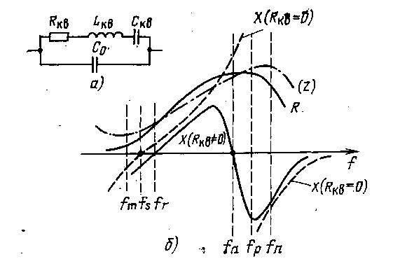 Ric. 23. Equivalent circuit of a quartz resonator (a) and the dependence of the active, reactive and modulus of the complex resistance of a quartz resonator on frequency (b) In high-stable oscillators, electromechanical resonators with high quality and thermal stability sufficient for practice are used as circuits or their elements. The greatest application is found in quartz resonators. -AC voltageapplied to the edges of the quartz resonator causes its oscillations. The resonant frequency of mechanical vibrations is determined by the size of the plate. The resonator dissipates a very small part of the energy, so the quartz resonators have an equivalent Q of Q from 10,000 to 1,000,000. The equivalent circuit of the quartz resonator is shown in Fig. 23. In this contour, if we neglect the loss resistance R kv, there will be two resonant frequencies - a series resonance f t
and parallel resonance f p, defined by the formulas where L KB, C q, Co are elements of an equivalent circuit. Dependence curve reactive resistance quartz from frequency without accounting for losses is shown in fig. 23.6 in dashed line. In the first case (f f) reactive resistance X
is zero, in the second (f p) - infinity. Taking into account losses, the circuit has a complex resistance Z = R + jX. On the same pic. 23 shows dependences of reactive and active resistance and module of complex resistance | Z| =\/
R 2
+
X 2:
on frequency. The frequency difference t p - f 8 = Df is called the width of the resonance interval.
Ric. 23. Equivalent circuit of a quartz resonator (a) and the dependence of the active, reactive and modulus of the complex resistance of a quartz resonator on frequency (b) In high-stable oscillators, electromechanical resonators with high quality and thermal stability sufficient for practice are used as circuits or their elements. The greatest application is found in quartz resonators. -AC voltageapplied to the edges of the quartz resonator causes its oscillations. The resonant frequency of mechanical vibrations is determined by the size of the plate. The resonator dissipates a very small part of the energy, so the quartz resonators have an equivalent Q of Q from 10,000 to 1,000,000. The equivalent circuit of the quartz resonator is shown in Fig. 23. In this contour, if we neglect the loss resistance R kv, there will be two resonant frequencies - a series resonance f t
and parallel resonance f p, defined by the formulas where L KB, C q, Co are elements of an equivalent circuit. Dependence curve reactive resistance quartz from frequency without accounting for losses is shown in fig. 23.6 in dashed line. In the first case (f f) reactive resistance X
is zero, in the second (f p) - infinity. Taking into account losses, the circuit has a complex resistance Z = R + jX. On the same pic. 23 shows dependences of reactive and active resistance and module of complex resistance | Z| =\/
R 2
+
X 2:
on frequency. The frequency difference t p - f 8 = Df is called the width of the resonance interval. 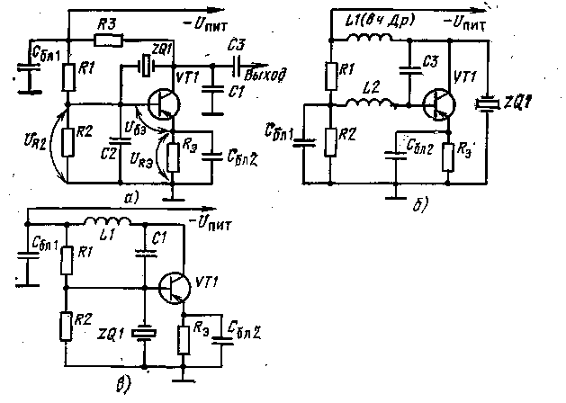
Fig. 24. Variants of the scheme of a quartz generator of parallel resonance, with quartz excited at the fundamental frequency:
but - capacitive "three-point";b, c - inductive "three-point" It is known that the equivalent inductance on nth mechanical the harmonics of the Khvartsa practically does not change as compared with the inductance at the fundamental frequency, the equivalent capacitance is less in p 2 times, and the resonance interval - in n time. It should be noted that the quality factor of the resonator is the highest on the harmonic, which is indicated in his passport as a working one, and accordingly at the frequency indicated on its case. Another common position. Like many other elements, quartz is characterized by permissible power dissipation, the excess of which can remove it from the system. Typically, less than 10% of the power supplied to the generator is dissipated in quartz, which corresponds to 2-4 mW for different types of resonators.Now directly about quartz oscillators. They are divided into parallel resonance (oscillatory) and sequential (filter) generators. Quartz in them can work both at the fundamental frequency and at odd mechanical harmonics. In oscillator generators, quartz is excited at a frequency within the resonant interval, but near a parallel resonance its reactance is inductive. In a sequential resonance generator, the excitation occurs at a frequency near the serial resonance, the reactance of quartz is then zero, and its active resistance is very small.
In fig. 24 shows variants of the parallel resonance generator circuit in which quartz operates at the fundamental frequency. V-amateur designs are the most common generators according to the three-point capacitive scheme, when quartz is connected between the collector and the base of the transistor (Fig. 24, o). They are simple in design and tuning and provide good stability often. In fig. 25 shows a practical diagram of an oscillatory quartz oscillator with a capacitive “three-point” at a frequency of 14.1 MHz and shows its connection with the frequency doubler. In fig. 26 shows a circuit for the excitation of quartz on mechanical harmonics. For this, one of the capacitors of the “three-point” capacitor is replaced by a parallel circuit, which is tuned to the resonance at a frequency lower than the generation frequency. As a result, the circuit will have capacitive conductivity at the frequencies of the desired hormone, and at lower harmonics and at the fundamental frequency, inductive conductivity, which excludes the possibility of generation at lower harmonics and the fundamental frequency. The above explains fig. 27, which presents diagrams of reactive resistance of the sequential and parallel contours. In fig. 27, the following notation is adopted: wL is the resistance of the inductive part of the series circuit; 1 / wС - resistance of the inductive part of the serial circuit; Z is the total resistance of the series circuit; 1 / wL - conductivity of the inductive branch of the parallel circuit; o "C - capacitive conductivity, branches of a parallel circuit; Y is the total conductivity of the parallel circuit. 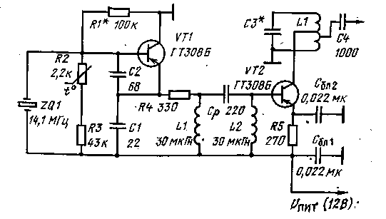
Fig. 25. Diagram of master oscillator and frequency doubler
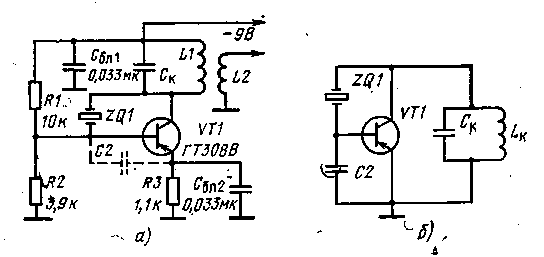 Fig. 26. Scheme of the oscillator (capacitive "three-point") for the excitation of a quartz resonator harmonics(but)
and its equivalent circuit(b)
Oscillator oscillators operating at a frequency higher than 20 MHz usually excite quartz on the third or fifth harmonics, but not higher ones, since it has a stronger effect bad influence static capacity and installation capacity. To calculate the generator, whose scheme is shown in Fig. 25, exist simple formulas for capacitors C1 and C2 (in picofarad), the modulus of the feedback coefficient | K |and high-frequency voltage on the collector (in volts):
Fig. 26. Scheme of the oscillator (capacitive "three-point") for the excitation of a quartz resonator harmonics(but)
and its equivalent circuit(b)
Oscillator oscillators operating at a frequency higher than 20 MHz usually excite quartz on the third or fifth harmonics, but not higher ones, since it has a stronger effect bad influence static capacity and installation capacity. To calculate the generator, whose scheme is shown in Fig. 25, exist simple formulas for capacitors C1 and C2 (in picofarad), the modulus of the feedback coefficient | K |and high-frequency voltage on the collector (in volts): 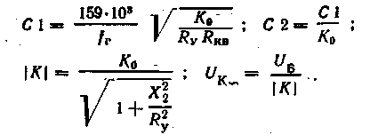 Here Ratis selected on the basis of the under-stressed mode of the oscillator; Hg- capacitance of capacitor C2; To- coefficient determined by the capacitance ratio of capacitors C2 / C1 = 1 / Ko; f g - generation frequency, MHz; Rкв - equivalent active resistance of quartz. In transistor generators series P403, GT308 or similar value Totake equal to 1 - 1.5, and on the transistors of the series P411, GT311 - 0.7 - 0.8.
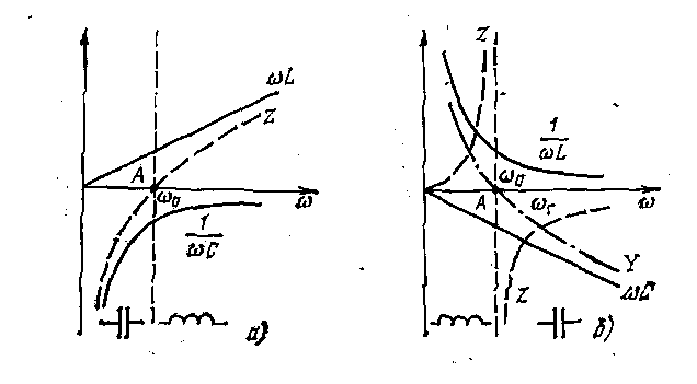
Figure 27 Reactivity Diagrams:
a - sequential contour; b - parallel contour When powering the collector circuits and the base of the transistor from a common Upit source (see Fig. 24, a) the following relationship holds true: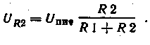 Equivalent resistance in the base circuit
 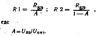 To determine the value of the coefficient BUTyou need in the assembled generator, to install quartz, a temporary divider with a variable resistor to install collector current within 2 - 3 mA. After that, the voltage should be measured. urz,
and then calculate R1 and R2. The resistance of the resistor R 8 determines the temperature stability of the generator. There are recommendations for choosing this resistor. For transistors of the GT308 series, as well as for those close to them, the parameters R 9 are taken equal to 300 Ohms, and for transistors of the GT311 series and similar to them -h-390 ohms. The resistance of the load resistor R3 is defined in the formulas where C1 is the capacitance of the external capacitor, C and is the capacitance of the installation (3-5 pF); ch and Svikh - input and output capacitances of the transistor at the generation frequency By analogy C2 "= C2 + C M + C BX .
The capacitance of the capacitor-SZ is determined from the ratio C3 = (0.01 - 0.1) C1. Capacity of blocking capacitors (in picofarad) is calculated by the formulas
To determine the value of the coefficient BUTyou need in the assembled generator, to install quartz, a temporary divider with a variable resistor to install collector current within 2 - 3 mA. After that, the voltage should be measured. urz,
and then calculate R1 and R2. The resistance of the resistor R 8 determines the temperature stability of the generator. There are recommendations for choosing this resistor. For transistors of the GT308 series, as well as for those close to them, the parameters R 9 are taken equal to 300 Ohms, and for transistors of the GT311 series and similar to them -h-390 ohms. The resistance of the load resistor R3 is defined in the formulas where C1 is the capacitance of the external capacitor, C and is the capacitance of the installation (3-5 pF); ch and Svikh - input and output capacitances of the transistor at the generation frequency By analogy C2 "= C2 + C M + C BX .
The capacitance of the capacitor-SZ is determined from the ratio C3 = (0.01 - 0.1) C1. Capacity of blocking capacitors (in picofarad) is calculated by the formulas 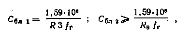 Where Ke- resistance in ohms; f g - frequency in megahertz. Let us turn to a variant of a generator with capacitive “three-fine” and quartz, which works on an odd mechanical harmonic (see Fig. 26). There's the role of a condenser C1the circuit of the oscillator plays a parallel circuit C K L K (see Fig. 26.6). As already noted, at the generation frequency this circuit must have capacitive resistance, i.e. its resonant frequency fo
should be lower than the generation frequency. The parameters of the contour should be chosen so that ownthe frequency was equal to fо =. (0.7 - 0.8) f g. Referring to fig. 27.6. At the frequency W P there is a resultant capacitive conductivity B = w g C eq = w g C "k -1 / w g L TO where c to and L K -
the capacitance and inductance of the circuit, respectively. Usually inductance L K
due to constructive considerations. The capacitance C EC in choose equal to the capacitance of the capacitor C1, determined by the method outlined above. After that we get:
Where Ke- resistance in ohms; f g - frequency in megahertz. Let us turn to a variant of a generator with capacitive “three-fine” and quartz, which works on an odd mechanical harmonic (see Fig. 26). There's the role of a condenser C1the circuit of the oscillator plays a parallel circuit C K L K (see Fig. 26.6). As already noted, at the generation frequency this circuit must have capacitive resistance, i.e. its resonant frequency fo
should be lower than the generation frequency. The parameters of the contour should be chosen so that ownthe frequency was equal to fо =. (0.7 - 0.8) f g. Referring to fig. 27.6. At the frequency W P there is a resultant capacitive conductivity B = w g C eq = w g C "k -1 / w g L TO where c to and L K -
the capacitance and inductance of the circuit, respectively. Usually inductance L K
due to constructive considerations. The capacitance C EC in choose equal to the capacitance of the capacitor C1, determined by the method outlined above. After that we get: 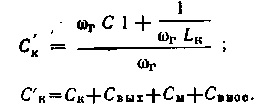 Generalized contour capacity WITH" to
(in pF) can be determined by asking inductance L K
(in μH), according to the formula:
Generalized contour capacity WITH" to
(in pF) can be determined by asking inductance L K
(in μH), according to the formula: 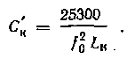 Specific capacitor capacitance C to: WITH TO = C " to - WITH out -
L M - WITH into the nose .
In determining C, HVs are based on the nature of the connection of the buffer to the oscillator. Three variants of external load connections are possible (Fig. 28) - with inductive, autotransformer and external capacitive coupling.
Specific capacitor capacitance C to: WITH TO = C " to - WITH out -
L M - WITH into the nose .
In determining C, HVs are based on the nature of the connection of the buffer to the oscillator. Three variants of external load connections are possible (Fig. 28) - with inductive, autotransformer and external capacitive coupling. 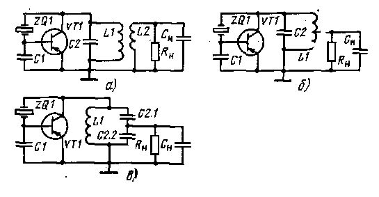
Fig. 28. Equivalent circuits of a three-point em-type oscillator with the operation of a quartz resonator on mechanical harmonics:
a - the connection with the load is inductive;b - autotransformer connection with load;at - external load coupling The connection with the load is selected from the condition of optimal coordination: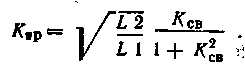 Here Ktr - transformation ratio; L2 is the inductance of the coupling coil with the load; L1
- the inductance of the loop coil, for example, for a frequency in the range of 20–30 MHz is chosen to be equal to 0.6 μH; TO st.
- the coupling coefficient between the coils, determined by the formula:
Here Ktr - transformation ratio; L2 is the inductance of the coupling coil with the load; L1
- the inductance of the loop coil, for example, for a frequency in the range of 20–30 MHz is chosen to be equal to 0.6 μH; TO st.
- the coupling coefficient between the coils, determined by the formula: 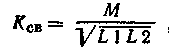 Where
Where 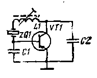 Fig. 29. Equivalent circuit of a quartz-th oscillator with a quartz in an inductive branch capacitive«
three points
Fig. 29. Equivalent circuit of a quartz-th oscillator with a quartz in an inductive branch capacitive«
three points Consider generators with quartz in the circuit, designed to work with a frequency in the range of 5 - 50 MHz. In fig. 29 shows a diagram of a generator with a capacitive “three-point” and with quartz in the inductive branch of the tour. The capacitance of the generator circuit is composed of successively connected capacitors C1 and C2.
The generation takes place at a frequency close to the frequent series resonance of quartz, in which in this case the total resistance is minimal and has an active character. L1 coil (with overlap by inductance no less than two times) can adjust the generation frequency within ± (20 - 50) 10 -6 from nominal value. The inductance Katushev Ll (in μH) is determined by the formula  where C1 and C2 are capacitors in pF; f g - frequency in MHz.
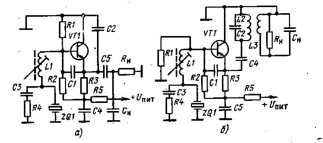
Fig. 30. Schemes of a generator with a quartz resonator operating near a series resonance:
4. DISCRETE CONTROL EQUIPMENT
The movement of the model can be controlled by one-time (discrete) commands. The nature of these commands transmitted by the operator depends on the type of the executive mechanism on the model. In cases where the commands are used to turn on and off actuatorsthey are short lived. When driving rudders, the duration of the command determines the required steering angle of the steering wheel.