Stabilized DC power supply series US-24 is designed to provide a stable output voltage from 0 to 24 V with an adjustable charge current from 0 to 3000 A. The output voltage of such a device is independent of mains voltage and from the change in the load current.
The stabilized US-24 power supply provides operation in the mode of current stabilization and in the mode of voltage stabilization, therefore it can be used as a constant voltage source and as a constant current source.
Decoding of stabilized power supplies of the US series
The user can independently set the current and voltage limiting parameter, in the entire range of the source operation in steps of 0.1A and 0.1V. It is also possible to create complex multi-step algorithms for changing the output voltage and current limit and depending on the current and voltage, the elapsed time or the temperature change (when ordering an external temperature sensor)
The possibility of programming the operating mode, provides a wide range of applications of these devices.
Stabilized power supplies of the US-24 series can be used as:
- rectifiers for galvanic processing of metals;
- installations for heating workpieces;
- power supplies for DC motors;
- rectifiers for railway equipment;
- power supplies for communication systems;
- powerful laboratory power sources.
The stabilized power supply of the US-24 series has the ability to connect an external temperature sensor, as well as programming the output voltage and limiting the current depending on the temperature.
The main advantage of the stabilized DC power supply of the US-24 series is the use of a group of high-frequency impulse converters operating at a common load.
Programmable power supply series US-24 provides a high quality of stabilization of output parameters, t. each of the converters operates in a narrow range of output characteristics - this allows you to adjust the source to a high quality of parameter stabilization in the entire range. Thus, in the case of operation at low voltages, only a part of the transducers in the group works, and when the output voltage rises, additional transducers are connected.
When working on small currents, only one group of transducers is involved, with an increase in the output current, the other groups are automatically connected. Thus, high conversion efficiency and high quality of current and voltage stabilization in the whole range are ensured.
A distinctive feature stabilized power supply series US-24 production company "KRON" is a higher reliability of the product as a whole. In products with a network transformer, reliability depends on the quality of the network transformer and thyristor rectifiers. The failure of any element of such a system leads to its complete inoperability. When using a group of high-frequency converters, if any of the transducers fails, the operability of the product as a whole remains, only the maximum output power decreases by the amount of the failed converter.
The power supplies of the US-24 series are relatively small in size and weight with a high output power. As a rule, low-frequency linear transformer circuits with a thyristor stabilization scheme for output parameters are used to obtain similar output powers.
If we compare two transformers with a power of 2.5 kW operating at a frequency of 50Hz and 60kHz, then the high-frequency transformer will be about 10 times smaller and 50 times lighter than a low-frequency transformer. Therefore, the use of several high-frequency modules instead of one network transformer gives a significant gain in weight and overall characteristics of the entire product as a whole.
Classification of stabilized DC power supplies of the US-24 series
| Classification | Description |
|---|---|
| By power | Sources of low power - up to 100 watts per channel. Medium power - up to 300 W High power - over 300 watts. |
| By number of channels | Modern power sources have more than one adjustable output, and two or more. Most often two outputs are basic, they can be connected in series to increase the output voltage or in parallel to increase the maximum current. |
| According to the principle of action | The sources of direct current are divided into linear or impulse. Linear architecture uses a powerful network transformer and an adjustment circuit. Also this category has a low level of radiated interference. Due to this structure, the structure has a lot of weight. Pulsed sources are distinguished by the method of converting energy into alternating current of high frequency. Transformers of pulsed DC sources have a frequency higher than 50 Hz and mass is less than that of linear ones. Due to smaller dimensions, the devices are quite common, although they radiate a greater level of interference. |
General characteristics of the stabilized DC power supply series US-24
* You can select colors according to individual order
Individual characteristics, depending on the version
| product name |
Maximum output charge current, A | Maximum output voltage, V |
|---|---|---|
| US-100-24 | 100 |
24
|
|
US-200-24 |
200 | 24 |
|
US-300-24 |
300 | 24 |
|
US-400-24 |
400 |
24
|
|
US-500-24 |
500 | 24 |
|
US-600-24 |
600 | 24 |
|
US-700-24 |
700 | 24 |
|
US-800-24 |
800 | 24 |
|
US-900-24 |
900 | 24 |
|
US-1000-24 |
1000 | 24 |
|
US-1500-24 |
1500 | 24 |
|
US-2000-24 |
2000 | 24 |
|
US-2500-24 |
2500 | 24 |
|
US-3000-24 |
3000 | 24 |
At the request of the customer, the stabilized power supply of the US series can be manufactured according to the North American standard (with supply voltage 110/480 V and frequency of current 60 Hz).
Note: Weight and dimensions can be changed without warning of the customer.


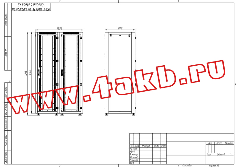
Drawing of stabilized DC power supply series US-24 (housing type - 2)

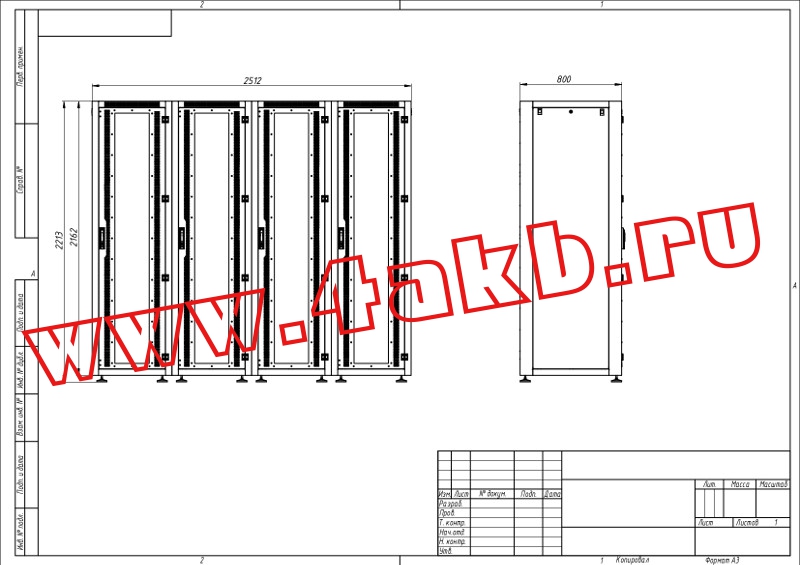
Drawing of stabilized DC power supply series US-24 (housing type - 3)
Drawing of a stabilized DC power supply series US-24 (housing type-4)

Drawing of stabilized DC power supply series US-24 (housing type - 5)
Basic device control is carried out by means of a symbolic liquid crystal display and 4 buttons: "Start / Stop", "Parameter", "Up", "Down" located on the front panel.
The user can select from the list the charging algorithm (written in the internal memory of the switchgear), specify the nominal battery voltage, set the maximum permissible current, and set the maximum permissible charging time.
During the charging process, the user is shown: the current charge algorithm (charge method), the current charge stage (stage), current and set current and voltage, elapsed time, and transferred to the battery or battery capacity in AH. The value of the capacity can be either positive or negative. A positive number means that the battery was given a charge, negative - a charge was consumed from the battery.
Figure 1 shows the type of LCD:

During operation, by pressing the Parameter button, you can toggle the displayed parameters: display the time and capacity or display the temperature of the switchgear (Figure 2).

Figure 2 - LCD when displaying temperature
In the event of an alarm, the message "Error" appears in line # 1 with the following error number, while line # 4 will decode this error, which facilitates the diagnosis of the fault (Figure 3).

At the end of the charge, the device automatically turns off and "Completed" appears, with the value of the elapsed time and the transferred / consumed capacity remaining. Thus, at the end of the charge, you can check how much the battery has been fully charged (Figure 4).

When used with a liquid crystal display, at least one charge regime ("Charge") and one discharge mode ("Discharge") are mandatory in the ZRU from the factory. Also from the plant can be downloaded additional automated charging methods for acid and alkaline batteries, for example:
- "Acid AB" - an automatic method for charging acid batteries;
- "Alkaline AB" - an automatic method for charging alkaline batteries;
- "Desulfate." - an automatic method for desulphurizing acid batteries;
- "Charge imp." - battery charge by current pulses;
- "Discharge imp." - discharge of AKB by current pulses;
These algorithms, except for "Charge" and "Discharge", may not be present in the internal memory of the device. Other charging techniques may also be added or the algorithms of the listed can be changed. The presence or absence of one or another charging technique depends on the modification of the product and on the type of charge-discharge module supplied with the product. Also, data or other methods can be written to the internal memory of the device in agreement with the customer.
If the product has a USB or Wi-Fi interface for connecting a PC, the user can independently download the above methods into the device memory, and can create new ones for any battery types.
ATTENTION!!!When using the charging techniques "Acid AB", "Desulfate.", "Alkaline AB", etc., with the exception of the methods "Charge" and "Discharge", in the field:
"CURRENT": the maximum permissible value of the charge current is set at the basic stage of the charge. "VOLTAGE": Sets the RATED VOLTAGE of the battery.
ATTENTION!!!The "Charge" and "Discharge" methods of service are not automated and provide charge and discharge of the battery only with the limitations of current and voltage set by the user, as is done in classic chargers without microprocessor control. The user must select the thresholds for limiting the charge / discharge current and voltage in these methods independently according to the instruction manual for the battery being charged.
When specifying the current and voltage limits, it is necessary to remember: incorrect setting of the current and voltage thresholds (which do not comply with the battery manufacturer's recommendations) can result in undercharging or recharging the battery or even damage to the battery.
The necessary current and voltage limits depend on the type, capacitance and rated voltage of the battery.
The KRONEnergy program allows you to configure, program to start and stop the stabilized US-24 DC power supply, display data and operation parameters.
Running the program
The KRONEnergy program is supplied integrated into the control panel of the power supply and starts automatically immediately after the remote control is turned on.
After starting the system, the main screen form shown in Figure 1 will appear on the monitor.

The system will automatically scan the presence of connected rectifiers and establish a connection with them.
The main screen form is divided into 3 conventional parts:
- upper part: setup and start menu;
- right side: current parameters;
- graphs of current, voltage and temperature.
The main part of the screen is occupied by the graphs of the output current and voltage, as well as temperature charts. The temperature graph displays simultaneously several graphs for all temperature sensors, and data can be displayed both from external temperature sensors intended for measuring the temperature of the load and from internal temperature sensors designed to measure the temperature of the rectifiers.
In the upper right part, below the buttons with the settings, the current readings of current and voltage are displayed.
The status field displays the current errors in the operation of the rectifiers.
Below the "state" field is the "Events" field, which displays the start time of the operation, the transition time from stage to stage during program execution, errors occurring during operation, as well as additional information characterizing the current status of the rectifiers (Figure 2).

To create the source work program, use the Template button. When you click it, the window shown in Figure 3 appears.

After clicking "+" or "Edit", the method editor window opens, as shown in Figure 4.

In the name field, you enter a unique name for the method (program).
The parameters "Max. current "and" Max voltage "are the current and voltage for this method, with respect to which the current and voltage of all stages are set. In these fields, you must specify the maximum allowable current and voltage for this method. These parameters are copied to the corresponding fields "Current" and "Voltage". All currents and voltages of all stages are attached to the parameters in these fields as a percentage. This is made for ease of use. For example, if you need to change the current or voltage, but keep the algorithm of the program, then the basic form simply change the current and voltage parameters, while the currents and voltages of the stages (steps) change in the same ratio: "method current / main current form "and" voltage of the method / voltage of the screen form. "
The parameter "Temporary method limitation" is intended to prevent endless work of the source if the end conditions are not set correctly. It is recommended that this parameter be set to 1.5 times the estimated program time.
The "Number of cycles" field is used to enable the repeat mode of the method, the specified number of times.
The graph of the constructed method (program) is displayed in the lower part of the window. This graph displays the current changes that will occur when this program is running. The given schedule is reconstructed automatically at change of stages (steps) of a method and allows to estimate correctness of the created method.
The buttons "Add", "Modify", "Delete" are used to add, change or delete the steps (steps) of the edited method, respectively. When you click the "Add" or "Edit" button, the stage edit window (steps) opens, as shown in Figure 5.

The "Stage type" field specifies the functions that will be performed by the rectifier at this stage (step). If "On" is selected, the set current and voltage are applied to the load. The current and voltage are specified below in the "Characteristics" field.
When selecting "Impulse", the current pulse will alternate with a pause. The current and voltage are set in the "Characteristics" fields. Pulse durations are set in the "Time" field.
Manual mode of operation
Manual mode of operation is designed to start the rectifier, with the limitation of current and voltage without performing an automatic program of work.
Before starting the product must be turned on, the product must be connected to the load and temperature sensors, if necessary.
To enable in manual mode, you must perform the following actions (see Figure 6):
- In the program field, select "Manual mode".
- Set the current limit (when this voltage is reached, the voltages will decrease).
- Specify the voltage limit (when this voltage is reached, the current will decrease).
- Press the "START" button.
In order to stop the work of the source, you must press the "Start" button.
Working in automatic mode
Automatic mode is designed to execute the user-created work program of the source.
Before starting automatic mode, the product must be switched on, the load must be connected to the product, temperature sensors (if necessary), no error messages should be displayed.
Before starting the system in the automatic mode, you must first create a method (program).
To start the automatic mode, you need to perform the following sequence of actions (see Figure 6):
- Select the program created earlier.
- Check the current limit value (this parameter will be read automatically from the selected program).
- Check the value of the voltage limit (this parameter will be read automatically from the selected program).
- Start the algorithm for execution by pressing "START".
In automatic mode, the system will execute the selected work program of the source. In this case, the system will automatically go from step (stage) to a stage (stage), and will stop working when the end conditions specified by the user are fulfilled.
The current and voltage limit fields in this mode are automatically filled in from the selected program. However, the user can change them manually in order to limit the maximum current or voltage while the system will automatically reduce the currents or voltages of all program steps in proportion to the user-made changes. After the end of the program with the changed parameters, all program values will return to the original value.
It would seem that this device is not so important, the power supply unit, because the market is simply swamped by them from different manufacturers, and often the quality leaves much to be desired. And the one who faces the problem of choice, often does not even think that it is from this small device that the quality and correctness of the work of other devices directly related to it depends. This is especially true for security and alarm systems. It should be noted that the 24V DC power supply or alternating current - this is the simplest device in the security alarm system and in terms of their functionality, and in terms of design.
But the most important thing is that this very simplicity has brought to the market such a huge number of manufacturers. And what does this usually lead to? To competition, where some manufacturers simply deceive consumers, advertising low-quality goods, assuring that it is the best. This is usually the case for consumers. And since there are no generally accepted standards for power supplies, it is simply impossible to make claims for low quality.
Many can say that almost all power supplies present in the current market have a quality certificate. Let's just say the certificate is not a guarantor. After all, it indicates only the tested parameters of the device, which the manufacturer declares in the technical documentation.
Classification of DC units
If we talk about the type of use, then all the blocks can be divided into two groups:
- Uninterruptible power supplies - BBP.
- Backup power units - BRP.

BBP
Usually these devices are used in those cases when the equipment does not have its own power source. The very name of the device indicates that the unit provides the equipment with power with a certain load. And this load is always constant. Therefore, the device consists of a powerful network power source, battery, battery charger and switch, which transfers the load from the power source to the battery. By the way, the switch is the simplest scheme.
BRP
This option is designed to provide power to electrical or electronic systems in those cases where there is no main source, that is, the supply of electricity from the 220-volt power supply is disconnected. They are usually installed to equipment in which there is no access to backup power and there is no built-in power source. In simple terms, these are the usual chargers for batteries or protection systems.

Attention! Uninterruptible DC power supply can also be used as a backup. But the BRP can not be used as a BBP. In addition, redundant power supplies are almost an order of magnitude cheaper than permanent ones. The thing is in the absence of a high-power network converter in their design.
There is one more nuance that consumers pay little attention to. You can label it as follows. There are some models of power supplies, which in the continuous mode give a current of a lower value than in the standby mode. Why is this happening? In view of the fact that the backup power is the supply of electricity from the battery, it is necessary to understand that the battery can deliver a current of high power. In some situations this is undesirable, therefore protective circuits are installed in the feeding circuit.
For example, the situation related to the operation of the fire extinguishing system can be cited. In the normal mode, when only the monitoring equipment is operating, the current capacity requirements are minimal. There is an uninterrupted supply of electricity. As soon as a freelance situation happens, that is, the entire fire-fighting system is turned on, without great power it can not be avoided. And this is just a backup option. Therefore, in this case, the backup systems act as a power source (main and auxiliary). That is, there is no need to install both the BTS and the PDU.

Classification of circuit solutions
There are only three classes, each of which differs from the others in the way of constructing the stabilizer. In these units it must be powerful and low-voltage.
Stabilizer without transformer
Talk about this power supply can be so - many drawbacks, the advantages are doubtful. The merits include small size and weight. The biggest drawback is the low efficiency. Therefore, these blocks are of low popularity. Usually they are installed in TVs and computers. Perhaps, that's all. The disadvantage is the impossibility of permanent work. That is, such power supplies must be switched off during the day. Therefore, they are not installed in various systems (security, fire). Although experts say that the future is precisely behind these modifications. It is important to properly staff them.

PWM Stabilizers
If we talk about the merits, then this is a high efficiency, plus an acceptable price (one of the lowest) if a stabilizer is used, which operates at a current higher than 3 A. Unfortunately, the disadvantages are also present, where the most important is low reliability. It should be noted that PWM stabilizers are increasingly used in systems where there is a need to convert one voltage to another. Therefore, they are installed on power supplies, where there are two outputs: one for alternating current, the second for constant.
Linear stabilizers
Experts agree that these are the most reliable stabilizers of all those present on the market. Disadvantages also exist - these are large dimensions and weight of products, plus a high price. Unfortunately, efficiency is not very high.

But here is what experience shows. The choice of a 24 VDC power supply depends on the system in which it will be used. If it concerns the systems of signaling, protection and fire extinguishing, then on the first place there are such characteristics as margin of safety (long-term operation) and reliability of the device. Therefore, consumers are increasingly choosing linear models.
- First, they easily tolerate the atmospheric effect.
- Secondly, they do not interfere with nearby equipment.
- Thirdly, if you select a power supply up to 2 A, then this is the cheapest product from the entire proposed line.
- Fourth, we should not discount the entire upward trend in reducing electricity consumption by various types of equipment. So linear power supplies for 24 volts will be classics for a long time.
Output voltage
Not all consumers know that the voltage at the output of some power supplies is maintained exactly 24 volts, some models do not have this accuracy. In some devices, the output voltage can be adjusted. That is, and here diversity is present. It turns out that the power units that work in the standby mode, gradually reduce the voltage as the battery exhausts. Therefore, the stability of the work depends on the capacity of the battery. But there are also devices on the market, in which the voltage does not fall. Usually these are PWM converters, in the construction of which there are complex circuits.
Therefore, when choosing a 24 V DC power supply, you need to make sure that the device can produce a stable voltage (that is, the range of this value is determined). Hence, in principle, and the long-term performance of all equipment. By the way, be sure to pay attention to this indicator, which manufacturers necessarily indicate in the product's passport. Some companies indicate a range of voltages when working on the network, and when working on batteries.
Input voltage
Here the situation is completely different. The thing is that in the Russian power lines (by the way, according to GOST), the voltage can vary from the nominal (220V) within ± 10%. What does it say? There are two positions:
- If the supply voltage is minimal and the current is maximum, then the voltage range of the power supply unit can guarantee and at the same time maintain the stability of the voltage itself.
- If the voltage is the maximum and the same can be attributed to the current, then no stabilization can not be said. Just the block overheats. There's a big problem for you.

Especially the situation is aggravated if the temperature the environment increased (this applies to the summer period). What do some manufacturers do in this situation? They simply underestimate the range of stresses. But this does not make the consumer better. After all, in some regions of Russia the voltage in the network is about 190 volts is the norm. Hence the consequences:
- The batteries are not fully charged.
- The operating time of power supplies is reduced.
- Stalling failure, especially with a sudden surge in current consumption.
Output current
To be honest, everything that was said above is, to put it mildly, a secondary criterion of choice. Because the main parameter of DC power supply units is the output current, that is, the rated current of the load.
Attention! Remember once and for all, the rated load current must be transferred from the mains to the load always and constantly, regardless of the circumstances of the device. It must act all the time of consumption without distortion, decrease and increase. Regardless of what voltage is in the network or from the battery, what is the ambient temperature, there are its differences or not.
All other parameters are optional or auxiliary. Some manufacturers indicate a huge number of quantities and characteristics. Do not enter them, you just cloud your head.

- And if the rated current of the load is neither indicated in the passport nor on the body of the unit, it means that you have a useless piece of metal in front of you.
- If you find this inscription: "rated load current without battery", then know that through the network it can be nominal, and through the battery is too low.
- Read the power supply passport carefully, then make a purchase.
- Install only devices from one manufacturer on one site.
- Try to purchase domestic power supplies, they are manufactured under Russian operating conditions.
- Protection is the basis of long-term service, so pay attention to whether there is a protection of the battery from the deep discharge in the circuit of the unit.
Do not buy cheap devices from China.
Similar entries:
All electronic equipment is powered by DC sources. For mobile equipment, as a rule, batteries or galvanic batteries are used. Now there is a lot of such equipment in the hands and pockets: it's mobile phones, cameras, tablet computers, various measuring instruments and much more.
Stationary electronics, - televisions, computers, music centers, etc. It is powered from the AC mains by means of power supplies. Here, by no means do not use batteries or small batteries.
Electronic devices are often not self-contained and operate "on their own". First of all, these are built-in electronic components, for example, the control unit washing machine or microwave oven. But even in this case, the electronic units have their own separate, often even stabilized, and even with protection, which allows to protect both the power supply unit itself and the load, i.e. connected control unit.
In the designs developed by radio amateurs there is always a power supply unit, if, of course, this design is brought to the end, and not abandoned halfway. Unfortunately, this happens quite often. But in the general case, the construction of a scheme consists of several stages.
Among them is the development of conceptual framework, as well as assembling and debugging it on the breadboard. And only after obtaining the required results on the breadboard, begin to develop a capital construction. Then they develop the circuit boards, the case and the power supply.
During the experiments on the breadboard, the so-called are most often used. One and the same block has to be used for adjusting the most diverse designs, so it must have ample opportunities.
Typically, this is a unit with output voltage regulation, and providing sufficient current. Sometimes the power supply delivers several voltages, such units are called multi-channel. An example is a conventional computer power supply or a bipolar source for a powerful UMZCH.
When the power supply unit is designed for one fixed voltage, for example 5V, it is quite good to provide protection from exceeding the output voltage: if the output transistor of the stabilizer has broken, then the circuit that feeds from it can suffer.
Although this kind of protection is not very complicated, only a few details, in industrial schemes it is for some reason not made, and it is found only in radio amateur designs, and even not in all. But, nevertheless, there are such protection schemes.
If you look closely at devices - consumers, you can see that all electronic devices are powered by voltages from the standard range. This is, first of all, 5, 9, 12, 15, 24V. Based on these values, a number of integral stabilizers with fixed voltages are produced.
In appearance, these stabilizers resemble a conventional transistor in the TO-220 package (similar to the KT819) or in the D-PAK package for surface mounting. The output voltage has the values 5, 6, 8, 9, 10, 12, 15, 18, 24V. These voltages are reflected directly in the marking of the stabilizers applied to the body of the device. Approximately it might look like this: MC78XX or LM78XX.
In datasheets it is written that these are three-output stabilizers with a fixed voltage, as shown in Figure 1.

Picture 1.
The scheme of inclusion is extremely simple: only three feet were soldered and a stabilizer with the required voltage and output current from 1 ... 2А was obtained. Depending on the particular stabilizer used, the currents change, which should be noted in the documentation. In addition, integral stabilizers have built-in protection against overheating and protection by current.
The first two letters indicate the manufacturer's firm, and the second XX is replaced by digits showing the stabilization voltage, sometimes the first two letters are replaced by one ... three or not indicated at all. For example, the MC7805 stands for a fixed-voltage stabilizer of 5V, and the MC7812 is the same, but with an output voltage of 12V.
In addition to stabilizers with fixed voltages in the integral version, there are adjustable stabilizers, for example LT317A, the typical switching circuit of which is shown in Fig. 2. The voltage regulation limits are also indicated there.

Figure 2. Typical scheme of switching on the adjustable regulator LT317A
Sometimes there is simply no adjustable regulator at hand, how to solve this problem, can you do without it? Well, we need a voltage of 7.5V and that's it! It turns out that from a stabilizer with a fixed voltage it is easy to obtain an adjustable one. A similar circuit is shown in Figure 3.

Figure 3.
The adjustment range in this case starts from the fixed voltage of the applied stabilizer and is limited only by the value of the input voltage, naturally, minus the minimum voltage drop across the regulating transistor of the stabilizer.
If voltage adjustment is not required, but instead of 5V it is required to obtain, for example, 10, simply remove the transistor VT1 and everything connected with it, and instead turn on a zener diode with a stabilization voltage of 5V. Naturally, the zener diode turns on in the non-conductive direction: the anode is connected to the negative power bus, and the cathode to the 8 (2) stabilizer terminal.
Attention is drawn to the numbering of the conclusions of the three-legged case, shown in Fig. 3, namely: 17, 8, 2! Where did it come from, who invented it - it's unclear. Perhaps this is again the machinations of our developers, so that "theirs" are not guessed! But such a pin is used, and this has to be tolerated.
After the integral stabilizers were considered, it is possible to switch to the manufacture of power supplies based on them. To do this, you only need to find a suitable transformer, supplement it with a diode bridge with an electrolytic capacitor, and all this is assembled in a suitable enclosure.
Laboratory power supply
Starting to develop a laboratory power supply, you need to determine its element base, or, simply speaking, from what we will do it. The easiest way is to assemble the desired block on the LT317A chip or its domestic analog KR142EN12A (B) - adjustable voltage regulators.
Let's return to figure 2. It says that the voltage regulation range is 1.25 ... 25V. The maximum permissible value of this parameter is up to 1.25 ... 37V, with an input voltage of 45V. This is the maximum permissible voltage, so it is better to limit the 25 volt regulation range.
For maximum current (1.5A), too, it is better not to chase, so we will proceed from the calculation of at least one ampere, which is just 75%. As there is no margin of safety must always be. Therefore, for such a power supply you need a rectifier with a voltage of at least 30 ... 33V and a current of up to 1A.
C is shown in Figure 4. If the current consumption is more than one ampere, the stabilizer should be supplemented with external high-power transistors. But this is another scheme.

Figure 4. Rectifier circuit
Calculation of the rectifier and transformer
First of all, it is necessary to choose the rectifier bridge diodes, their direct current must also be at least 1A, and better, if at least 2A or more. Diodes 1N5408 with direct current 3A and reverse voltage of 1000V are quite suitable here. Domestic diodes KD226 with any letter index will also suit.
The electrolytic filter capacitor can also be easily selected, using practical recommendations: for each ampere of the output current, one thousand microfarads. If we plan a current of no more than 1A, then a 1000μF capacitor is suitable. Electrolytic capacitors, unlike ceramic capacitors, do not tolerate increased voltages, so the circuits always indicate their working voltage, which should be higher than the real one in this circuit.
A capacitor of 1000μF * 50V is required for the designed power supply. Nothing bad will happen if the capacity of the capacitor is not 1000, but 1500 ... 2000μF. Actually, the rectifier is already designed. Now, as they say, the case for small: it remains to calculate the transformer.
First of all, determine the power of the transformer. This is done taking into account the load capacity. If the output current of the stabilizer is 1A, and the input voltage of the stabilizer is 32V, then the power consumed from the secondary winding of the transformer P = U * I = 32 * 1 = 32W.
What kind of transformer is required at this power of the secondary circuit? All depends on the efficiency of the transformer, the larger the overall power, the higher the efficiency. This parameter is also affected by the quality and design of the transformer iron. The table shown in Figure 5 will help determine this issue.

Figure 5.
To know the overall power of the transformer, the power in the secondary winding must be divided by the efficiency of the transformer. Suppose that we have at our disposal a conventional transformer with a W-shaped iron, designated in the table as "armored stamped". The design power of the designed power supply is 32W, then the power of the transformer is 32 / 0.8 = 40W.
As it was written just above, the developed power supply requires a constant voltage of 30 ... 33V. Then the voltage of the secondary winding of the transformer will be 33 / 1,41 = 23,404V.
This allows you to select a standard transformer with a secondary winding voltage at idle 24V.
In order not to complicate the calculations, the voltage drop across the bridge diodes and the active resistance of the secondary winding is not taken into account here. Suffice it to say that at a current of 1A, the diameter of the secondary wire is usually taken to be at least 0.6 mm.
Such a transformer can be selected from unified transformers of the CCI series. The power of the transformer can be more than 40W, this will only improve the reliability of the power supply, although it will slightly increase its weight. If the transformer TPP was not acquired, then you can simply rewind the secondary winding of a suitable power transformer.
If a bipolar regulated power supply is required, it can be assembled according to the scheme shown in Figure 6. To do this, you need a voltage regulator of negative polarity KR142EN18A or LM337. The scheme of its inclusion is very similar to KR142EN12A.

Figure 6. Diagram of a bipolar regulated power supply
It is quite obvious that a bipolar rectifier will be needed to power this stabilizer. The easiest way to do this is with a mid-point transformer and diode bridge, as shown in Figure 7.

Figure 7. Diagram of a bipolar rectifier
The design of the power supply unit is arbitrary. The rectifier itself and the stabilizer board can be assembled on separate boards or on one. The microchips should be installed on radiators with an area of at least 100 square centimeters. If you want to reduce the size of the radiators, you can apply forced cooling with the help of small computer coolers, which are now available for sale.
A somewhat improved scheme for switching on the stabilizer is shown in Figure 8.
Figure 8. Typical scheme for incorporating KR142EN12A
Diodes VD1, VD2 protective type 1N4007 are designed to protect the chip from breakdown in the case when the voltage at the output exceeds the voltage at the input. This situation can occur when the chip is turned off. Therefore, the capacity of the electrolytic capacitor C2 should not be greater than the capacity of the electrolytic capacitor at the output of the diode bridge.
The Cadj capacitor connected to the control terminal significantly reduces the ripple at the output of the stabilizer. Its capacity is usually several dozen microfarads.
In the design of the power supply it is desirable to provide a built-in voltmeter and an ammeter, better electronic, which are sold in online stores. That's only the prices they bite, so at first it's better to do without them, and set the required voltage using a multimeter.