capacitor as a damping resistor
It is known that a capacitor installed in a circuit alternating current, has a frequency-dependent resistance, and is called reactive. Using a capacitor as a resistance also allows to extinguish the excessive voltage of the network, and the power on the reactance is not released, which is a great advantage of the capacitor in front of the quenching resistor. As calculation of the resistance of the capacitor to alternating current , respectively, and the impedance Z of the circuit composed of a series-connected load with an active resistance Rn and a capacitor with a reactance Xc is equal to
then direct calculation of the capacitance of the quenching capacitor
rather complicated. To determine the value of the capacitor used as a quenching resistor, it is easier to use the nomogram shown in the figure.  On the nomogram along the abscissa axis, the resistances Rn are plotted in kOhm, along the ordinate axis is the capacitance C of the quenched capacitors in uF and along the axis drawn at an angle of 45 ° to the abscissa axis, the impedances Z of the circuit in kOhm.
To use the nomogram, you first need to determine the Rn and Z by Ohm's law or by the power formula. On the abscissa of the nomogram, find the calculated value of Rn and draw a vertical line parallel to the ordinate from this point. Then a certain value of Z is sought on the inclined axis. An arc is drawn from the origin point through the point Z, which must intersect the line drawn parallel to the ordinate axis. From the point of intersection, a line parallel to the abscissa axis is drawn. The point where this line meets the ordinate axis will indicate the required capacitance of the quenching capacitor.
Example 1. Determine the capacitance of the capacitor, which must be connected in series with the electric soldering iron 127 V, 25 W, so that it can be plugged into an alternating current network with a voltage of 220 V.
We find Rn:
where U is the voltage to which the soldering iron is designed, P is the power of the soldering iron.
To determine Z, it is necessary to know the current I flowing in the circuit:

Then Z is equal to:
How to find the capacitance of the quenching capacitor, using the calculated preliminary data, is shown on the nomogram in bold lines.
Example 2. A classic bridge rectifier (Figure 2)  with an output voltage Uout = 18 V and an load current In = 20 mA, it is necessary to feed from a 127 V power supply. Find the capacity of the capacitor C1, which must be connected in series with the rectifier to extinguish the excess voltage.
Determine the load resistance.
For filters used in enterprises, capacitors with a large unit power (75 - 100 kvar and more) are used with a voltage corresponding to the rated voltage of the network. For voltages above 15 kV, series capacitors with a lower rated voltage are used.
A feature of this circuit is a slight increase in length due to the sequential switching on of the tuning capacitor.
Examination of the curves shows that the reverse voltages on the valves during operation of circuits with single-stage artificial switching in the converter-compensator mode can reach a considerable value. It should be noted, however, the peculiarity of the bridge circuit with the sequential inclusion of capacitors, in which the voltage at the valves at the values of the generated reactive power close to the minimum are small and even significantly lower than in the circuit without artificial commutation.
An AC circuit containing self-induction and capacitance. The AC circuit, in contrast to the DC circuit, allows the capacitor to be connected in series.
With a co-current system, sometimes some water is reused to reduce the productivity of the shore pumping station and the energy consumption for own needs. In some cases, when there is insufficient water in the river and at its low temperatures, a scheme of sequential switching of capacitors can be applied, using waste water from one unit to cool the second one.
If, however, the resistances between the plates (leakage resistance) are finite in magnitude, the capacitor voltages will be proportional to their leakage resistance. Therefore, when capacitors are serially switched on, they are shunted by external resistances, so that the stresses on them are determined by the values of these resistances, and not by random values of leakage resistance.
In Fig. 1 - 14 6 the parallel inclusion of elastic elements is shown. Here all the elements are equally deformed, and the forces applied to the elements are added together. According to the I system of analogies, sequential inclusion of capacitors is required, and for the second - parallel connection inductance.
Such a method of reducing the reactance in electrical networks received the name of longitudinal compensation, and the installation of capacitors, connected in series to the dissection of each of the wires of the line, are called PEK or CPC installations. When the inductive resistance of the line is equal to the capacitive resistance of capacitors, the magnitude of the voltage loss in the network is determined only by its active resistance. Sequential inclusion of capacitors in the network to obtain a voltage surcharge is advisable at relatively low power factors and in networks with relatively large wire cross-sections, since for small wire cross-sections the voltage loss in the line is determined mainly by its active resistance and the inclusion of capacitors will have little effect on the magnitude of the voltage deviations the consumer.
They are designed to measure the potential difference mainly at high voltage. They consist of a system of fixed and movable plates connected with an arrow. They are based on attraction or repulsion between charged moving and fixed plates. Expansion of measurement limits is achieved by consecutively switching on a capacitor or branch with a large induction resistance. The intrinsic consumption is equal to zero on the direct current and is actually zero on the alternating current.
Very thorough research on the circuits with capacitors in the power circuits of the converters is carried out. The work of these authors mainly relates to reactive power compensation at the converter substations of the DC transmission lines. These authors studied in detail the schemes with a single and triple frequency of the capacitor voltage applied to bridge converters. In the works of LR Neumann and SR Glinternik, the question of increasing the stability of the inverter with successive inclusion of capacitors in its power circuit was investigated.
Unlike other circuits with a large time constant, the filter cell in the collector circuit causes a rise in the plane vertex of the pulse. There are other possibilities to get the rise of the pulse vertex to correct the recession. In particular, when using a circuit with parallel negative voltage feedback, the effect of lifting a flat vertex of a pulse is achieved by consecutively switching the capacitor into a feedback loop.
Purpose of the experiment:
Demonstrate the dependence of the resistance of the capacitor in the AC circuit on its capacitance and frequency of voltage variation.
Equipment
:
Figure 1
Students are well aware that direct current can not flow through the capacitor. (When connecting the capacitor to the DC source in the circuit, only the charging current flows for a limited time.) Therefore, the experiment should begin with demonstrating the possibility of an alternating current flowing through the circuit containing the capacitor. To do this, assemble an electrical circuit, the circuit of which is shown in Fig. 1. Capacitor capacitance 18.8 uF and the lamp are connected in series, while the glow of the lamp means the presence of a current in the circuit. The power is supplied from the generator of the sinusoidal signal, which, like the DC source in the previous experiments, is connected through the module for connecting the power source.
Set the oscillator frequency to approximately equal 5 kHz , close the key and gently increase the amplitude of the output signal of the generator until the lamp starts to burn bright enough. Demonstrating the flow of alternating current in the circuit containing the capacitor, you can proceed to a more detailed study of this phenomenon.
Change the assembled electrical circuit in accordance with Fig. 2. Now the capacitor is connected directly to the source aC voltage, the current flowing through it is recorded by a digital milliammeter, and the voltage applied to the capacitor is measured by a digital voltmeter.
The loudspeaker serves to determine by ear the change in the frequency of the supply voltage.
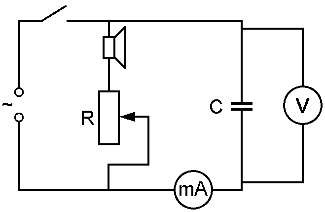
Figure 2
A variable resistor, connected in series with the loudspeaker, is used to adjust the volume of the sound.
Set the frequency on the oscillator 20 Hz and close to the maximum level of the output signal. Close the key and pay attention of the students to the readings of the measuring devices. Ask students to calculate the resistance of the capacitor based on the experimental data. Gradually increase the frequency of the generator, while demonstrating the growth of the current flowing through the capacitor with practically unchanged voltage at its terminals, and changing the frequency of the speaker sound. Watch for the digital milliammeter readings and, as soon as the current in the circuit exceeds 900 mA , stop increasing the output frequency of the generator. Inform students about the approximate frequency of the generator and ask them to determine the resistance of the capacitor again. Compare the resistance values obtained by the students and, taking into account the nature of the current change during the experiment, draw a conclusion about the inverse relationship of the capacitive resistance to the frequency of the alternating voltage.
In order to show the dependence of the capacitive resistance on the capacitance of the capacitor, close the key and once again demonstrate the operating mode of the electrical circuit obtained at the end of the previous experiment. Then replace the capacitor 18.8 uF capacitor capacitance 4.7 uF . The current in the circuit will then drop by a factor of 4, which, if the applied voltage is unchanged, means that the resistance of the capacitor has increased 4-fold. Note to students that the capacitance of capacitors 18.8 uF and 4.7 uF also differ by 4 times and draw a conclusion about inversely proportional dependence of capacitive resistance on frequency.

Figure 3
At the conclusion of this experiment, it is useful to study with students what happens in an electrical circuit containing a series-connected lamp and a capacitor (Figure 1) with a change in the frequency of the voltage applied to it. To do this, include a digital milliammeter (figure 3) in this circuit and prepare a digital voltmeter to measure the voltage across the various elements. The capacitor must be connected to the circuit in 18.8 uF
.
The resistance of the filament of a lamp depends essentially on the strength of the current flowing through it. If the lamp burns in full heat, then its resistance is 14 Ohm , but this value can become 10 times smaller with decreasing current flowing through it. In this experiment, at low frequencies, the resistance of the capacitor is large, the current in the circuit is small, the resistance of the lamp is several Om and practically all the voltage applied to the circuit is applied to the capacitor. In the high-frequency region, the resistance of the capacitor decreases to several tenths of a fraction Ohm , and all the stress exerted by the applied to the lamp, the resistance of which becomes more 10 Ohm . Thus, when the oscillator frequency changes from 30 Hz before 5 kHz the resistance of the capacitor decreases by more than 100 times, and the resistance of the lamp increases by about 10 times.
Close the key and show the students how the voltage drops on the capacitor and the lamp change as the frequency increases from 30 Hz before 5 kHz . Make appropriate comments and explain why, starting from a certain frequency value, the current in the circuit remains practically unchanged.
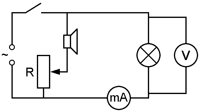
Figure 4
You can also demonstrate to the students one more effect associated with burning the lamp in an AC circuit. Assemble the electrical circuit in which the lamp and milliammeter are connected in series (Figure 4). Set the oscillator frequency 5 kHz
and the signal level corresponding to the normal burning mode of the lamp. After that smoothly reduce the frequency of the output signal of the generator, demonstrating the constancy of the current in the assembled electrical circuit and the voltage on the lamp, as well as the invariability of the lamp's glow up to the frequency 30 Hz
. At a frequency of less than 20 Hz
the change in the brightness of the lamp becomes noticeable during each oscillation period in accordance with the change in the magnitude of the voltage applied to the circuit. Note that the readings of a digital voltmeter and an ammeter in this frequency range may not be correct, since the operating range of the instruments used starts from 15Hz
.
Reactive power is a quantity characterizing the loads created by various oscillations of electromagnetic fields that occur in circuits with capacitors and inductances. And in its essence it is the energy that passes from the power source to the consumer (load), and then goes back by these reactive components during one half-cycle.
There are consumers of electrical energy, which create a purely active load. These include various heating elements, teens, incandescent lamps, and the like. These consumers are not able to generate significant electromagnetic fields. But other consumers are able to generate a reactive load. Ie create strong electromagnetic fields. The main representatives of this group can be considered devices having in their supply circuits capacitors and coils inductance. As we already know, and in different ways affect the amount of reactive power appearing in the electrical circuit.
So if we apply current and voltage to the inductor with zero phase shift, then at the output of the circuit we will see the current lag behind the voltage. But if you apply the same to the capacitor, then at the output we will get ahead of the current with voltage. For an understanding of the process, see the figure, which schematically shows the current advance of the voltage in the capacitive nature of the load.
These properties of reactive loads are used to adjust the level of voltage in the network by compensating for large inductance capacitive loads, and vice versa large capacitance - inductance.
reactive power is calculated by the following formulas:
Where, x -, I and U - current and voltage flowing in the circuit, sinφ - reactive power factor
The unit of measurement of reactive power according to SI, is the volt-ampere reactive - VAR
The nature of losses in electrical circuits with reactive components can be seen from the graphs in the figures below:
.
If there is no active component in the load, the phase shift between current and voltage will be 90 °. At the initial time, when the voltage level is maximum, the current will tend to zero, therefore, the instantaneous power value UI at this time will be zero. During the first ¼ period, the power can be visualized on the graph as a product UI (current and voltage), which becomes zero at the current maximum and zero voltage value.
In the next ¼ period, UI will lie in the negative coordinate area, therefore, the power will go back to the power source. The same will happen in the negative current half-cycle. As a result, the average (active) power consumption P avg for the period will be zero.
In this case, the reactive power, in accordance with the formula above, tends to zero. The power consumption is equal to the product of the current and voltage, the total power will be equal only to the active power. The power factor will be unity ( P / S = 1).
Consider the case of equality of reactive and active resistances in the load, ie the phase shift between current and voltage by 45 °.
In this case: Q = U × I × sin45 ° = 0.71 × U × I. Power Factor = 0.71
As you probably noticed, reactive power has usually a negative impact, in connection with which, its compensation is necessary.