In this article, we consider a DC generator and its application in various fields. The generator is, more simply, the "creator" of energy, which is subsequently used in devices designed to convert this energy in the final analysis to the benefit of man. And what is the use for us of this generator? And where, in fact, it is used, and for what?
Benefit from the generator
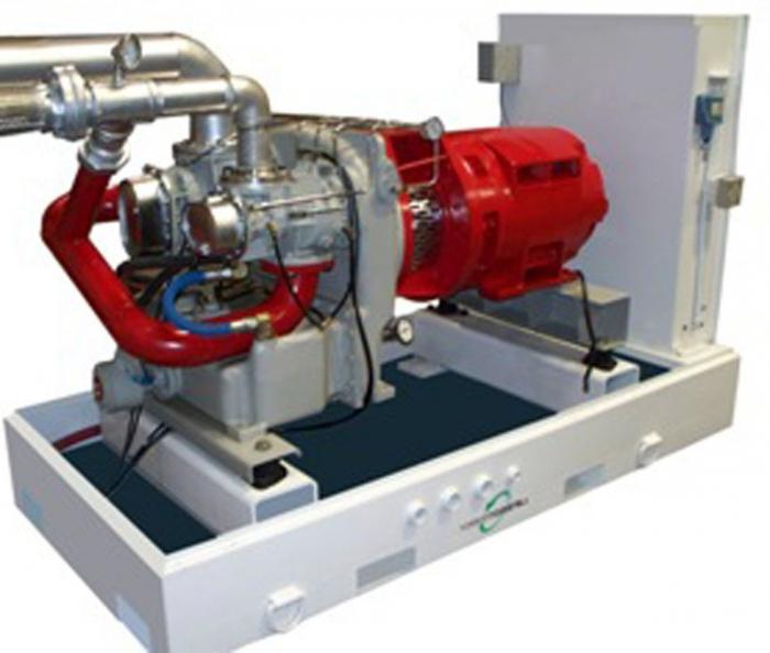
Its main application can be in factories, factories, in the construction of objects. DC power is also used in power plants and even on ships. The DC generator is in demand, and its application is increasing, only because its power, unlike the variable type, is larger for identical overall dimensions. And the most important thing is the high reliability of its simple scheme, which allows to work much longer and significantly increases the service life.
Device
There are a lot of types of this device, but the principle is always the same. That's just the way the DC generator operates. First we compare it with a variable-type generator to understand what they are different from. The DC generator has a rotor with a drum type design. And the inductor mounting is in the stator, which is stationary and made of cast iron or steel. True, steel is cast in rare cases, because this alloy is intended for metallurgical plants with a narrow profile. 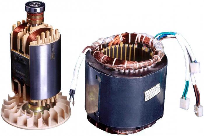 Inside the stator there are special fasteners on which wires from the copper alloy are wound, from which we get a magnetic field. In principle, there are few differences, but to obtain a direct current, without rectifiers, this type is much more efficient than a device of a variable type. The DC generator has the most common model, called the collector, which, unlike the variable type, has separate rings. They are joined to the ends of the winding of the generator armature. These separate rings have insulation between themselves and are on the common cylinder, that is, they rotate on a common axis, and brushes made of copper-graphite-based alloy are pressed on them. And actually, from these brushes the direct current in an external chain is deduced.
Welding Generator
Mainly direct current is used in welding machines. A DC welding generator is most often used in places where there is no electric alternating current.
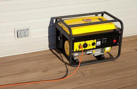
There are device and AC data. But as practice shows, they are less used because of the less versatility for powering the welding arc. As a fuel for a welding constant generator can serve as a diesel or gasoline. Gasoline are more compact and therefore it is convenient to use them in the household or on the plot.
Let's analyze principle of operation of a direct current generator, get acquainted with its design features and the principle of action.
Works based on the use of the law of electromagnetic induction. According to this law, in the conductor, which moves in a magnetic field and crosses the magnetic flux, EMF is induced.
The magnetic circuit that closes the magnetic flux is one of the main parts of the generator direct current.
Magnetic alternator circuit (depicted in Figure 1) consists of a fixed part - a stator (1) and a rotating part - a rotor (4).
The stator is a steel casing to which the remaining parts of the machine are attached, including the magnetic poles (2). The excitation winding (3) is mounted on the magnetic poles, which is fed by a direct current and creates the main magnetic flux Ф0.
Magnetic circuit of a constant-current generator with four poles.
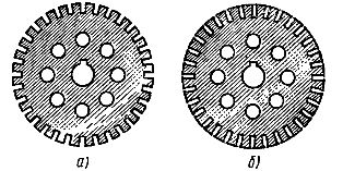
Sheets from which the magnetic circuit of the rotor is assembled: a - with open grooves, b - with half-closed grooves
The rotor of the machine is assembled from stamped steel sheets with grooves along the circumference and with holes for the shaft and ventilation. Working winding of the generator of a direct current is inserted into the grooves of the rotor (5 in figure 1). This winding is induced by the EMF by the main magnetic flux. The winding is also called armature winding, so rotor of a direct current generator it is called an anchor.
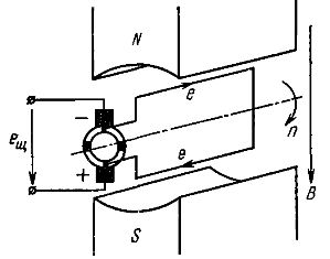
The value of the emf of the direct current generator can vary, but its polarity remains constant. The operating principle of the DC generator is shown in Fig. 3.
The magnetic flux is created by the poles of a permanent magnet. Let us assume that the armature winding consists of one turn, at which the ends are connected to different semirings, which are isolated from each other. From these semirings a collector is formed, making rotations along with the winding of the armature winding. At the same time, stationary brushes move along the collector.
When the coil rotates in a magnetic field, EMF is induced in it: e = B * l * v
- where B is the magnetic induction, l is the length of the conductor, v is its linear velocity.
When the plane of the coil coincides with the plane of the axial line of the poles (the coil is located vertically), the conductors cross the maximum magnetic flux. At this time, the maximum emf is induced in them. In the case where the coil assumes a horizontal position, the EMF in the conductors is zero.
In the conductor, the direction of the EMF is determined by the rule of the right hand (in Figure 3 it is shown in the form of arrows). When the conductor passes under the other pole during rotation, the direction of the EMF in it changes to the opposite. But as the collector rotates together with the turn, and the brushes are fixed, a conductor is always attached to the upper brush, which is located under the north pole, whose EMF is directed from the brush. As a result, the polarity of the brushes remains unchanged, and therefore remains unchanged in the direction of the emf on the brushes - e (Figure 4).
The simplest direct current generatora.
Change in time EMF of the simplest generator of a direct current.
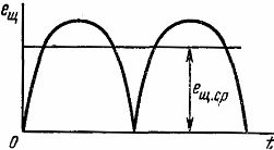
Despite the fact that the emf the simplest generator of a direct current is constant in the direction, in its value it changes. Since for one turn of the turn the EMF takes 2 times the value equal to zero and 2 times the maximum. For most DC receivers, EMF with such a large pulsation is unsuitable and, strictly speaking, it can not be called constant.
To reduce pulsation, the winding of the DC generator armature is made from a large number of turns (coils), and the collector from a large number of collector plates that are isolated from each other.
In order to consider in more detail the process of smoothing pulsations, let us take as an example the winding of the annular armature (Figure 5). It consists of four coils (1, 2, 3, 4), two turns each. The anchor moves clockwise at a frequency of n and in armature winding conductors, which are located on the outside of the armature, is induced by the EMF (the direction of motion is indicated by arrows).
The armature winding is a closed circuit, which consists of serially connected turns. In this case, the winding of the armature relative to the brushes represents two parallel branches. In Figure 5a, one parallel branch consists of a coil 2, the second of coil 4 (in coils 1 and 3 of EMF is not induced, and they are connected to both ends by one brush). In Figure 5b, the anchor is shown in a position that it occupies in 1/8 turn. In this position, one parallel branch of the armature winding consists of series-connected coils 1 and 2, and the second of the series-connected coils 3 and 4.
The scheme of the simplest generator of a direct current with a ring armature.
![]()
When the armature rotates with respect to the brushes, each coil has a constant polarity.
Figure 6a shows how, as the armature rotates, the EMF of the coils changes with time. Emf on the brushes is equal to the emf of each of the parallel branches of the armature winding.
It can be seen from figure 5 that the EMF of the parallel branch is equal to either the sum of the EMF of two adjacent coils or the EMF of one coil:
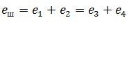
As a result of this, the pulsations of the EMF winding of the armature decrease noticeably (Fig. 6b). This means that by increasing the number of turns and collector plates it is possible to obtain a practically constant EMF winding of the armature.
The time variation of the EMF of the coils and the winding of the annular armature.
The principle of the DC generator is based on the emergence of EMF in a frame rotating in a magnetic field (Fig. 6-1, a). For one turn in each working (active) part of the frame, the EMF changes its sign twice. In order for the current in the external circuit to have only one direction (constant), a collector is used - two half rings connected to the ends of the frame, and the frame is connected to the external circuit through a rotating collector and stationary brushes. As soon as the active side of the frame begins to cross the lines of magnetic induction in the opposite direction as compared with
previous, connected to this side of the semiring of the collector will come into contact with another brush. Thanks to such a device, the current direction in the external circuit remains unchanged, although its value changes (pulsates, Fig. 6-1, b).
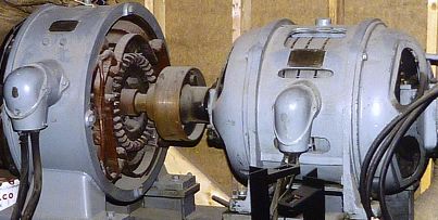
The device of the industrial DC generator is shown in Figure 6-2. On the inner surface of the frame made of solid cast iron, the main poles 2 with excitation windings and additional poles with windings are tightly fixed to compensate for the emf of self-induction and the reaction of the armature. In most cases, the electromagnets are powered by the generator itself. Inside the frame is placed an anchor 3, which is a metal cylinder, recruited from the stamped plates of electrical steel. In the longitudinal grooves on the armature surface, the armature winding is composed of interconnected sections. To smooth out the EMF pulsations and current winding
![]()
anchor is evenly distributed over the entire surface, the magnetic resistance between the poles is reduced due to the steel core of the armature. The leads of the windings are soldered to the copper plates of the collector 4 isolated from each other and from the body of the machine, the end of one section and the beginning of the next section being soldered to the same plate. The collector is rigidly fixed to the armature shaft, and a fan is mounted on the same shaft. The armature shaft is placed in the bearings of the bearing shields 5, which are fixed on the sides of the frame. An insignificant air gap forms between the anchor and poles of the stator, due to which the armature can freely rotate. On the cylindrical surface of the collector, carbon brushes inserted into the brush holders 6 are applied. To reduce the resistance of the brush, they are often pressed from a mixture of coal and copper powder.
DC machines are often made multi-pole (Figure 6-3), while in each section of the winding in one revolution the value and sign of the EMF change as many times as many poles. The magnetic circuit of such a machine is more complex, the number of pairs of brushes being equal to the number of pairs of poles, and the brushes of the same polarity are connected together.
The principles of the DC generator are discussed in more detail.
If the anchor is made in the form of a ring and on it to place the winding in the form of a closed toroid, then such an anchor is called annular, and the winding is called a spiral. When this armature rotates in a magnetic field, EMF will be induced in the windings of its winding (Fig. 6-4, a). It turns out that in the windings of one half of the winding the EMF has one sign, in the turns of the other half - the opposite. If the turns are evenly distributed over the surface of the armature, then there will be no current in the winding, since the action of the EMF of both halves is mutually compensated. If, for example, the insulation is partially removed from the outer side, and two fixed brushes (a and b) are applied on two opposite sides so that when the anchor rotates they can touch each turn, it is easy to see that the entire winding will be divided in half and with the rotation of the winding armature, one half of the winding will gradually change to another, while the number of turns of each half, the polarity and the EMF value will remain unchanged. If you now connect the load to the brushes, a constant current is established in the external circuit and in each half of the winding.
Obviously, for a more complete use of the EMF winding brush should be connected in those points where the EMF is not induced. A straight line passing through two such points is called a geometric neutral (GN). With this arrangement of the brushes, the winding is divided into two parallel branches, connected together and external circuit by brushes. If the brushes are displaced with respect to the geometric neutral, in the part of the turns of each parallel branch, the EMF will have opposite polarity, and under the brushes sparks can start, since in the shorted turns (sections) the EMF is non-zero.
The annular anchor can be improved if you do not remove the insulation from the turns of the winding, but make from them the bends connected to the collector plates, and put the brushes on the collector (Fig. 6-4, b). If this machine has four poles, the winding will be divided into four parts (Figure 6-5, a). If we now put four instead of two brushes and connect them with the same name (Figures 6-5, b), then the winding will have four parallel branches. It is easy to see that as the number of parallel branches increases, the load current can be increased accordingly.
The annular anchor with spiral winding considered above has significant drawbacks. First, the magnetic flux closes through the wall of the ring (armature), bypassing the internal cavity, so the active side of each coil winding is one that is located on the surface, and the inner part of the turn to produce EMF is not used and serves only as a connecting conductor. This circumstance leads to an unreasonable consumption of copper. Secondly, the spiral winding can not be made on a pattern, so at the present time machines with a ring anchor are not manufactured.
Disadvantages of the annular anchor are eliminated by replacing it with a drum. The windings of the drum armature (Figures 6-6) are placed in special grooves on the surface of the cylinder (anchor) in the form of separate sections, connected in certain way to the collector plates and to each other. The section is part of the winding between two adjacent taps to the manifold. Both sides of each section are active; sections are made by template.
Bookmark this site
An annular anchor with a spiral winding is not currently used, since with a spiral winding of more than half its length it does not participate in the formation of EDE, but serves only to connect active conductors lying on the outside of the annular armature.
Much better is used copper in the windings of a relatively complex drum-type anchor. The drum anchor is a cylinder assembled from sheets of electrical steel, in the grooves of which only conductors of the armature winding are placed on the outside of the drum.
The DC machine is reversible: if the machine rotates the primary motor and the magnetic field of the machine is energized, then the EMF is induced in the armature and the machine sends a direct current to the external circuit through the collector and brushes. In the armature, this current, interacting with the field of the machine, creates a braking torque overcome by the primary engine. In such conditions, the machine operates as a generator.
If, on the other hand, the armature and excitation winding of the machine are switched on under a constant voltage, the current passing through the armature winding interacting with the field of the machine creates a torque that causes the armature to rotate, while an anti-EMF is induced in the armature winding. In such conditions, the machine operates in the engine mode, turning electrical energy into a mechanical one.