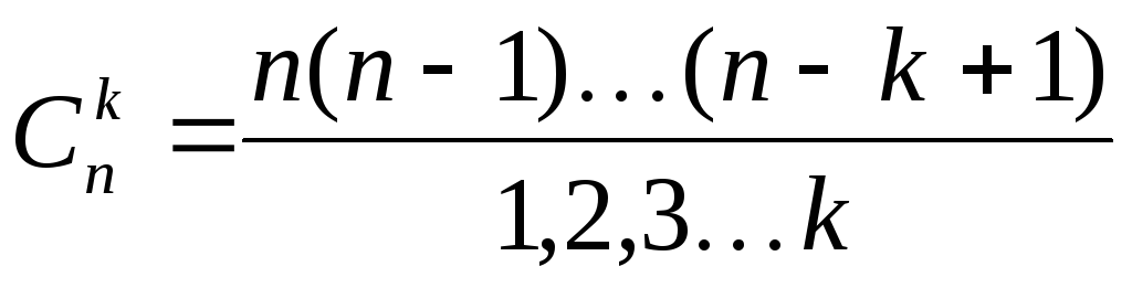
1. Determine the A-parameters of the four-terminal network.
2. Perform a verification of the basic relationship between them.
3. Determine the secondary parameters of the four-terminal network (input and output characteristic impedances and the transmission constant of the four-terminal network).
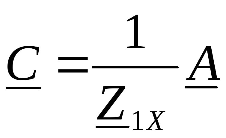
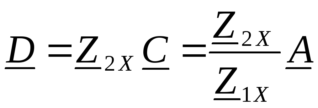
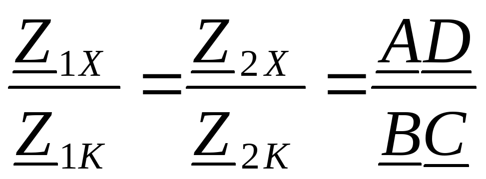
4. Determine the input, output characteristic impedances and the transmission constant of two cascade-connected matching four-ports.
5. Derive the formulas of amplitude-frequency (AFC) and phase-frequency (PFC) characteristics.
6. Using one of the application programs (Electronic Bench WEWB, MATHCAD or other), obtain the frequency response curves and PFC and add them to the explanatory note.
7. Determine the transient and impulse response of a four-terminal network using classical and operator methods.
Date of issue of the assignment: «» ______________ 20 ___ years
Date of completion of the project: «» _______________20___ year
The assignment was accepted for execution: / _________________ /
Head of the course project: Associate Professor Gorbunova NG / _________________ /
| LIT. |
| Sheets |
| 23018 HI |
| 1. Task for course design | |
| 2. Introduction | |
| 3. Determination of the A-parameters of the four-terminal network. | |
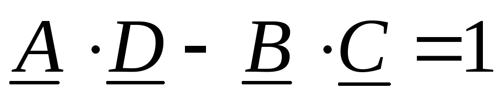
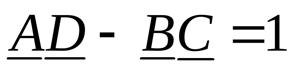
| 4. Testing of A-parameters | |
| 5. Determination of the secondary parameters of the four-terminal network (input and output characteristic impedances and the transmission constant of the four-terminal network) | |
| 6. Calculation of the operational transmission of a four-terminal network | |
| 7. Derivation of the formulas for frequency response and phase response | |
| 8. Graphs of frequency response and phase response | |
| 9. Determination of the transient and impulse response of the four-terminal network 10. Calculation of the circuit in the form of voltage on the capacitor when applying a single voltage to the input | |
| 11. Conclusion | |
| 12. List of used literature | |
| 13. Annexes |
| Rev. |
| Sheet |
| № of documents. |
| Signature |
| date |
| Sheet |
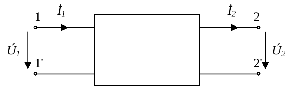
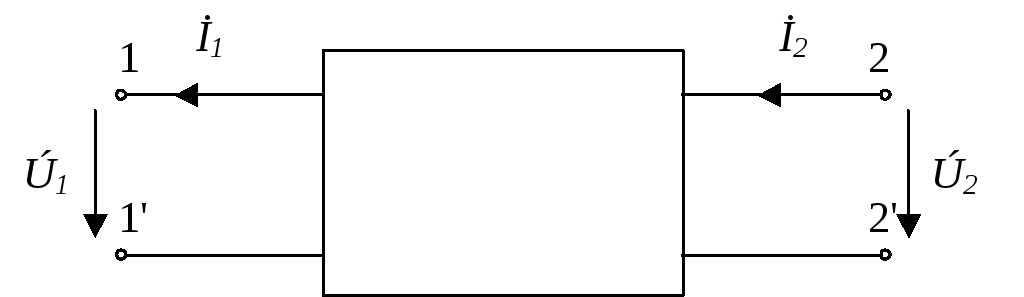
In the communication technique, a four-terminal network is understood as an electrical circuit (or part thereof) of any complexity, having two pairs of terminals for connecting to a source and a receiver of electrical energy. The terminals to which the source is connected are called input terminals, and the terminals to which the receiver (load) is attached, are the output terminals (poles).
The proposed course work contains a task for calculating the parameters of passive four-ports. The student is given an individual printout with a circuit and digital data, on the basis of which the A-parameters of the four-terminal network are determined, their verification is performed, the secondary parameters of the four-terminal network (input and output characteristic impedance and constant transmission of the four-terminal network) are determined, input, output characteristic impedances and the transmission constant of the two cascaded connected harmonized four-ports, the formula of the amplitude-frequency (AFC) and phase-frequency (PFC) char line providers. Using one of the application programs (electronic bench WEWB, MATHCAD or another), you need to obtain the curves of frequency response and phase response and add them to the explanatory note. The transient and impulse response of the four-terminal network is determined using classical and operator methods.
| Rev. |
| Sheet |
| № of documents. |
| Signature |
| date |
| Sheet |
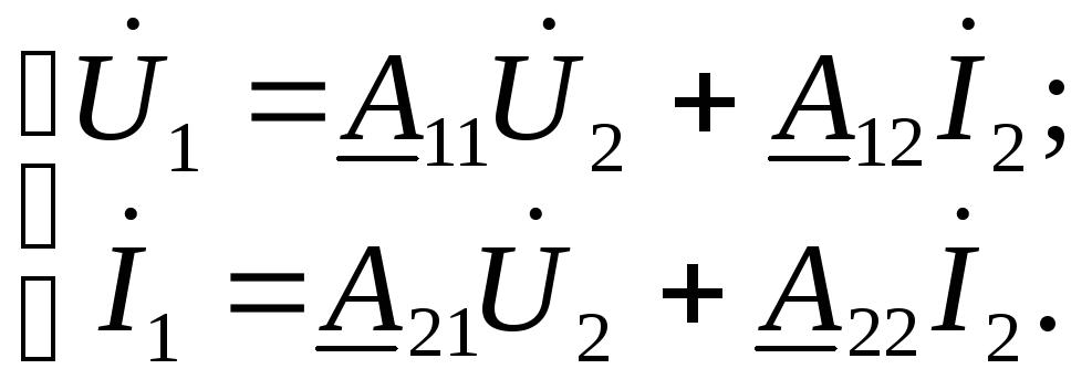
Determine the A-parameters of the four-terminal network
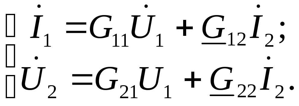
Analytic ratios of currents and voltages at the input and output of a four-terminal network are called transmission equations for a four-terminal network. The quantities connecting the currents and voltages in these equations are called the parameters of the four-terminal network.
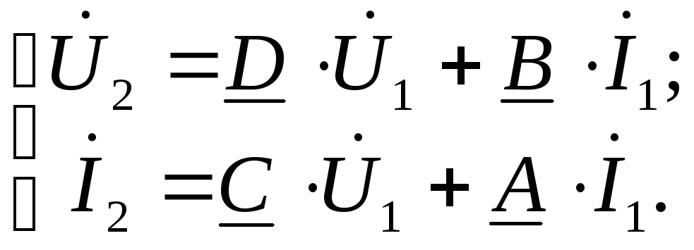
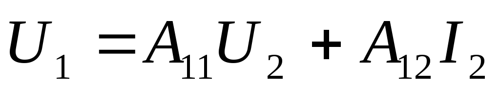
In the system of equations with A-parameters, the current and voltage at the input terminals are determined through the current and voltage at the output terminals.
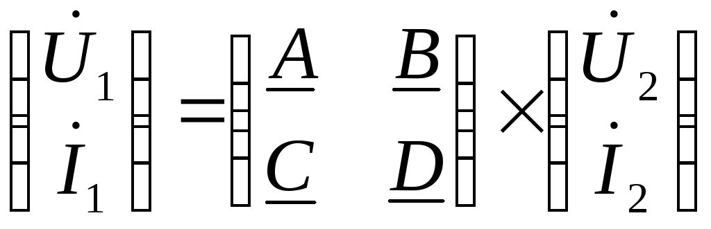
We write down the A-parameter equations for the four-terminal network:
| (1.1) | ||
The A parameters have the following physical meaning: - the inverse of the voltage transmission ratio, - the resistance at the input terminals of the four-terminal network, - the conductivity at the output terminals of the four-terminal network, - the inverse of the current transmission coefficient.
BASIC CONCEPTS
Four-terminal network- part of the electrical circuit, which has two input and two output terminals (transformer, power line, filter, electronic amplifier).
The term "four-terminal network" is used when it is necessary to know the currents and voltages at the input and output of an electrical device and there is no need to know the currents and voltages inside this device.
Passive four-terminal network- the four-terminal network does not contain an energy source ( active- contains).
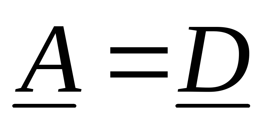
Symmetrical four-terminal network- changing the places of its input and output terminals does not change the input and output voltages and currents.
6.1.1. Four-terminal network equations
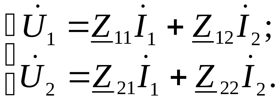
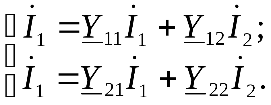
The relationship between voltages and currents at the input and output of a four-terminal network ( Ú 1 , İ 1 , Ú 2 , İ 2 ) is expressed by means of two quadripole equations in which two others are found for two given values.
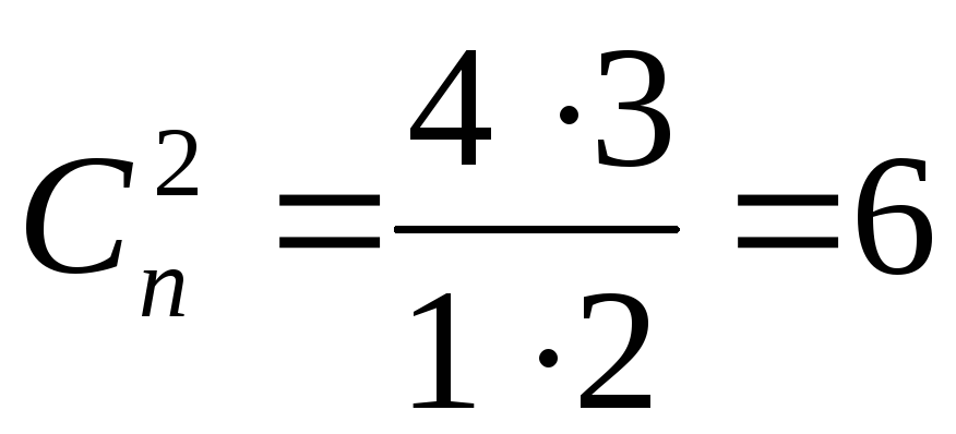
In total, you can write six different in form, but essentially equivalent systems of equations (the number of combinations of four to two).
 ,
, .
.
These equations correspond to certain conditionally positive directions of currents and voltages in the input and output circuits of the four-terminal network.
Parameters (coefficients) of the four-terminal network (  ) depend on the structure (scheme of internal connections) of the four-terminal network, the values of the resistances of the elements making up the four-terminal network, and in general represent complex numbers.
For each four-terminal network, these coefficients can be determined by calculation or by experimental means.
 - type (form) A;
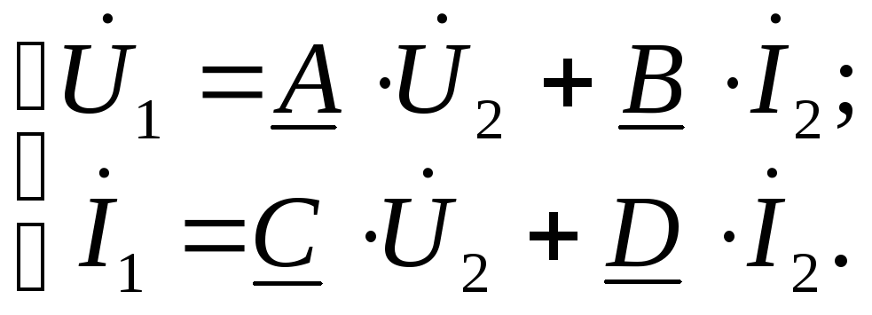 Basic equation of the four-terminal network.
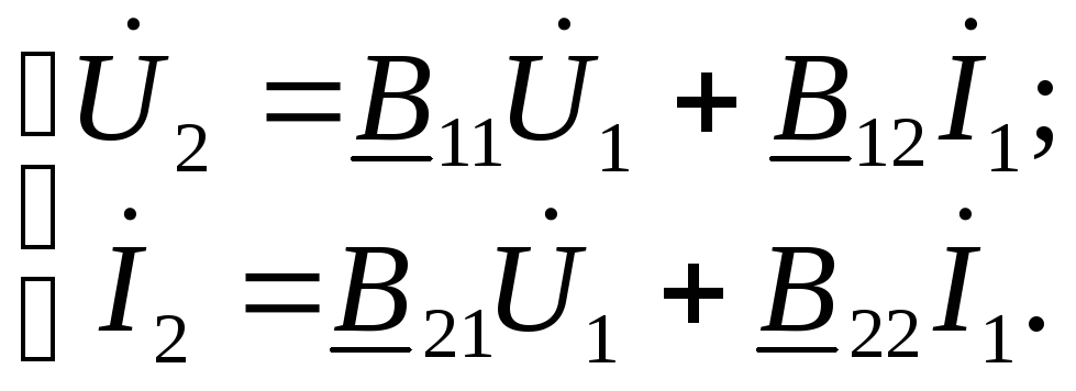 - type B;
Equations of the relation between the coefficients
 .
.

 -Z- shape. The equation of connection
 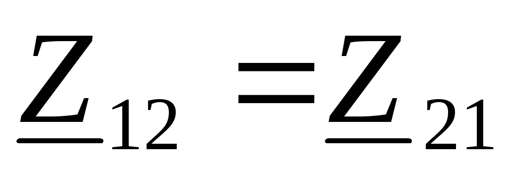 .
.
 -Y- shape. The equation of connection
 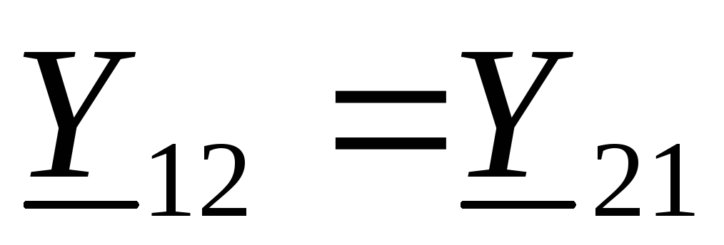 .
.
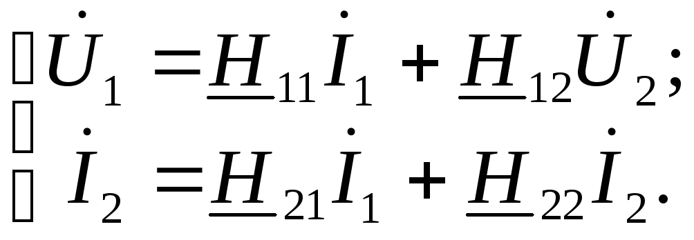 -H- form. The equation of connection
 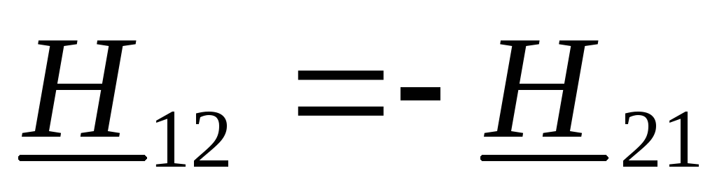 .
.
 -G- form. The equation of connection
 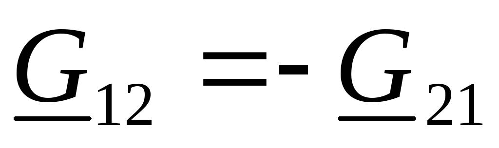 .
.
The coefficients of the four-terminal network for various forms of recording are related to each other by relations that allow one to pass from one form of writing equations to another.These relationships are given in the reference books. Therefore, it is sufficient to set the coefficients and other dependencies for one form of the record, and then you can get all the necessary quantities for any other form of recording.
In what follows we shall consider all the necessary relations for the A-form of writing the equations.
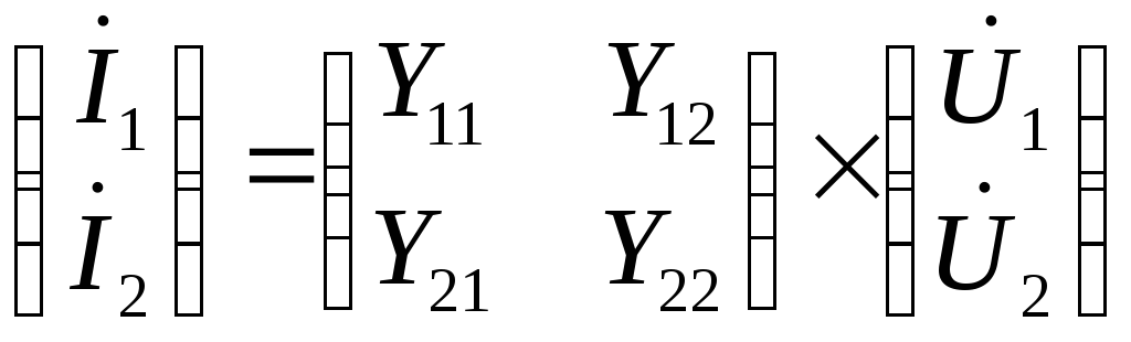
To write the quadripole equations, a matrix form of recording is widely used. This is especially convenient and effective in the study of the operation modes of several four-ports, connected by one way or another (cascaded, sequential, parallel, etc.).
 or
or 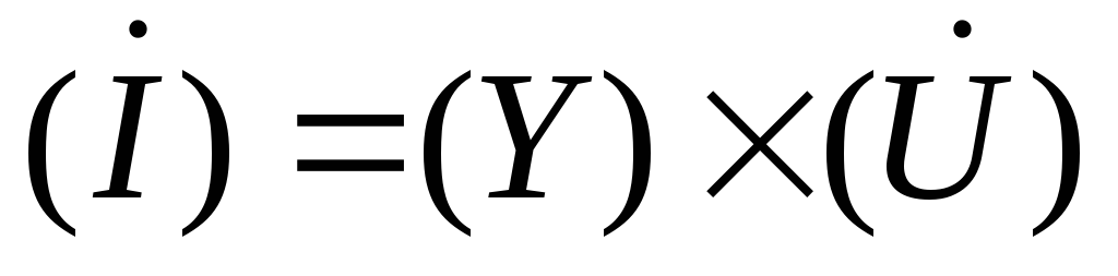 ;
;
 or
or 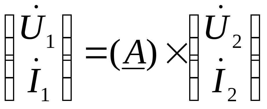 .
.
6.1.2. Four-terminal network coefficients
The four-terminal network is given if its coefficients are known.
Almost for calculating the coefficients, the values of the input impedances of the four-terminal network are used in the mode of short-circuit and short-circuit.
The resistance of the XX and short-circuit can either be measured with a measuring bridge or an ammeter, a voltmeter, a wattmeter and a phase meter, initially included on the input side, and then on the output side (the reverse of the CT and XX) ,
or calculated according to a known four-terminal network .
Then,  and
and  determine coefficients by known formulas.
Input impedances
From the entrance
 .
.
Since the release
 .
.
For a symmetric four-terminal network
 ,
, .
.
At the XX
 ;
;
 ,
, .
.
With a fault
 ;
;
 ,
, .
.
 ;
; ;
; ;
; .
.
It is easy to show that
 ;
; .
.
Taking into account the coupling equation to calculate 4 coefficients, only 3 input impedances must be determined.
For a symmetric four-terminal network , and therefore it is sufficient to know only two input impedances (  ,
, ).
).
 ;
; ;
; ;;
;; ;
;
 .
.
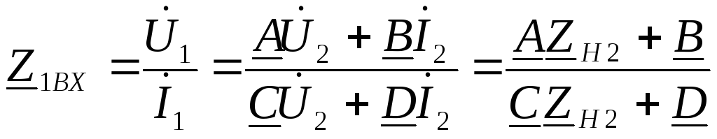
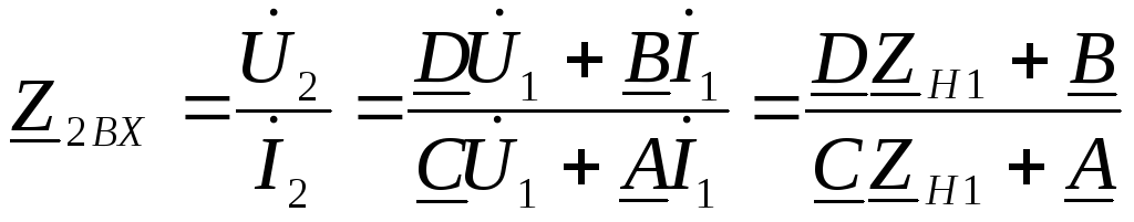
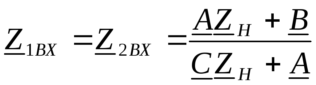
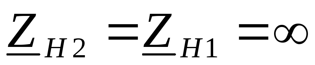
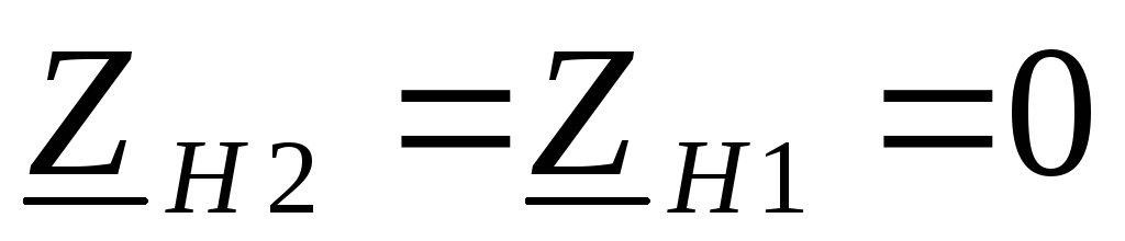
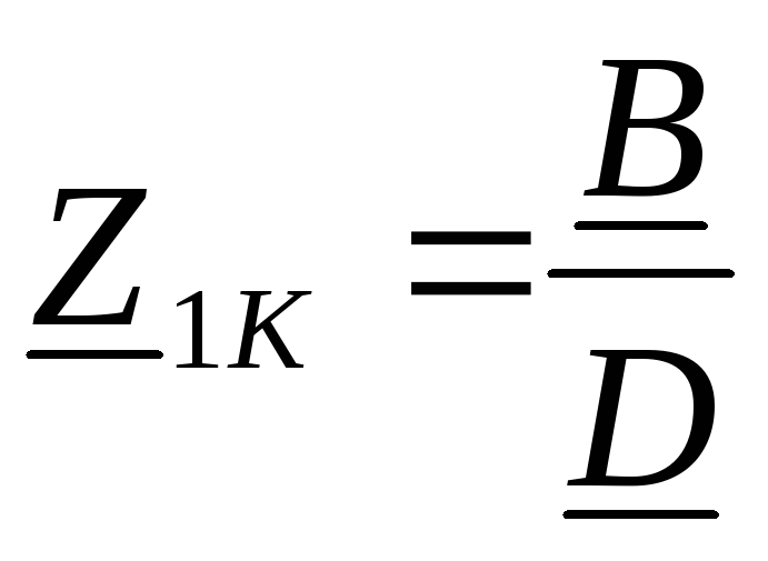
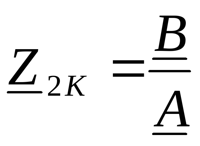
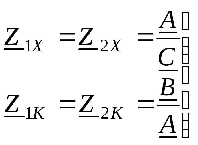
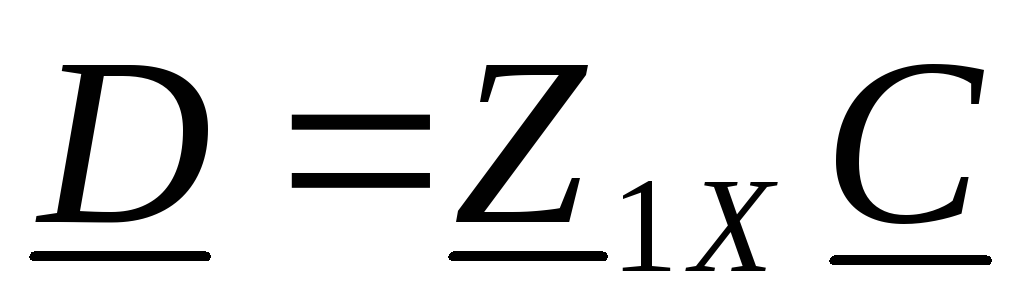
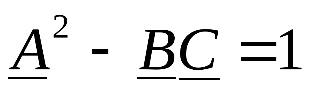
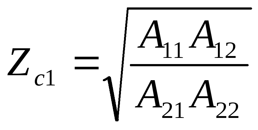
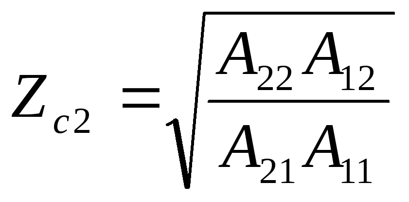
The resistance included in the input circuit of the four-terminal network Zc1 = Zr = Zвх, and the resistance included in its output circuit Zc1 = Zн = Zvy, providing a regime of consistent inclusion on both pairs of its terminals, are called respectively input and output characteristic impedances of the four-terminal network .
The connection of all four-poles of the chain circuit under the conditions of matching is called a characteristically compatible compound.
The following definition is also true.
Characteristic resistances a four-terminal network is called a pair of resistancesZc1 andZc2 , which are selected in such a way that when connected to the terminals 2-2 'of resistanceZmr.2 = Zc2 input resistance of the four-terminal network on the side of the resistance 1-1 'Zmr.1 = Zc1 the input resistance of the four-terminal network on the side of the clamps 2-2 'is equal toZc2 .
Fig. 9.9 - Determination of characteristic resistances
four-terminal network
The resistance Zc1 is called characteristic input, and Zc2 - characteristic output resistance of a four-terminal network.
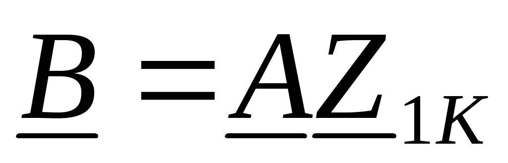
We express them in terms of A-parameters. The matching at the input occurs at Zr = Zin = Zc1, and at the output - at Zn = Zout = Zc2. Using the expressions for the input and output impedances of the loaded four-terminal network (9.27) and (9.30), we write these conditions in the form:
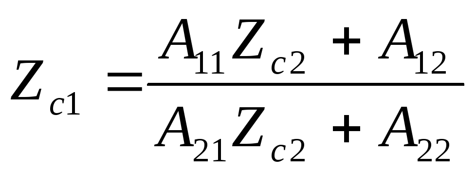
We present the relations obtained to the system:
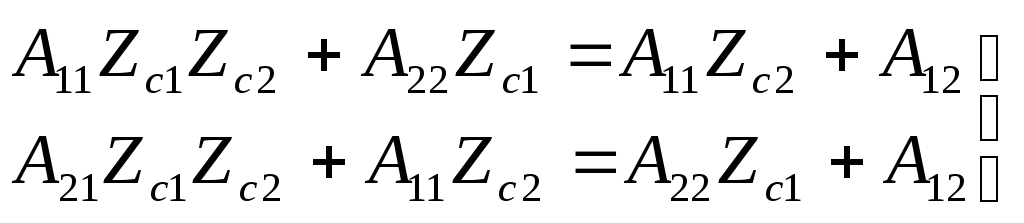
Solving these equations together, we obtain the values of the characteristic resistances:
 (9.32)
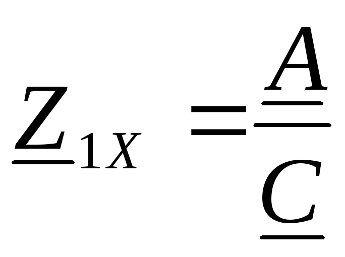
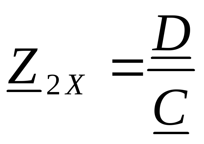
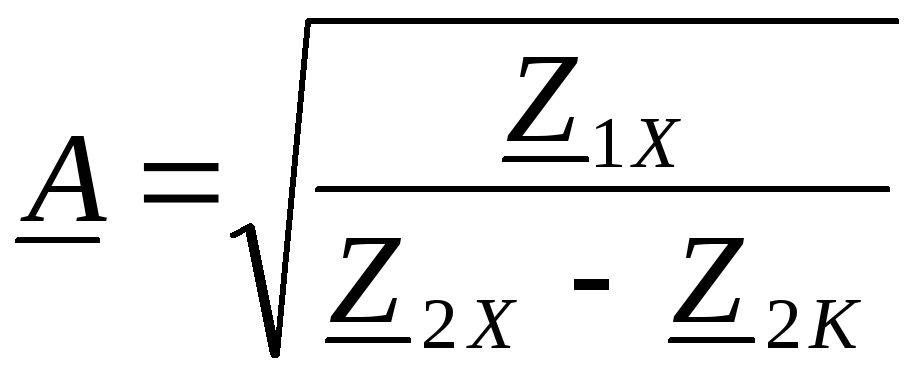
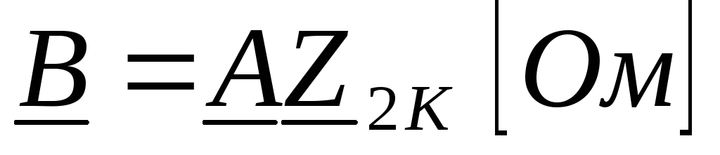
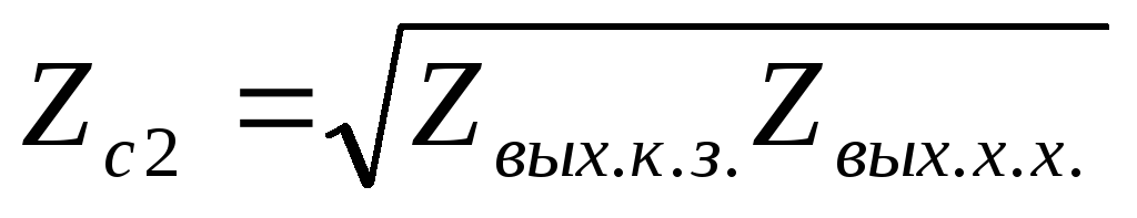
The characteristic impedances of the four-terminal network can be determined using expressions (9.28) and (9.30):
![]()
 (9.33)
Consequently, characteristic input impedance equal to the geometric mean of the input impedances in the case of a short circuit and an idling, the output characteristic impedance is equal to the geometric mean of the output resistances in the case of a short circuit and an idling.
Expressions (9.33) make it possible to determine the characteristic resistances from the experiments of idling and short circuit.
5.4. Measurement of transmission of a four-terminal network
The obtained parameters Zc1 and Zc2 do not give a complete description of the reversible four-terminal network. As it was established earlier, such a four-terminal network is characterized by three independent parameters.
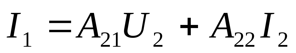
To determine the transfer coefficient of a four-terminal network with respect to the voltage Ku and the current Ki through the A-parameters.
We take the quadripole equation in the A form:

From the first equation, taking into account that 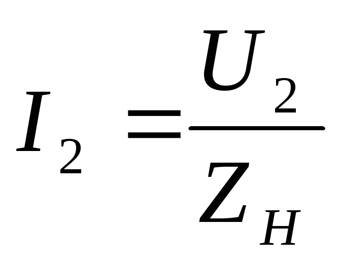 we get
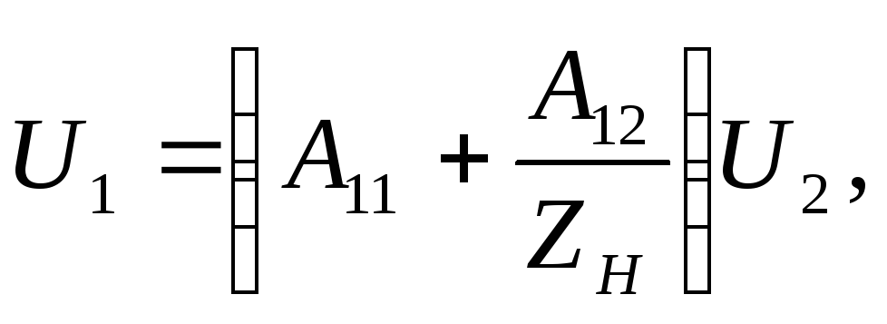
 (9.34)
Similarly, from the second quadripole equation, we find:
Location 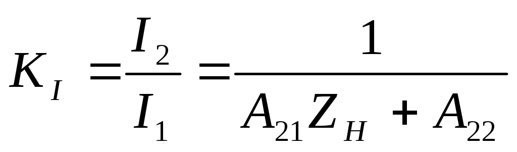 ;
;
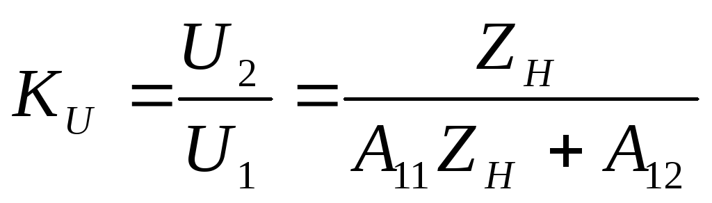
We derive expressions for the transmission coefficients for voltage and current in the matching mode, when
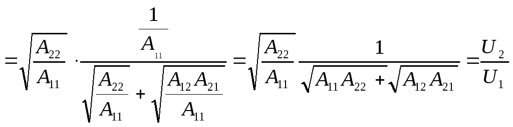 (9.35)
The third characteristic parameter of the four-terminal network is the measure of transmission of Г, which connects the currents and voltages at the input and output in the matching mode. It is determined from the relation:
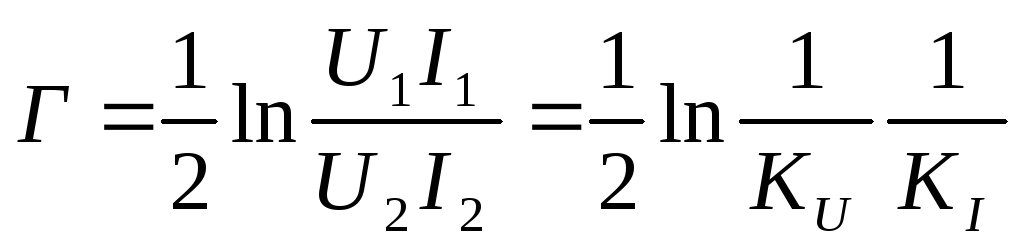 (9.37)
Using the expressions obtained for Ku and Ki, respectively (9.35) and (9.36, we obtain:
The characteristic parameters Zc1, Zc2 and Г introduced in this way completely describe the reversible four-terminal network.
The measure of transmission of a symmetrical four-terminal network makes it possible to clarify its physical meaning:
where 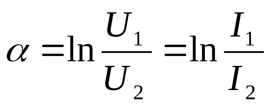 The real part of the transmission measure - attenuation coefficient
- shows on a logarithmic scale how many times the effective value of voltage and current decreases when switching from input terminals to output terminals of a four-terminal network with an agreed load;
The real part of the transmission measure - attenuation coefficient
- shows on a logarithmic scale how many times the effective value of voltage and current decreases when switching from input terminals to output terminals of a four-terminal network with an agreed load;
The imaginary part of the transmission measure - phase factor shows how much the phase of voltage and current changes when passing through a coherently tight quadrupole.
 is measured in neper (Hn). If = 1 Hn, this means that the voltage
  less voltage U 1 in
  2,718 times.
In practice, such an attenuation unit often turns out to be too large, and therefore often one more unit of attenuation measurement is used, called decibel . Wherein:
= 20ln 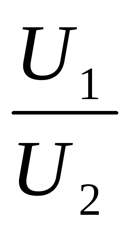 . If = 1 dB, then =
Obviously, the following equalities hold:
1 H = 8.686 dB; 1 dB = 0.115 Np.
 measured in radians (rad)