What is a capacitor? How is it arranged? Who invented the world's first capacitor? - we will disclose all these questions in detail today. So, what is this device. Many of the schools remember that capacitor -
this device is designed for accumulation and transfer of charge. It consists of two metal plates, between which there is a dielectric layer.
The history of this device began in 1745, when German physicist Ewald Jurgen von Kleist and Dutch physicist Peter van Mushenbrook accidentally created a Leyden jar. It was the first capacitor in the world. The most important thing in a capacitor is its capacitance and rated voltage.
Capacity -
this is the ability of a capacitor to accumulate an electrical charge. Capacity is measured in Farad (F). The most common values in the calculations are:
- picofarad (10 -12);
- nanofarad (10 -9);
- microfarad (10 -6).
I will give an example: the capacitance of our planet Earth is 710 mkF. In order to obtain 1 Farad, a conductor is necessary, whose potential would increase by 1V when the charge is transferred to it in 1 pendant. Those. It is clear that 1 Farad is a very large capacitance, that is why when calculating or designing, small values are often used (pF, nF, μF). By the way, here's a little crib: 1mkF = 1000nF = 1000000pkF. Condensers are found in almost any electrical device: in devices, in computers,
, in cards, etc.
And know that the capacity increases with the area of the plates and decreases with the distance between them. With capacitance, it seems everything is clear, now we will pass to the nominal voltage.
this voltage, when exceeded, breakdown of the dielectric occurs. 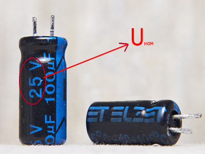 Consequently, the operation of the device will cease, because when dielectric breakdown occurs Nominal voltage depends both on the dielectric (material) and on the distance between the plates. It is also necessary to know that the rated voltage must be at least 2 times higher than that which will be applied to it during operation. In other words, if the power supply is designed for 12V, then the rated voltage of the capacitor should be at least 12 * 2 = 24V. With a nominal voltage, I hope everything is clear go further.
What do you think, what determines the charging and discharging time of the capacitor itself? You probably already guessed that from the capacity and the total resistance of the circuit. That is, the more capacitance and resistance, the more time it takes to charge. After all, if the capacitance is large, consequently the amount of the charged charge in it will be greater, and hence the time for charging and discharging will also be greater. It's like with
Well, the resistance reduces the current, and if the current is small, then it takes more time to charge.
In real life, it is necessary to remember that there is a so-called leakage current
. Not many people know that the dielectric still passes a small current between the plates. And if it passes, then eventually it leads to the loss of the original charge. Those. if the capacitor was fully charged, then after a certain period of time the charge in it will become smaller and will decrease until the next connection to the network.
Types of capacitors
We examined the main characteristics, and also learned what the charging and discharging time depends on and how the leakage current affects the capacitor charge. All capacitors vary in size and internal characteristics. Therefore, it is better to know the types of capacitors, this is useful in radio engineering, electronics ... To the left is a short notation (BM, CD, BMT, etc.), and on the right is its decoding:
BM - paper compact
BMT - paper small-sized heat-resistant
CD - ceramic disc
KLS - ceramic cast section
KM - ceramic monolithic
KPK-M - trimmer ceramic small-sized
CSR - mica-shaped
CT - ceramic tubular
MBG - metallized paper sealant
MBGO - metal-paper hermetic single-layer
MBGT is a metal-welded, heat-resistant
IBGCH - metal-paper sealed single-layer
MBM - metal small paper
PM - polystyrene small-sized
ON - film open
JI - film styroflex open
Polarized and unpolarized capacitors
At a close inspection of the hull, you can see the designation on the poles "+" and "-". Those capacitors that have such designations are called polarized, and those who do not have them - unpolarized. These symbols must be taken into account (plus to plus, minus to minus), otherwise, if the connection is incorrect, the capacitor will fail. But this notation is not available for all devices. For example, those devices with a capacitance of more than 0.5 μF are polarized, and unpolarized ones include ceramic disc and other capacitive capacitors.
The main element of losses is dielectric. If the frequency, humidity or 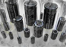 losses increase. For example, when the temperature changes, the distance between the plates changes and the properties of the capacitor, respectively, too. Minimum losses are those devices, the dielectric of which is made of high-frequency ceramics, as well as paper and ferroelectric ceramics.
Depending on the design and dielectric, the capacitors are characterized by different temperature coefficient of capacity (TKE). It shows the relative change in capacity with a temperature change of 1 ° C. And the temperature coefficient of capacity can be either positive or negative. By the value and the sign of TKE, all capacitors are divided into groups, which are assigned the letter designations and the color of the case.
Losses must be considered when replacing a damaged capacitor.
After reading this text, you learned what a capacitor is and how it is characterized. Thank you for attention)))
In the first approximation, the capacitors (Figure 1.8) are frequency-dependent resistors.
They allow you to create, for example, frequency-dependent voltage dividers. To solve some problems (shunting, linking contours), great knowledge about the condensate is not required, other tasks (the construction of filters, resonant circuits, energy storage) require more in-depth knowledge. For example, capacitors do not dissipate energy, although current flows through them, the fact is that the current and voltage on the capacitor are shifted 90 degrees relative to one another in phase.
A capacitor is a device that has two terminals and has the following property:
A capacitor having a capacitance C of Farad, to which voltage is applied Uvolts, accumulates a charge Q pendant.
Differentiating the expression for -Q, we obtain
![]() (6)
(6)
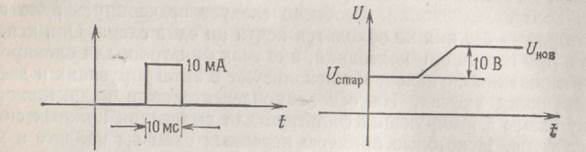
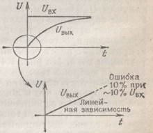
So, a capacitor is a more complex element than a resistor; The current is proportional not only to the voltage, but to the rate of change of the voltage. If the voltage across the capacitor having a capacitance of 1Φ changes by 1 V per 1 s, we get a current of 1 A. Conversely, a current of 1 A through a 1-F capacitor causes a voltage change of 1 V per 1 s. A capacitance equal to one Farad is very large, and therefore more often deal with microfarads (μF) or picofarads (pF). (To mislead the uninitiated, the designations of the units of measurement are sometimes omitted from the schematic diagrams, they have to be guessed from the context.) For example, if a 1 mA current is applied to a 1 μF capacitor, then the voltage for 1 s increases by 1000 V. The current pulse duration of 10 ms will cause an increase in voltage on the capacitor by 10 V (Figure 1.9).
The industry produces capacitors of various shapes and sizes; After a while you will get to know the most common representatives of this vast family. The simplest capacitor consists of two conductors located a short distance from each other (but not in contact with each other); the present simplest capacitors have exactly this design. To get a large capacity, you need a large area and a smaller gap between the conductors; usually one of the conductors is covered with a thin layer of insulating material (called a dielectric), for such capacitors, for example, an aluminized (aluminum-coated) mylar film is used. Widely distributed the following types of capacitors: ceramic, electrolytic (made of metal foil fromoxide film as an insulator), mica (made of metallized mica). Each type of capacitor has its own characteristics. In general, we can say that ceramic and mylar capacitors are suitable for non-critical circuits; in circuits where a large capacity is required, tantalum capacitors are used, and electrolytic capacitors are used for filtering in power supplies.
Parallel and series connection of capacitors
The capacitance of several parallel capacitors is equal to the sum of their capacitances. It is easy to see this: apply voltage to the parallel connection, then
![]() (8)
(8)
For the serial connection of capacitors, we have the same expression as for a parallel connection of resistors:
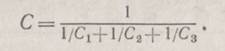 (9)
(9)
In the particular case for two capacitors
![]() (10)
(10)
§ 1.5. Changes in the time of voltage and current
RC Chains
For the analysis of AC circuits (or in the general case of circuits working with varying voltages and currents), two types of characteristics can be used. First, you can consider voltage changes U and current I in time, and secondly, the change in amplitude with a change in the frequency of the signal. Both these and other characteristics have their advantages, and in each practical case it is necessary to choose the most suitable ones. We will begin studying the AC circuits with time dependencies, and then we turn to frequency characteristics.
What are the properties of circuits, which include capacitors? In order to answer this question, let us consider the simplest RC Chain(Figure 1.10).
We use the expression for capacitance obtained earlier:
This expression is a differential equation whose solution has the form
![]() (12)
(12)
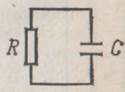
It follows that if a charged capacitor is connected to a resistor, it will be discharged as shown in Fig. 1.11.
Time constant
The product RC is called time constantchain. If Rmeasured in ohms, and C - in farads, then the product RC will be measured in seconds. For a 1 μF capacitor connected to a 1 kΩ resistor, the time constant is 1 ms; if the capacitor was pre-charged and the voltage on it is 1 V, then when the resistor is connected, a current of 1 mA will appear in the circuit. In Fig. 1.12 shows a slightly different scheme.
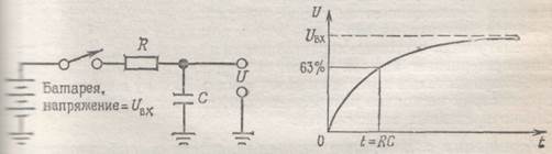
Fig. 1.12. Fig. 1.13.
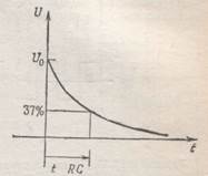
At time t = 0, the circuit is connected to the battery. The equation describing the operation of such a scheme is as follows:
and has a solution
![]() (14)
(14)
Do not be scared if you do not understand how the mathematical transformation is done. It is important to remember the result. In the future, we will repeatedly use it without resorting to mathematical calculations. Constant Ais determined from the initial conditions (Figure 1.13): U = 0 for t = 0,whence A = -U inand U = U in (1 - e - t / RC).
Establishment of equilibrium
Under the condition t \u003e\u003e RC, the voltage U reaches the value U in.(We advise you to memorize a good practical rule, called the rule of the five RC, it says: for a time equal to five time constants, the capacitor is charged or discharged by 99%). If then change the input voltage U in (making it equal, for example, to zero), then the voltage across the capacitor U will decrease , tending to a new value according to the exponential law e - t / RC.
Differential chains
Consider the circuit depicted in Fig. 1.14. Voltage on the capacitor FROMequally U in -U,so
If the resistor and capacitor are chosen so that the resistance R and capacitance FROMwere sufficiently small and the condition dU / dt <
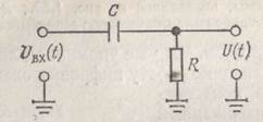
Thus, we have obtained that the output voltage is proportional to the rate of change of the input signal.
In order that condition dU / dt<
![]()
Differential chains are convenient for using frontand trailing edgespulse signals, and in digital circuits one can sometimes find chains similar to that shown in Fig. 1.16.
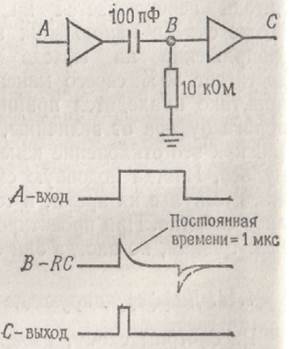
A differentiating RC circuit generates pulses in the form of short peaks at the switching times of the input signal, and the output buffer amplifier converts these pulses into short rectangular pulses. In real circuits, the negative peak is small due to the built-in diode buffer.
Sometimes the scheme unexpectedly begins to show differentiating properties, and in situations where they are absolutely undesirable. In this case, one can observe signals similar to those shown in Fig. 1.17. The first signal (more precisely, the impulse noise) can arise when there is a capacitive coupling between the line under consideration and the circuit in which a rectangular signal is present; the cause of this interference is the absence of a termination resistor in the line.
If the resistor is, then either reduce the resistance of the signal source for the line, or find a way to attenuate the capacitive coupling with the source of the signals of a rectangular shape. A signal of the second type can be observed in the circuit through which a signal of a rectangular shape should pass, in the presence of a defect in contact with this circuit, for example, in an oscilloscope probe. A small capacitance, resulting from poor contact, and the input impedance of the oscilloscope form a differentiating circuit. If you find that your scheme "something" differentiates, then said can help you find the cause of the problem and eliminate it.
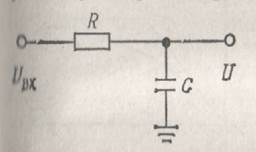
Integrating circuits
Consider the circuit depicted in Fig. 1.18. Voltage on the resistor Ris equal to U in - U,therefore, I = C (dU / dt) = (U in x - U) / R. If the condition U<due to the large value of the product RC , then we obtain C (dU / dt) ~ U in / R or
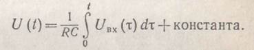 (17)
(17)
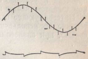
We have found that the circuit integrates the input signal in time! Consider how this circuit provides an approximation of integration in the case of an input signal of rectangular shape: U (t)represents a familiar graph of the exponential dependence that determines the charge of the capacitor (Figure 1.19).
The first segment of the exponential (integral of almost constant value) is a straight line with a constant angle of inclination; as the RC time constant is increased, an ever smaller initial segment of the exponential is used, thereby providing a better approximation of the ideal sawtooth signal.
We note that the condition U< is equivalent to the fact that the current is proportional to the voltage U in.If the current I (t) were the input signal, and not the voltage, then we would get an ideal integrator. The current source can serve as a resistor with a large resistance and with a large drop in voltage on it, and in practice often use an approximation.
In the future, you will learn how to build an integrator without resorting to the condition Uout<. Such an integrator operates over a wide range of frequencies and voltages with a negligibly small error.
Integration circuits are widely used in analog technology. They are used in control systems, feedback circuits, in analog-to-digital conversion and generation of oscillations.
Generators of sawtooth signal
Now you can easily figure out how the sawtooth generator works. This circuit has proved itself well and has found a very wide application: it is used during timing schemes, in sinusoidal and other oscillation generators, in oscilloscope sweeps, in analog-to-digital converters. It is shown in Fig. 1.20.
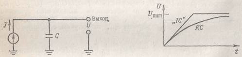
Fig. 1.20. Fig. 1.21.
From the equation for the current flowing through the capacitor, I = C (dU / dt)we obtain U (t) = (I / C) t . The output signal is shown in Fig. 1.21. The linear increase in the signal ceases when the voltage of the current source "runs out," ie, its limiting value is reached. The curve for a simple RC circuit with a resistor connected to a voltage source behaves similarly to the case of reaching the limit of a current source. In Fig. 1.21 this second curve is shown for the case where R is chosen so that the current at zero output voltage is equal to the current source current; while the second curve tends to the same limit as the polygonal line. (In real current sources, the output voltage is limited by the voltage of the power supplies used in them, so this behavior is quite plausible.) In the next chapter on transistors, we will construct simple current source circuits, and in the chapters dealing with operational amplifiers and field effect transistors, their advanced types.
§ 1.6. Inductances and transformers
Inductance
If you understand what a capacitor is, you will understand what inductance is (Figure 1.22).
![]()
Let us compare the inductance and the capacitor with each other; in the inductance, the rate of change of the current depends on the applied voltage, and in the capacitor the rate of change of the voltage depends on the flowing current. The equation of inductance has the following form:
![]() (18)
(18)
where L - inductancein Henry (or mH, μH, etc.). The voltage applied to the inductance causes the current flowing through it, the current changes linearly and the current flows through the capacitor, this will lead to an increase in the voltage across it, with the voltage changing linearly); a voltage of 1V applied to the inductance 1HH leads to an increase in current through the inductance with a speed of 1A in 1s.
Conditionally inductance is represented in the form of several turns of wire - this design has a simple inductance. Other, more sophisticated designs include a core on which the wire is wound. The material for the core is usually iron (plates rolled from iron alloys or manufactured by powder metallurgy methods) or ferrite, which is a brittle non-conductive magnetic material of black color. The core makes it possible to increase the inductance of the coil due to the magnetic properties of the core material. The core can be made in the form of a bar, a torus, or may have some more bizarre shape, for example a "pot" (it is not so easy to describe it in words: imagine a donut baking dish that is split in half).
Inductances find the greatest application in radio frequency circuits, where they are used as radio frequency chokes, and in resonant circuits. A pair of coupled inductances forms such an interesting element as a transformer.
In fact, the inductance is the opposite of the capacitor.
Capacitor - an electronic component intended for the accumulation of electric charge. The ability of a capacitor to accumulate an electric charge depends on its main characteristic - capacity. Capacitor capacitance (C) is defined as the ratio of the amount of electric charge (Q) to voltage (U).
The capacitance of the capacitor is measured in farads (F) - units, named after the British scientist physicist Michael Faraday. Capacity in one farad (1F) is equal to the amount of charge in one pendant (1C), which creates a voltage on the capacitor in one volt (1V). Recall that one pendant (1C) is equal to the value of the charge that has passed through the conductor in just a second (1sec) at current strength in one amp (1A).
However, the pendant is a very large amount of charge relative to how much the capacitors can store. For this reason, microfarads (μF or uF), nanofarads (nF) and picofarads (pF) are usually used to measure capacitance.
- 1μF = 0.000001 = 10 -6 F
- 1nF = 0.000000001 = 10 -9 F
- 1pF = 0.000000000001 = 10 -12 F
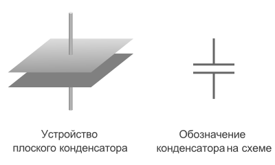
Flat capacitor
There are many types of capacitors of various shapes and internal devices. Consider the simplest and most fundamental - a flat capacitor. A flat capacitor consists of two parallel conductor plates (plates) electrically insulated from each other by air, or a special dielectric material (for example, paper, glass or mica).
Capacitor charge. Current
In its intended use, the capacitor resembles a battery, but still it is very different in principle, maximum capacity, and charge / discharge rate.
Let us consider the operation principle of a flat capacitor. If a power supply is connected to it, negatively charged particles in the form of electrons will begin to collect on one plate of the conductor, on the other - positively charged particles in the form of ions. Since there is an insulator between the plates, the charged particles can not "jump" to the opposite side of the condenser. However, electrons move from the power source to the capacitor plate. Therefore, there is an electric current in the circuit.
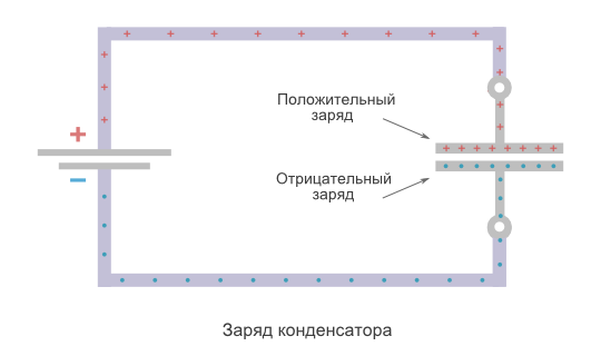
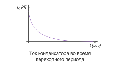
At the very beginning of the inclusion of the capacitor in the circuit, there is more free space on its plates. Consequently, the initial current at this moment meets the least resistance and is the maximum. As the capacitor is filled with charged particles, the current gradually decreases until the free space on the plates is finished and the current does not stop at all.
The time between the states of the "empty" capacitor with the maximum current value, and the "full" capacitor with the minimum current value (ie its absence) is called transition period of the capacitor charge.
Capacitor charge. Voltage
At the very beginning of the transition period of charging, the voltage between the capacitor plates is zero. As soon as charged particles begin to appear on the plates, a voltage arises between the opposite charges. The reason for this is the dielectric between the plates, which "hinders" the charges with opposite sign to the opposite side of the capacitor.
At the initial stage of charging, the voltage rises rapidly, because a large current very quickly increases the number of charged particles on the plates. The more the capacitor is charged, the less current, and then the voltage increases more slowly. At the end of the transition period, the voltage across the capacitor will completely stop increasing, and will equal the voltage at the power source.
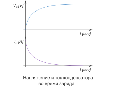
As can be seen on the graph, the capacitor current directly depends on the voltage change.
The formula for finding the capacitor current during the transition period:
- C - Capacitance capacitance
- ΔVc / Δt - Change in voltage across the capacitor over a period of time
Discharge of the capacitor
After the capacitor is charged, turn off the power source and connect the load R. Since the capacitor is already charged, it has turned into a power source. The load R formed the passage between the plates. The negatively charged electrons accumulated on one plate, according to the attractive force between unlike charges, will move toward positively charged ions on the other plate.
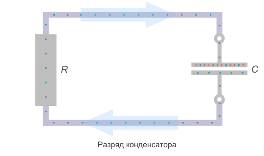
At the moment of connection R, the voltage on the capacitor is the same as after the end of the transition period of charging. The starting current according to Ohm's law will be equal to the voltage on the plates divided by the load resistance.
As soon as there is a current in the circuit, the capacitor will start discharging. As the charge is lost, the voltage will begin to fall. Consequently, the current will also drop. As the voltage and current values decrease, their fall speed will decrease.
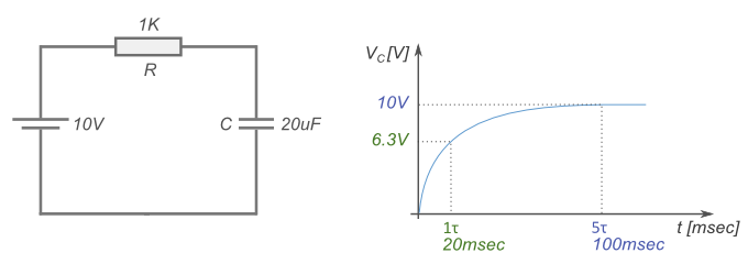
The charging and discharging time of the capacitor depends on two parameters - the capacitance of capacitor C and the total resistance in circuit R. The larger the capacity of the capacitor, the more charge must pass through the circuit, and the longer the charging / discharging process will require (current is defined as the charge amount, passed on the conductor per unit of time). The greater the resistance R, the smaller the current. Accordingly, more time will be required for charging.
The RC product (resistance multiplied by capacity) forms a time constant τ (tau). For one τ, the capacitor is charged or discharged by 63%. For five τ, the capacitor is charged or discharged completely.
For clarity, substitute the values: a capacitor with a capacity of 20 microfarads, a resistance of 1 kilo and a power supply of 10V. The charging process will look like this:
The device of the condenser. What determines the capacity?
The capacitance of a flat capacitor depends on three main factors:
- Plate area - A
- The distance between the plates is d
- Relative permittivity of the substance between the plates - ɛ
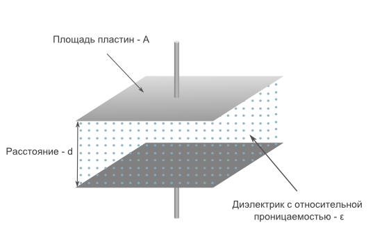
Plate area
The larger the area of the plates of the capacitor, the more charged particles can be placed on them, and the greater the capacitance.
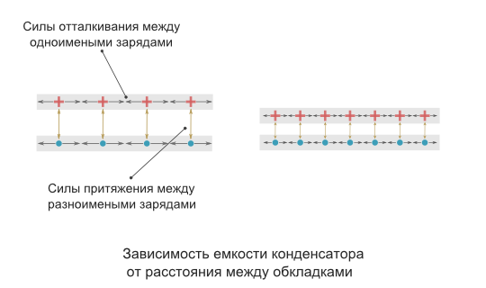
Distance between plates
The capacitance of the capacitor is inversely proportional to the distance between the plates. In order to explain the nature of the influence of this factor, it is necessary to recall the mechanics of the interaction of charges in space (electrostatics).
If the capacitor is not in the electrical circuit, then the charged particles located on its plates are affected by two forces. The first is the repulsive force between the same charges of neighboring particles on one plate. The second is the force of attraction of unlike charges between particles located on opposite plates. It turns out that the closer plates are to each other, the greater the total force of attraction of charges with the opposite sign, and the more the charge can be placed on one plate.
Relative permittivity
No less significant factor affecting the capacity of the capacitor is the property of the material between the plates as relative permittivity ɛ. It is a dimensionless physical quantity that shows how many times the force of interaction of two free charges in a dielectric is less than in a vacuum.
Materials with higher dielectric permittivity make it possible to provide greater capacity. This is explained by the effect polarization - displacement of electrons of dielectric atoms in the direction of a positively charged capacitor plate.
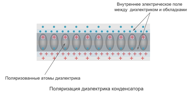
Polarization creates an internal electric field of the dielectric, which weakens the overall difference in the potential (voltage) of the capacitor. The voltage U prevents the flow of Q to the capacitor. Consequently, lowering the voltage facilitates placing a larger amount of electric charge on the capacitor.
Below are examples of dielectric permittivity values for some insulating materials used in capacitors.
- Air - 1.0005
- Paper - from 2.5 to 3.5
- Glass - from 3 to 10
- Mica - from 5 to 7
- Powders of metal oxides - from 6 to 20
Rated voltage
The second most important characteristic after capacity is maximum rated voltage of the capacitor. This parameter indicates the maximum voltage that the capacitor can withstand. Exceeding this value leads to "punching" of the insulator between the plates and a short circuit. The nominal voltage depends on the material of the insulator and its thickness (the distance between the plates).
It should be noted that when working with an alternating voltage, it is necessary to take into account the peak value (the greatest instantaneous voltage value for the period). For example, if the effective voltage of the power supply is 50V, then its peak value will be over 70V. Accordingly, it is necessary to use a capacitor with a rated voltage of more than 70V. However, in practice, it is recommended to use a capacitor with a nominal voltage that is at least twice as high as the maximum possible voltage that will be applied to it.
Leakage current
Also, when the condenser is operating, a parameter such as leakage current is taken into account. Since in real life a dielectric between the plates still passes a small current, this leads to a loss with time of the initial charge of the capacitor.
Length and distance Weight Measures volume of bulk products and food products Area Volume and units in cooking recipes Temperature Pressure, mechanical stress, Young's modulus Energy and work Power Strength Time Linear velocity Flat angle Thermal efficiency and fuel economy Numbers Information amount units Exchange rates Dimensions women's clothing and shoes Sizes of men's clothing and footwear Angular velocity and speed of acceleration Acceleration Angular acceleration Density Specific volume Moment of inertia Momen (by mass) Energy density and specific heat of combustion of fuel (by volume) Temperature difference Thermal expansion coefficient Thermal resistance Specific thermal conductivity Specific heat capacity Energy exposure, thermal radiation power Heat flux density Heat transfer coefficient Volumetric flow Mass flow Molar consumption Density of mass flow Molar concentration Mass concentration in solution Dynamic (absolute) viscosity Kinematics (SPL) Brightness Light intensity Illumination Resolution in computer graphics Frequency and wavelength Optical force in diopters and focal length Optical force in diopters and lens magnification (×) Electric charge Linear density of charge Surface charge density Bulk density of charge Electric current Linear current density Surface current density Electrical field strength Electrostatic potential and voltage Electrical resistance Specific electrical resistance Electrical conductivity Specific electrical conductivity Electrical capacitance Inductance American wire gauge Levels in dBm (dBm or dBm), dBV (dBV), watts and other units Magnetomotive force Magnetic field strength Magnetic flux Magnetic Induction The power of the absorbed dose of ionizing radiation. Radioactivity. Radioactive decay Radiation. Exposure dose Radiation. Absorbed dose Decimal consoles Data transmission Typography and image processing Units of timber volume measurement Calculation of molar mass Periodic system of chemical elements DI Mendeleeva
1 farad [Ph] = 1,000,000 microfarads [μF]
Initial value
The converted value
farad exafarad petafarad terafarad gigafarad megafarad kilofarad hectofarad decafarad decafarad centifarad millifarad microfarad nanofarad picofarad femtofarad attofarad pendant per volt abfarad unit of capacitance SGM staffadad capacitance unit SGSE
Metric system and SI
Read more about capacitance
General information
An electrical capacitance is a quantity that characterizes the ability of a conductor to accumulate a charge equal to the ratio of the electric charge to the potential difference between conductors:
C = Q / Δφ
Here Q - electric charge, measured in coulombs (Cl), - potential difference, measured in volts (V).
In the SI system, the electrical capacity is measured in Farad (F). This unit is named after the English physicist Michael Faraday.
Farad is a very large capacity for an insulated conductor. Thus, a metal solitary ball with a radius of 13 solar radii would have a capacitance equal to 1 farad. And the capacity of a metal ball the size of the Earth would be about 710 microfarads (μF).
Since 1 farad is a very large capacitance, therefore, smaller values are used, such as: microfarad (μF) equal to one millionth Farad; nanofarad (nF), equal to one billionth; picofarad (pF), equal to one trillionth Farad.
In the CGSE system, the basic unit of capacity is a centimeter (cm). 1 centimeter of capacity is the electric capacity of a ball with a radius of 1 centimeter, placed in a vacuum. The CGE is an extended system of GHS for electrodynamics, that is, a system of units in which centimeter, gram, and second are taken as base units for calculating length, mass and time, respectively. In extended GHS, including CGEE, some physical constants are taken as a unit to simplify formulas and facilitate calculations.
Using a container
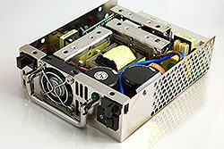
Capacitors - devices for accumulating charge in electronic equipment
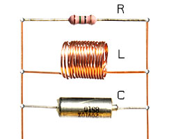
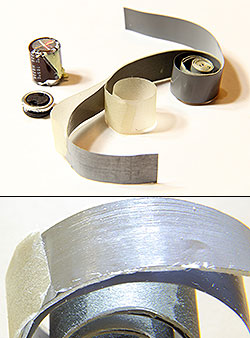
The concept of capacitance refers not only to the conductor, but also to the capacitor. A capacitor is a system of two conductors separated by a dielectric or a vacuum. In the simplest form, the capacitor design consists of two electrodes in the form of plates (plates). The capacitor (from Latin condensare) is a two-electrode device for accumulating the charge and energy of the electromagnetic field, in the simplest case, two conductors separated by some kind of insulator. For example, sometimes radio amateurs, in the absence of ready-made parts, fabricate trimmer capacitors for their circuits from wire lengths of different diameters, insulated with a varnish coating, while a thinner wire is wound onto a thicker one. By regulating the number of turns, radio amateurs accurately adjust the circuit of the equipment to the desired frequency. Examples of the image of capacitors in electrical circuits are shown in the figure.
Historical reference
Another 275 years ago, the principles of creating capacitors were known. So, in 1745 in Leiden, the German physicist Ewald Jürgen von Kleist and the Dutch physicist Peter van Mushenbrook created the first condenser - the "Leiden jar" - in it the walls of a glass jar were the dielectric, and the plates were water in a vessel and the palm of the experimenter holding the vessel. Such a "bank" made it possible to accumulate a charge of the order of a microculture (μC). After it was invented, experiments and public performances were often performed with it. To do this, the bank was first charged with static electricity, rubbing it. After that, one of the participants touched the bank with his hand, and received a slight electric shock. It is known that 700 Parisian monks, holding hands, conducted a Leiden experiment. At the moment when the first monk touched the head of the can, all 700 monks, reduced by one convulsion, screamed in horror.
In Russia, the "Leiden Bank" came thanks to the Russian Tsar Peter I, who met Mushenbruk during his travels around Europe, and learned more about the experiments with the "Leiden Bank." Peter I established the Academy of Sciences in Russia, and ordered Musenbrook various instruments for the Academy of Sciences.
In the future, the capacitors improved and became smaller, and their capacity - more. Condensers are widely used in electronics. For example, a capacitor and an inductor form an oscillatory circuit that can be used to tune the receiver to the desired frequency.
There are several types of capacitors characterized by a constant or variable capacitance and dielectric material.
Examples of capacitors
The industry produces a large number of types of capacitors for various purposes, but their main characteristics are capacitance and operating voltage.
Typical value capacities capacitors vary from picofarad units to hundreds of microfarads, except ionistors, which have a somewhat different character of reservoir formation - due to the double layer at the electrodes - in this they are similar to electrochemical accumulators. Supercapacitors based on nanotubes have an extremely developed surface of electrodes. For these types of capacitors, typical capacitance values are dozens of farads, and in some cases they are able to replace traditional electrochemical batteries as current sources.
The second most important parameter of capacitors is its operating voltage. Exceeding this parameter can lead to the failure of the capacitor, so when constructing real circuits, it is customary to use capacitors with twice the value of the operating voltage.
To increase the capacitance or operating voltage, use the combination of capacitors in the batteries. When the two same-type capacitors are connected in series, the operating voltage is doubled, and the total capacity is reduced by half. With parallel connection of two identical capacitors, the operating voltage remains the same, and the total capacity is doubled.
The third most important parameter of capacitors is temperature coefficient of capacity change (TKE). He gives an idea of the change in capacity in conditions of temperature changes.
Depending on the purpose of use, the capacitors are divided into general-purpose capacitors, the requirements for the parameters of which are not critical, and for special-purpose capacitors (high-voltage, precision and with different TKE).
Marking of capacitors
Like resistors, depending on the size of the product, full marking can be used, indicating the nominal capacity, the class of deviation from the nominal and the operating voltage. For small-sized capacitor designs, code marks of three or four digits, mixed alphanumeric marking and color marking are used.
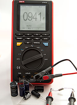
Corresponding tables for the recalculation of markings at nominal, working voltage and TKE can be found on the Internet, but the most effective and practical method of checking the nominal value and serviceability of the real circuit element is to directly measure the parameters of the evaporated capacitor using a multimeter.
A warning: since capacitors can accumulate a large charge at a very high voltage, in order to avoid electric shock it is necessary to discharge it before measuring the capacitor parameters, shorting its terminals with a wire with a high resistance of external insulation. The nominal wires of the measuring device are best for this purpose.
Oxide capacitors: This type of capacitor has a large specific capacitance, i.e., capacitance per unit of weight of the capacitor. One lining of such capacitors is usually an aluminum tape covered with a layer of aluminum oxide. The second plate is an electrolyte. Since the oxide capacitors have a polarity, it is of fundamental importance to include such a capacitor in the circuit strictly in accordance with the voltage polarity.
Solid-state capacitors: in them instead of the traditional electrolyte, an organic polymer, conductive current, or semiconductor is used as an electrode.
Variable capacitors: The capacity can be changed mechanically, by electric voltage or by means of temperature.
Film Capacitors: The capacitance range of this type of capacitor is approximately 5 pF to 100 mF.
There are other types of capacitors.
Ionistory
Nowadays, ionists are gaining popularity. Ionistor (supercapacitor) is a hybrid of a capacitor and a chemical current source, the charge of which accumulates at the interface between two media, the electrode and the electrolyte. The creation of ionistors was begun in 1957, when a capacitor with a double electric layer on porous carbon electrodes was patented. The double layer, as well as the porous material, helped to increase the capacitance of such a capacitor by increasing the surface area. In the future this technology was supplemented and improved. On the market ionists came out in the early eighties of the last century.
With the advent of ionistors, it became possible to use them in electrical circuits as sources of voltage. Such supercapacitors have a long service life, low weight, high charge-discharge rates. In the future, this type of capacitor can replace conventional batteries. The main disadvantages of ionistors are the specific energy (energy per unit of weight), the low operating voltage and the significant self-discharge that is smaller than for electrochemical batteries.
Ionistors are used in Formula 1 cars. In energy recovery systems, braking produces electricity, which accumulates in the flywheel, batteries or ionistors for further use.
In consumer electronics, ionistors are used to stabilize main power and as a backup power source for devices such as players, flashlights, in automatic utility meters and other devices with battery power and varying load, providing power at increased load.
In public transport, the use of ionistors is particularly promising for trolleybuses, as it becomes possible to implement an autonomous course and increase maneuverability; Also ionists are used in some buses and electric vehicles.
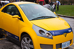
Electric cars in the present time are produced by many companies, for example: General Motors, Nissan, Tesla Motors, Toronto Electric. University of Toronto together with Toronto Electric developed a fully Canadian electric car A2B. It uses ionists together with chemical power sources, the so-called hybrid electrical energy storage. The engines of this car are powered by batteries weighing 380 kilograms. Also used for recharging are solar panels mounted on the roof of an electric vehicle.
Capacitive touch screens
In modern devices, touch screens are increasingly being used, which allow controlling devices by touching panels with indicators or screens. Touch screens are of different types: resistive, capacitive and others. They can react to one or more simultaneous touches. The principle of operation of capacitive screens is based on the fact that an object of high capacitance conducts alternating current. In this case, this object is the human body.
Surface-capacitive screens

Thus, the surface-capacitive touch screen is a glass panel covered with a transparent resistive material. As a resistive material, an alloy of indium oxide and tin oxide having a high transparency and low surface resistance is usually applied. The electrodes, which supply a small alternating voltage to the conducting layer, are located at the corners of the screen. When you touch this screen with your finger, a leakage occurs, which is recorded in four corners by sensors and transmitted to the controller, which determines the coordinates of the touch point.
The advantage of such screens is durability (about 6.5 years of pressing with an interval of one second or about 200 million presses). They have high transparency (about 90%). Thanks to these advantages, capacitive screens have already actively started to replace resistive screens since 2009.
The disadvantage of capacitive screens is that they do not work well at negative temperatures, there are difficulties with using such glove screens. If the conductive coating is located on the outer surface, the screen is sufficiently vulnerable, so capacitive screens are only used in those devices that are weatherproof.
Projection-capacitive screens
In addition to surface-capacitive screens, there are projection-capacitive screens. Their difference lies in the fact that on the inside of the screen there is a grid of electrodes. The electrode to be touched, together with the human body, forms a condenser. Thanks to the grid, you can get the exact coordinates of the touch. The projection-capacitive screen reacts to the touch in thin gloves.
Projection-capacitive screens also have high transparency (about 90%). They are durable and strong enough, so they are widely used not only in personal electronics, but also in vending machines, including those installed on the street.
Do you find it difficult to translate a unit of measurement from one language to another? Colleagues are ready to help you. Post a question to TCTerms and within a few minutes you will receive an answer.