The alternative alternator is designed to convert mechanical energy into electrical energy. Its rotor rotates from the primary engine, which can serve as a turbine, internal combustion engine, electric motor.
What does a synchronous generator look like?
Synchronous machines include those in which the rotor has the same frequency of rotation with a magnetic field:
n = 60 ∙f/ p, where
f - frequency of the network;
p - number of pairs of poles of the stator.
Principle of operation
The stator and the rotor are the main components of the synchronous generator (SG).
Principle of operation of a synchronous generator
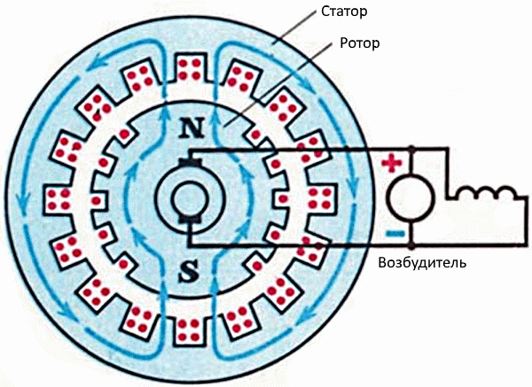
As shown in the figure, a synchronous generator generates energy most often when the rotor rotates together with a magnetic field whose lines intersect the stator winding located motionless. The field is created from an additional pathogen (an additional generator, battery, and other sources).
The process can occur on the contrary - the rotating conductor is in a stationary magnetic field. Here there is a problem of current collection through the collector unit. For AC generators of low power this circuit is quite suitable. Usually it is used in mobile installations.
In the SG produced EMF:
e = 2πBlwDn, where
B is the magnetic induction;
l - length of the stator groove;
w is the number of turns in the stator winding;
D is the inner diameter of the stator.
The basic electric power industry is built at a voltage of 15-40 kV. Transmission of energy through the collector SG is difficult. In addition, the movable winding is subject to impact loads and rotation with variable speed, which creates problems with insulation. Because of this, the armature windings are made stationary, since the main energy passes through them. The exciter power does not exceed 5% of the total SG power. This allows the current to be drawn through the movable assembly.
In AC machines of low power (several kilowatts), the rotor is manufactured with permanent magnets (neodymium, etc.). It does not require the installation of movable contacts, but then there are difficulties with the regulation of the output voltage.
Generator device
The stator has a general principle of operation with an asynchronous and differs little from it. Its iron is collected from electrical steel plates, separated by insulating layers. The AC winding is located in the slots. The most common is a three-phase synchronous generator. The wires of the windings are securely fixed and insulated, because the load is connected through them.
The rotor is executed with clearly defined poles or without protruding poles.
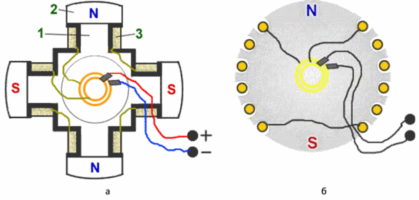
Types of poles of a synchronous generator: a) - speakers; b - implicit
The first are made for slow-moving machines, for example, with hydraulic turbines. For rotating alternators with high speed, the principle of action is to apply stronger implicitly expressed poles.
The SG can operate in the engine or alternator modes. It is important what kind of cooling method is used here. Usually, impellers are installed on the shaft, cooling the rotor on both sides. Air before ventilation passes through the filter. In the closed system, the same air circulates through the heat exchangers.
The most effective cooling agent is hydrogen, 14.5 times lighter than air. The principle of cooling is similar.
The windings of the alternator are output by the ends to its junction box. For three-phase - connection is made in a star or in a triangle.
The synchronous generator preferably provides support for the sinusoidal alternating voltage. This is achieved by changing the shape of the pole pieces, and the non-pole pole rotor has a specific arrangement of turns in its slots.
Anchoring reaction
When the output is connected to an external load, an electric current flows in the stator windings. The resulting magnetic field is superimposed on the field that creates the rotor.
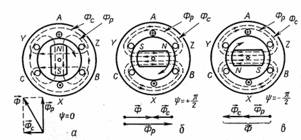
Anchor response for different types of load
With the active load, the current and EMF coincide in phases (shown in the figure above - a). It becomes maximum if the poles of the rotor are located opposite the anchor windings. The main magnetic flux and the armature formed from the reaction are perpendicular and, when applied, form a somewhat larger resulting flux, increasing the EMF.
The inductive load leads to a decrease in EMF, since the flows are directed counter-way (shown in the figure above - b).
The capacitive load causes coincidence of flow directions, as a result of which the EMF increases.
Increasing the load results in a larger anchor response, leading to a change in the output voltage, which is undesirable. In practice, this process is controlled by a change in excitation, which reduces the degree of influence of the anchor reaction on the ground field.
Working modes of the SG
Normal modes of operation are characterized by arbitrarily long periods of time. These include deviations in power factors, output voltage up to 5% and frequency up to 2.5% of the nominal values, etc. Tolerances for deviations are determined by heating the aggregates and are specified by standards or are guaranteed by manufacturers.
And normal modes of operation are unacceptable for continuous operation and are associated with the appearance of overloads, with underexcitation, transitions to asynchronous modes. This mode of operation is associated with deviations in the network: short circuits, loads of variable action, uneven phase loading.
The normally functioning device is influenced by the connected network, where disruptions in the functioning of individual consumers cause asymmetry and distortion of the waveform. Because of this, the windings or the generator can overheat.
Continuous operation of the generator is possible if the phase currents in the turbogenerators differ by up to 10% and up to 20% in synchronous compensators and hydrogenerators.
The distortion of the sinusoid on the SG is due to the powerful rectifiers, converters, electric transport, etc.
It is important for synchronous machines that the cooling system function properly. If the cooling water costs reach 70% of the nominal value, a warning alarm is triggered. If the cooler flow is reduced by half, the device must be unloaded in 2 minutes, and then shut off in no more than 4 minutes.
Generator characteristics:
- at idling, when the armature winding is not closed, the dependence of the EMF on the excitation currents is established, and the magnetization index of the cores of the machine is determined;
- external characteristic - the dependence of the output voltage on the load currents;
- adjusting characteristics, manifested in the dependence of the excitation currents on the load while automatically maintaining the specified output parameters.
Types of generators
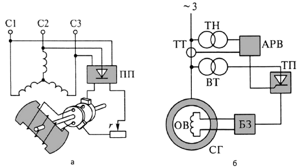
Generators are distinguished by excitation methods. In autonomous installations in transport, in aviation, on ships self-excitation is used due to residual magnetization. The method is distinguished by its reliability and ease of use. A common option here is the selection of energy from the stator winding that passes through the step-down transformer and the semiconductor converter PP, as a result of which a constant current flows through the collector to the excitation winding (shown in the figure below -a).
The principle of self-excitation of a synchronous generator
Another scheme realizes self-excitation also by feeding an alternating current from the stator winding through the rectifier transformer BT and the thyristor of the transformer to the excitation winding OB (shown in the figure above-b). The thyristor is automatically controlled by the ARV excitation controller by signals from the input of the generator SG through voltage transformers TH and CT current. The protection unit of the short-circuit protection does not permit the formation of an overvoltage and overcurrent in the excitation winding.
Another design contains an additional synchronous or asynchronous machine with excitation from stator windings. The figure below shows such an SG system with an excitation winding OB and a three-phase stator winding. In this case, the rotor of the main generator has a common shaft with anchor windings of excitation OB 1 and OB 2 of an additional exciter PV. The excitation current is regulated by rheostats r 1 and r 2 . The device is not inferior in terms of speed to installations with self-excitation, but the design is more complex, and the dimensions are larger.
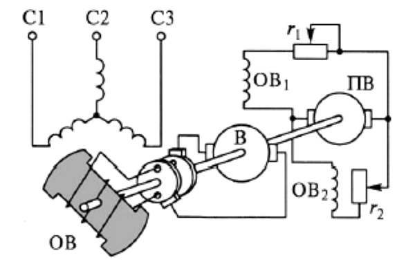
Excitation system with additional generator
A non-contact excitation system is also used, where the SG has no movable contacts for energy transfer. Brushes with a collector are only podvozbuditel PV, which feeds the post
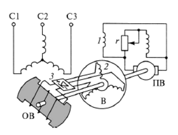
Non-contact excitation system of a synchronous generator
the current of the exciter I
Video. Synchronous machines
It is possible to note the following modern trends in the development of the technology for the production of synchronous machines:
- improvement of structures;
- use of new materials to reduce the thickness of insulation and increase power to 10%;
- application of microprocessors for monitoring the condition of machines;
- perfection of modes of air cooling.
 The primary motors of synchronous generators with pronounced poles are usually hydraulic turbines, which are slow-moving machines. At a high rotational speed, such a rotor device can not provide the necessary mechanical strength, and therefore the high-speed machines have rotors with implicitly expressed poles (iso, 6). The cores of rotors with implicitly expressed poles are usually made of solid forgings, on the surface of which the grooves are milled. After the winding of the excitation windings on the rotor of the groove, it is clogged with wedges, and the frontal connections of the excitation winding are strengthened by steel bandages placed on the end parts of the rotor. With this design of the rotor, higher speeds are allowed. For generators with implicitly expressed poles, the primary engines are usually steam turbines that belong to the number of high-speed machines.
 Synchronous motors. Construction, principle of operation
Unlike an asynchronous motor, the synchronous motor speed is constant at different loads. Synchronous motors are used for driving constant speed machines (pumps, compressors, fans).
In the stator of the synchronous motor, a winding is placed, connected to the three-phase current network and forming a rotating magnetic field. The rotor of the engine consists of a core with an excitation winding. The excitation winding through the contact rings is connected to a direct current source. The current of the excitation winding creates a magnetic field, a magnetizing rotor.
Rotors of synchronous machines can be explicitly polar (with explicitly expressed poles) and non-polar (with implicitly expressed poles). In Fig. 1a shows the core 1 of the pole-pole rotor with protruding poles. At the poles there are coils of excitation 2. Figure 1b shows an implicit-pole rotor, which is a ferromagnetic cylinder 1. On the rotor surface, grooves are milled in the axial direction into which the excitation winding 2 is laid.
Consider the principle of the synchronous motor on the model (Figure 11).
A synchronous jet engine is a synchronous motor, on the rotor of which there is no excitation winding.
The rotor of a synchronous jet engine is made of ferromagnetic material and must have clearly expressed poles. Rotating magnetic field of the stator magnetizes the rotor. The polar pole rotor has unequal magnetic resistance along the longitudinal and transverse axes of the pole. The lines of force of the stator magnetic field bend, trying to pass along the path with a lower magnetic resistance. Deformation of the magnetic field will cause, due to the elastic properties of the lines of force, the reactive torque that rotates the rotor in synchronism with the stator field.
If a braking torque is applied to the rotor, the axis of the rotor's magnetic field will rotate by an angle θ with respect to the axis of the stator magnetic field.
With increasing load this angle increases. If the load exceeds a certain allowable value, the motor will stop, will fall out of sync.
Synchronous motors do not have a starting torque. This is because the electromagnetic torque acting on the fixed rotor changes its direction twice during the period T of the alternating current. Due to its inertia, the rotor does not have time to move from the place and develop the required number of revolutions.
Currently, the synchronous motor is started asynchronously. In the grooves of the poles of the rotor an additional short-circuited winding is laid.
Rotating magnetic field of the stator induces eddy currents in the short-circuited starting winding. When these currents interact with the stator magnetic field, an asynchronous electromagnetic moment is produced, leading the rotor into rotation. When the rotor speed approaches the rotational speed of the stator field, the motor retracts into synchronism and rotates at a synchronous speed. The short-circuited winding does not move relative to the field, the eddy currents in it are not induced, the asynchronous starting torque becomes zero.
It was shown that electric machines are reversible, i.e. can operate both a generator and an engine. However, synchronous machines are often used as generators, and asynchronous machines are used as engines. It was also shown that the stator arrangement of synchronous and asynchronous machines is the same, and the rotors are arranged in different ways.
The stator is a hollow bonded cylinder with longitudinal grooves on its inner surface. In the grooves the stator winding is laid, most often three-phase.
The rotor of a synchronous generator is essentially an electromagnet mounted on the shaft of the machine, which under the action of the primary motor rotates inside the stator boring. The principle of operation of the synchronous generator can be explained with the help of Fig. 3, which shows a cross-section of a single-phase two-pole synchronous generator, in which the rotor winding is represented by a bipolar electromagnet coil, and the stator winding - by one turn. The rotor is driven by a primary engine - diesel engine, turbine, wind turbine, etc.
If the winding of the rotor is connected to the rotor winding by means of rings mounted on the generator shaft and fixed carbon brushes touching the rings, the rotor winding will create an electromagnetic field that closes both along the rotor and the stator core, passing twice through the air gap between the rotor and the stator.
When the rotor rotates, the magnetic flux Φ created by it crosses the conductors of the stator winding and induces in them an EMF, the instantaneous value of which
equally e = B. L. V
and the direction is determined by the rule of the right hand.
In this formula:
AT - magnetic induction of the flow Φ at the location of the conductor [T].
L- the active length of the two conductors of the turn - under both poles of the electromagnet [m].
V- circumferential velocity of the poles relative to the conductors [m / s].
The EMF of the stator winding can be represented in vector form, or in the form of a sinusoidal function, as shown in the figure
The distribution of the magnetic induction of an electromagnet on which the shape of the curve depends e = f (t), is determined by the profile of the pole pieces. It is chosen so that when the EMF electromagnet is turned uniformly, the winding of the stator winding is sinusoidal. If any resistance Z is connected to the terminals A - X of the stator winding, then an alternating current will flow along the closed electric circuit, the frequency of which depends on the rotor speed n [rpm] and the number of pole pairs p of the electromagnet of the rotor.
In the case where the conductors of the turn are crossed by the north and south S poles of the field once, the current in the stator winding circuit will make one cycle of change. In a bipolar machine p = 1. If one rotation of the rotor occurs in 1 second, the current frequency in the stator winding circuit is 1 Hz.
With the number of pairs of poles equal to p, the frequency of the current will be p Hz. If the rotor speed is n rpm. or n / 60 rpm, then the frequency of the current will be f = p.n / 60 (Hz)
To create a standard frequency f = 50 Hz, the rotor speed must be strictly defined. From the formula f = p. n / 60 (Hz) we have n =50 . 60 / p = 3000 / p
This allows you to create a table:
|
n rpm. |
When p = 1, 2, 3, 4, the cars are considered to be high-speed. This is usually turbo and diesel generators in power plants and in industry. When p = 12 ...24 machines are slow-moving. Usually these are hydro generators in hydroelectric power plants.
To create a three-phase current system on the stator, it is necessary to place not one but three turns shifted along the circumference of the stator 1/3 double pole pitch, as shown in the figure. For bipolar machines this shift is 1/3 of the stator circumference.
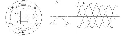
This spatial displacement of the windings of the stator winding causes a time shift of their EMF and currents, i.e. phase shift to 1/3 period.
If the circuits of the windings of the stator winding are shorted to load resistances, then currents will flow along them, also shifted by 1/3 of the period. A three-phase system of currents is formed, which creates its magnetic field rotating along the magnetic circuit in the same direction and with the same rotation frequency as the rotor of the machine, i.e. synchronously with the rotor. In this case, the magnetic field of the stator interacts with the magnetic field of the rotor. Since the core of the stator with the winding is called the armature of the machine, this interaction is called the armature response.
For the reason that the rotational speed of the stator field and the rotor speed are the same, machines of this type are called synchronous.
So, to increase the load of the synchronous generator, it is necessary to increase the current in the stator winding, and for this it is necessary to reduce the resistance value in the winding circuit.
It should be noted that the currents in the stator winding, interacting with the magnetic flux of the rotor, create electromagnetic forces and a moment directed towards the moment of the primary motor. In other words, when loaded, a synchronous generator generates a braking torque, which must be prepared by the primary engine. Consequently, with increasing the load of the synchronous generator, it is necessary to increase the power and torque of the primary motor.
Synchronous machines are divided according to the type of the rotor device into apparent and non-pole poles. Have explicitlygenerators, the rotor is a cross on which the pole cores are fastened with coils of an electromagnet or as they are called coils of the excitation winding. Usually they are slow-moving cars with a large number of poles. Accordingly, the crosspiece of the rotor has a large number of faces. The pole pieces are fixed to the crosspiece by means of special shanks and wedges which, when the rotor rotates, increase the pole pieces in their places.
Non-pole-pole generatorsAre high-speed machines with speeds of 3000 or 1500 rpm. The rotor is made in the form of a cylindrical forging made of high-quality electrical steel, on the surface of which longitudinal grooves are milled. In them, the DC excitation winding is laid, which consists of separate coils (turns) of different widths.
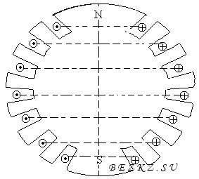
Each coil is placed in two grooves, which are located symmetrically with respect to the longitudinal axis of the section of the rotor. The grooves occupy approximately 2/3 of the circumference of the rotor. All the coils are connected in series, forming a distributed excitation winding of the synchronous generator. To protect the excitation winding by centrifugal forces, the conductors in the slots are secured with wedges of non-magnetic metals, as shown in the figure.
The frontal parts of the windings of the excitation winding, located outside the rotor, are fixed in their places with special bandages (rings or sleeves made of non-magnetic steel).
The connection scheme of the excitation winding provides for alternating the polarity of the poles of the rotor, and the sine of the stator winding is achieved by distributing the excitation coils in the grooves.
If in the above-mentioned asynchronous machines the rotor had a rotation frequency different from the rotational frequency of the stator magnetic field, then in synchronous these frequencies are equal.
Synchronous machines can work as generators and motors.
Depending on the type of drive synchronous generators also received their names.
Turbogenerator, for example, is a generator driven by a steam turbine, a hydrogenerator rotates a water wheel, and a diesel generator is mechanically connected to an internal combustion engine.
Synchronous motors are widely used to drive powerful compressors, pumps, fans.
Synchronous micromotors are used to drive the tape mechanisms of recording instruments, tape recorders, etc.
6.1. CONSTRUCTION AND PRINCIPLE OF ACTION OF THE SYNCHRONOUS GENERATOR
The stator of a synchronous machine does not differ in design from the stator of an induction motor. The stator slots receive a three-phase, two-phase or single-phase windings.
A noticeable difference is the rotor, which in principle is a permanent magnet or electromagnet.
This imposes special demands on the geometric shape of the rotor. Any magnet has poles, the number of which can be two or more.
In Fig. 6.1.1 shows two designs of generators, with a low-speed and high-speed rotor.
As a rule, turbogenerators are fast. The number of pairs of magnetic poles is unity. For such a generator to generate an electric current of a standard frequency f = 50 Hz, it must be rotated at a frequency
At hydropower plants, rotation of the rotor depends on the movement of the water flow. But even with slow rotation, such a generator must produce an electrical current of standard frequency f = 50 Hz.
Therefore, for each hydroelectric power plant, a generator is constructed, to a certain number of magnetic poles on the rotor.
As an example, we give the parameters of a synchronous generator operating at the Dnieper Hydroelectric Power Station.
The water flow rotates the generator rotor with a frequency of n = 33.3 rpm. Setting the frequency f = 50 Hz, we determine the number of pairs of poles on the rotor:
The principle of the synchronous generator is based on the phenomenon of electromagnetic induction. A rotor with magnetic poles creates a rotating magnetic field, which, crossing the stator winding, induces EMF in it. When connected to a load generator, the generator will be the source of alternating current.
6.2. EMF SYNCHRONOUS GENERATOR
As was shown above, the magnitude of the emf induced in the stator winding is quantitatively related to the number of winding turns and the rate of change of the magnetic flux:
Passing to the actual values, the expression of the EMF can be written in the form:
where n is the rotor speed of the generator,
Ф is the magnetic flux,
c is a constant coefficient.
When the load is connected, the voltage at the generator terminals varies to varying degrees. Thus, an increase in the active load does not have a noticeable effect on the voltage. At the same time, inductive and capacitive loads affect the output voltage of the generator. In the first case, the load growth demagnetizes the generator and reduces the voltage, in the second it bias and increases the voltage. This phenomenon is called anchor reaction.
To ensure the stability of the generator output voltage, it is necessary to regulate the magnetic flux. When it is weakened, the machine needs to magnetize, with increasing - demagnetize. This is done by controlling the current supplied to the excitation winding of the generator rotor.
6.3. SYNCHRONOUS ENGINE
6.3.1. CONSTRUCTION AND PRINCIPLE OF ACTION
The design of the synchronous motor is the same as that of the synchronous generator.
When a current is supplied to the three-phase winding of the stator, a rotating magnetic field appears in it. Its rotation frequency is determined by the formula:
where f is the frequency of the mains current,
p is the number of pole pairs on the stator.
The rotor, which is often an electromagnet, will strictly follow the rotating magnetic field, i.e. its rotational speed is n 2 = n 1.
Let's consider the principle of the synchronous motor on the following conditional model (Figure 6.3.1.). Let the stator magnetic field be simulated by a system of rotating magnetic poles N-S.
The rotor of the engine is also a system of electromagnets S-N, which are "coupled" to the poles on the stator. If there is no load on the motor, the axes of the stator poles will coincide with the axes of the rotor poles (= 0).
If the mechanical load is connected to the rotor, the axes of the poles of the stator and the rotor can diverge at some angle.
However, the "magnetic coupling" of the rotor with the stator will continue, and the rotor speed will be equal to the synchronous stator frequency (n 2 = n 1). At large values, the rotor can exit the "clutch" and the motor will stop.
The main advantage of a synchronous motor in front of an asynchronous motor is the provision of a synchronous rotor speed with considerable load fluctuations.
6.3.2. SYNCHRONOUS ENGINES START-UP SYSTEM
As we have shown above, the synchronous rotation of the rotor is provided by the "magnetic coupling" of the poles of the rotor with the rotating magnetic field of the stator.
At the first moment of starting the engine, the rotating magnetic field of the stator appears almost instantaneously. The rotor, having a considerable inertial mass, can not immediately come into synchronous rotation. It must be "overclocked" to a subsynchronous speed by some additional device.
For a long time, the role of the accelerating engine was played by an ordinary asynchronous motor, mechanically connected with a synchronous motor.
The rotor of the synchronous motor is rotated to a subsynchronous speed. Then the motor itself is retracted into synchronism.
Usually, the power of the starting motor is 5-15% of the power of the synchronous motor. This allows the synchronous motor to run only idle or with a small load on the shaft.
The use of a starting motor with a power sufficient to start a synchronous engine under load makes such an installation cumbersome and expensive.
Recently, the so-called asynchronous start system synchronous motors. To this end, the rods are clogged into pole pieces, resembling the short-circuited winding of an induction motor (Figure 6.3.2.1).
In the initial period of the start-up, the synchronous motor operates as an asynchronous motor, and in the subsequent it works as a synchronous motor. For safety reasons, the excitation winding is short-circuited in the initial start-up period, and at the final one, it is connected to a constant-current source.
6.4. REACTIVE SYNCHRONOUS ENGINE
In laboratory practice, in everyday life and in low-power mechanisms, the so-called reactive synchronous motors.
From conventional classic machines, they differ only in the design of the rotor. The rotor here is not a magnet or an electromagnet, although in shape it resembles a pole system.
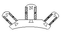
The operating principle of the reactive synchronous motor is different from that considered above. Here, the operation of the motor is based on the free orientation of the rotor in such a way as to provide the magnetic stator flux with better magnetic conductivity (Figure 6.4.1).
Indeed, if at some point in time the maximum magnetic flux is in phase A-X, then the rotor will occupy a position along the flow of FA. After 1/3 of the period, the maximum flux will be in phase B - Y. Then the rotor will unfold along the flow of the PV. After another 1/3 period, the rotor will be oriented along the flow. FS. So the rotor will rotate continuously and synchronously with the rotating magnetic field of the stator.
In school practice, sometimes, in the absence of special synchronous motors, there is a need for synchronous transmission.
This problem can be solved with a conventional asynchronous motor if the rotor is given the following geometric shape (Figure 6.4.2).
6.5. STEP MOTOR
This type of engine is a DC machine, although its operation principle resembles a synchronous jet engine.
As can be seen from Fig. 6.5.1, the stator of the engine has six pairs of protruding poles.
Each two coils located at opposite poles of the stator form a control winding included in the DC network. The rotor is a bipolar one.
If you connect the coils of poles 1 - 1 "to the DC source, the rotor will be located along these poles.If you use the coils of the poles 2 - 2" and the coils of the poles 1 - 1 "to de-energize, the rotor will turn and take a position along the field 2 - 2 ". The same rotation of the rotor will occur if you include 3 - 3 poles in the coil network. "So, in steps, the rotor will" follow "its control winding.
The advantage of stepper motors is that they completely lack "self-propelled". They are rotated and fixed with a pitch proportional to the number of poles on the stator. This quality makes it indispensable in particularly precise mechanisms (for clock drive, nuclear fuel feeding mechanisms in reactors, in CNC machines, etc.).
The control of stepper motors is carried out using various electronic devices (Schmidt triggers, etc.).
6.6. COLLECTOR VEHICLE ENGINE
Brushless asynchronous and synchronous motors with many positive qualities have significant drawbacks. They do not allow a sufficiently smooth and economical rotation control.
This gap is partially replenished by the collector motors of alternating current.
Collector motors are single-phase and three-phase.
The rotor of a single-phase collector motor is made in the form of a cylinder with phase windings, the stator is obviously pole.
Since the winding of the poles of the stator, connected to the alternating current network, creates a pulsating magnetic field, all elements of the machine's magnetic circuit are recruited from separate electrical steel sheets.
The torque in a single-phase collector motor is created by the interaction of the currents in the rotor winding with the magnetic flux of the poles. In Fig. 6.6.1. The scheme of connection to the collector motor network is shown.
The collector motors can operate both from the AC mains and from the DC network. This circumstance served to assign to them the name of universal collector motors. Collector motors are widely used to drive sewing machines, vacuum cleaners, etc.
Any synchronous machine consists of two main parts: stationary stator and rotating rotor (Figure 4.1). The stator and the rotor are separated by an air gap, which in large synchronous machines is usually much larger than for asynchronous machines of equal capacity.
Fig. 4.1. Apparatus of a pole-pole synchronous machine
By design, the stator of a synchronous machine does not fundamentally differ from the stator of an asynchronous machine (see § 8.1). The stator core 1 is recruited from stamped insulated electrical steel sheets. In the stator slots, a distributed alternating current winding 2 (usually three-phase) is placed. On shaft 4, the rotor 3 is reinforced with the excitation winding.
The ends of this winding are fed to the contact rings 5. To feed the DC current into the excitation winding, the brushes slide along the contact rings 6. The source of direct current in the machine under consideration is the exciter 7, which is a DC generator whose armature is fixed to the common shaft with the rotor of the synchronous machine.
The direct current, passing along the excitation winding, creates a magnetic field, the field of the rotor is the field of excitation.
Rotors of synchronous generators come with pronounced and implicit poles.
The clearly polarized rotor (Figure 4.2) consists of a shaft 1 on which pole poles with pole coils are mounted. 2. The poles are terminated by pole pieces 3, which are usually treated in such a way that the air gap between the pole piece and the stator turns out to be uneven. It is minimal under the middle of the pole and is maximal at its edges (Fig. 4.3,). This is done so that the magnetic induction curve At 0 in the air gap, which has the form of a trapezoid with a uniform gap 1, as close as possible to the sinusoid 2.
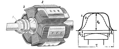
Fig. 4.2. The polar pole rotor Fig. 4.3. Distribution of magnetic induction
in the gap of the synchronous machine
Synchronous machines with pronounced poles are usually multipolar. They, as a rule, are calculated for small speeds of rotation. So, the hydro generator of Kuibyshevskaya HPP has 88 poles
(2p =88) and rotates with frequency n 1 =
68.3 rpm.
Hydrogenerators are always clearly polar. Since at low rotational frequencies n 1 (which develops a hydro turbine), hydrogenerators must produce electric power at an industrial frequency of 50 Hz, then they must have a large number of pole pairs:
Rotors of hydro generators have a large diameter (for placing poles) and a short length.
Turbogenerators are high-speed synchronous machines. This is explained by the high speed of rotation of steam turbines, the efficiency of which will increase with increasing rotational speed. Generally, turbogenerators are made bipolar (2 p =2) and have a speed of rotation n 1 =3000 rpm.
At such a large speed of rotation, the pole-pole design of the rotor is not suitable because of insufficient mechanical strength. Therefore, turbo-generators have an implicit-pole rotor-forged steel cylinder with profiled longitudinal grooves for packing the excitation winding (rice 4.4, b). Non-pole-pole rotors have a relatively small diameter with a considerable length.
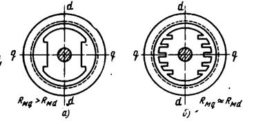
Fig. 4.4. Magnetic circuit of synchronous machine
In synchronous machines, two methods of excitation are used: electromagnetic excitationand excitation by permanent magnets.
Depending on the method of supplying the DC winding excitation independent excitation and self-excitation.
With independent excitation, a driver is used to obtain a direct current AT (see Figure 4.1), which is located on the same shaft with a synchronous machine and is a direct current generator whose power does not exceed the power of the synchronous machine.
During self-excitation, rectifiers are used to supply the excitation winding with a constant rectified current received from the generator.
In the case of excitation by permanent magnets, the rotor does not have an excitation winding, and its poles are a permanent magnet. This makes it possible to obtain a machine without contact rings, and, consequently, to increase its reliability and efficiency.
On the pole pieces of the pronounced poles of the rotor there are grooves in which the rods of a damper (soothing) short-circuited winding are executed, which is performed as a short-circuited winding of the rotor of asynchronous machines (see Figure 8.5, a). This winding serves to calm the rotor (reduce oscillations) in the generators, as well as for starting in synchronous motors.
Synchronous machines of low power are sometimes performed by reversed (by the type of DC machines). In such machines, the alternating current winding is located in the rotor slots and is led out to the three contact rings, and the excitation winding is placed on the clearly expressed poles of the stator. Powerful these machines are not made, because with such a design, a large alternating current (main current of the machine) must be passed through the contact rings at high voltage, whereas in conventional machines a small excitation current passes through the contact rings of the rotor at a voltage up to
440 V.
Synchronous motors of low power are very diverse in design.