If the electric motor does not work at all, it is necessary to check the electrical parts and the presence of the input voltage on them, ring the control circuit with a multimeter and evaluate the resistance of the windings. Most of the faults of electric motors occur in these electric nodes. Sometimes, due to short-term overloads, overcurrent protection may be triggered, knocking out an automaton in the control circuit (or simply blows out). If the control circuit is normal, then we proceed to checking the power section - these are different, closing contacts between the input voltage and the input terminals of the ED.
Repair of the ED usually ends with switching on the machine or replacing the fuse, less frequently replacing the starter. But sometimes the most important part of the ED can burn - internal winding. In standard operation mode, the ED winding heats up, but it manages to transfer heat to the electric machine case, but under overload conditions the temperature can rise significantly higher and cause damage to the dielectric insulation of the windings, and as a result, lead to inter-turn shorting or winding breakage.
In this case, the repair of ED passes the stage of replacing the burnt winding, which is a long and difficult process. In addition, when repairing and testing electric motors, attention should be paid to the mechanical parts and components of the device. After all, the banal drying of bearing lubricants increases friction resistance, load, heating, etc.
Several very simple and effective ways to test anchors, including their stators, can be tested. Manufacturing technology is as follows: We find an old electric pump "baby" in the attic in the free ads newspaper, then with a grinder we cut off both legs at the top at a 45-degree angle.

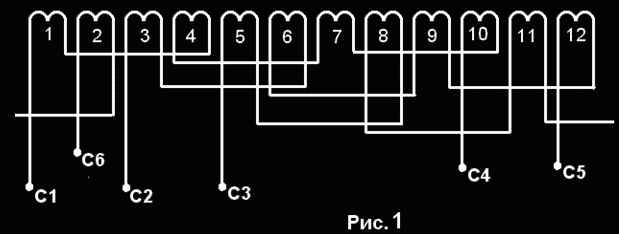
Simple methods for testing the windings of stators and rotors in electric motors of 3-phase current are considered.
Selection of electric motors for production mechanisms - Presents the characteristics of various types of electric motors for the most common mechanisms, as well as the method and calculation to ensure the specified performance, reliability and efficiency.
Repair of electric motors Tips for troubleshooting, organizing and conducting repairs and tests of various types of electric motors
Automatic measurement of engine output parameters
Electric motors are devices for converting electrical energy into mechanical energy and vice versa, but these are already generators. There is a huge variety of types of electric motors, therefore there is a great variety of motor control circuits. Consider some of them.
“Admitting our mistakes, we find the source of strength”
I decided to make a device for checking anchors on short-circuited turns and so on. It will be useful if you decide to repair the collector engine and check whether it is wound correctly. A very useful thing and when it was released in the USSR. But now in the afternoon with fire you will not find.
We will not go into complex formulas, I will try to explain in moments what I did. The article will break into 2 parts. "Part one. Magnetic. "Part two. Electricity". Then I will explain because of what 2 parts.
Part one. Magnetic.
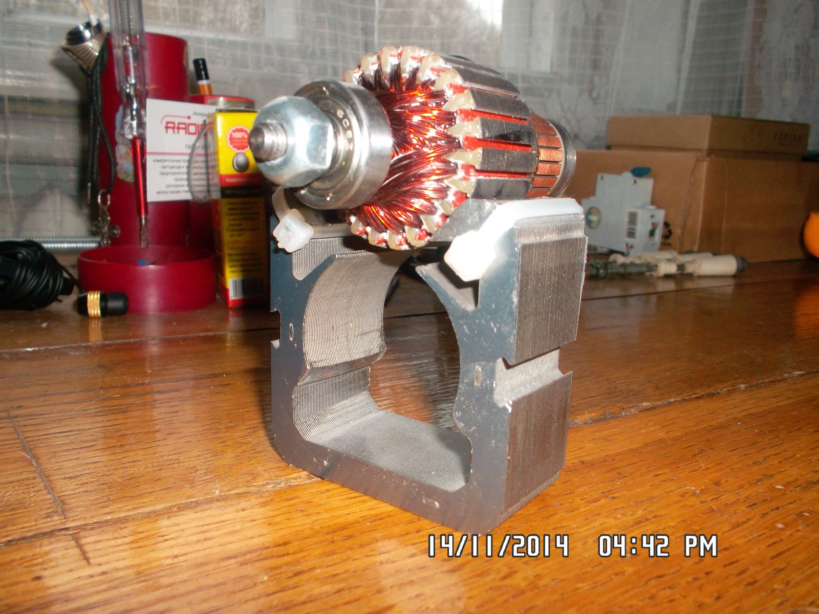
First we need a magnetic core, or otherwise - the stator from the engine of a vacuum cleaner. Then we need to cut a part at one side at an angle of 90 degrees, where the anchor itself will go to check. You can grinder, sawing, spoon - as whom it is more convenient.
 Then, we need to create a coil winding pad. Many people write that you need to take the electric cardboard, which is still a ton, but I don’t have it and it’s not planned for the next 50 kilometers in circumference. There is nowhere to buy. So an alternative is needed. Remember, when repairing engines of motorcycles and cars and there is no gasket - it was previously cut out from the folder “Case No.”. So we will do it, but we must bear in mind that the folder is rough, the cover of the notebook will also come down to us. I had a similar magnetic circuit and there was a cardboard, but a little bit more than necessary. But it's enough for us to measure the thickness and approximately pick it up. If only there was a layer between the wire and the stator itself.
P.S. The device on the stator of the vacuum cleaner, inspired by the theme in one forum. Original Thanks to the author for the push in the right direction.
Measure the thickness:
Electrical board from a different engine, but in which the windings once fit.
 and the cover of the notebook
 Now cut:
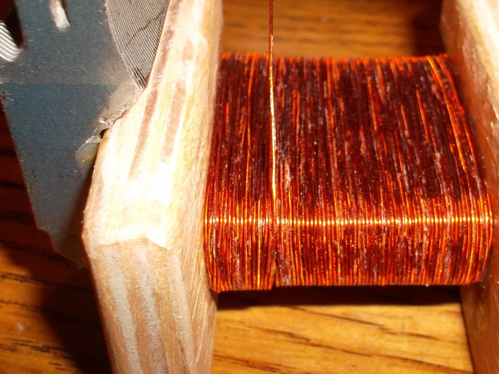
 And we wound in a single layer on the magnetic core, holding the whole thing together with adhesive tape:
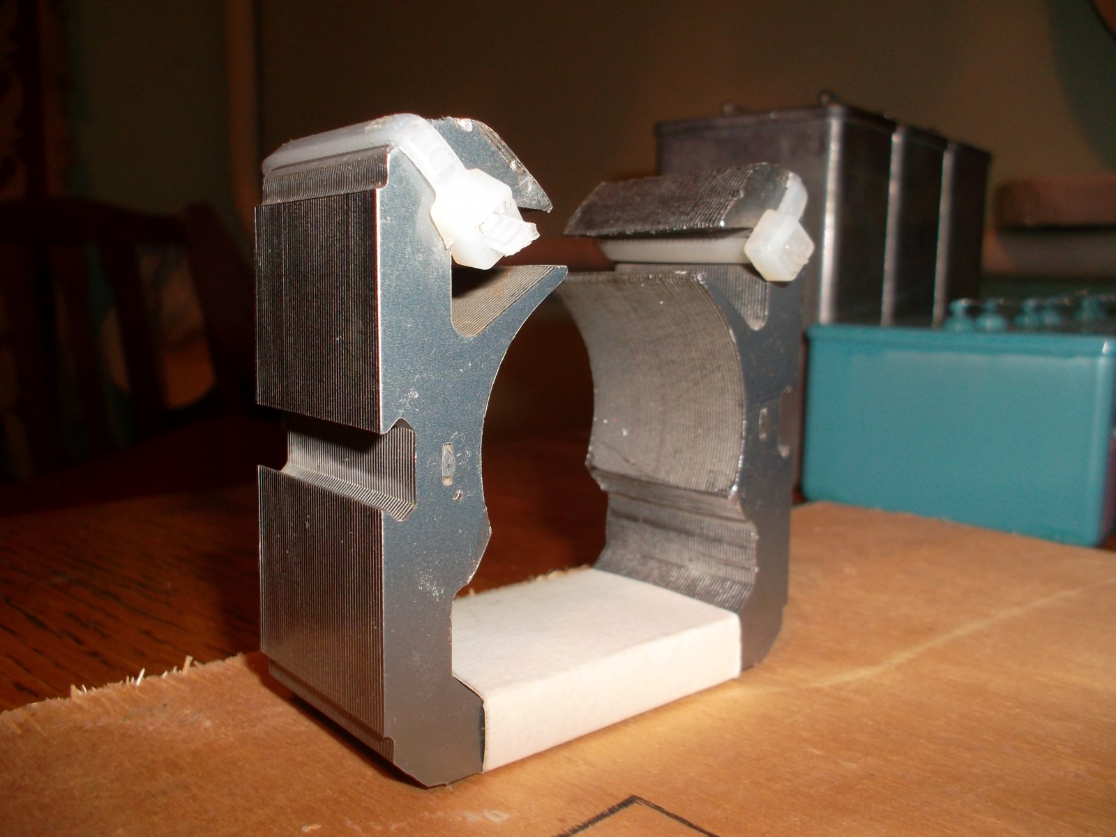
Then we need cheeks so that the wire rests on the sides and we have a full-fledged coil. Cut them out of plywood, having previously calculated the dimensions.

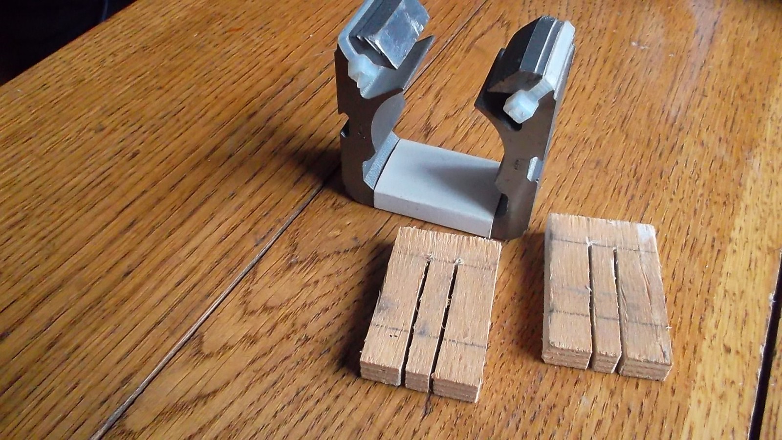
And choose a chisel too much. You can clean up a little sandpaper.


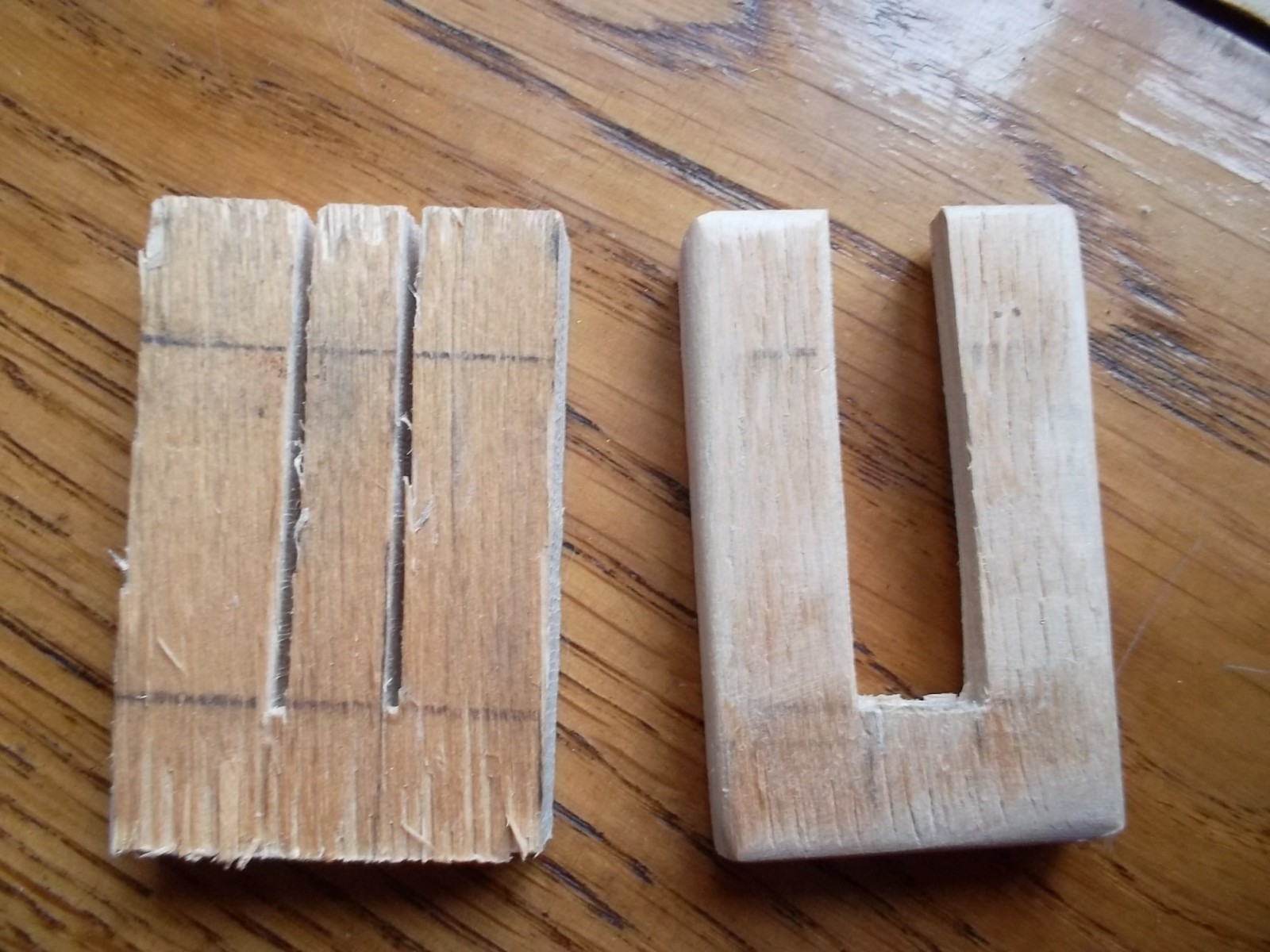
Do not forget to take into account the angle of the stator and adjust the same emery - a small angle on the cheeks themselves

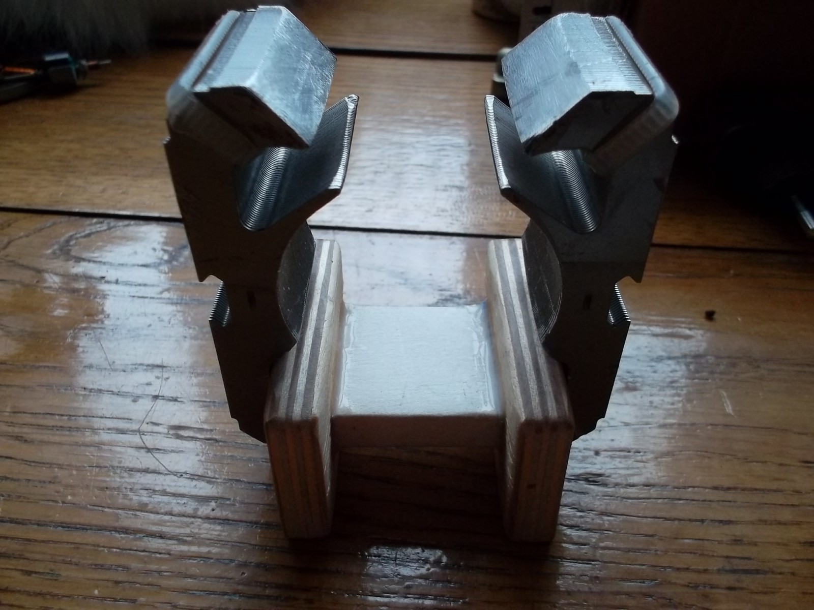
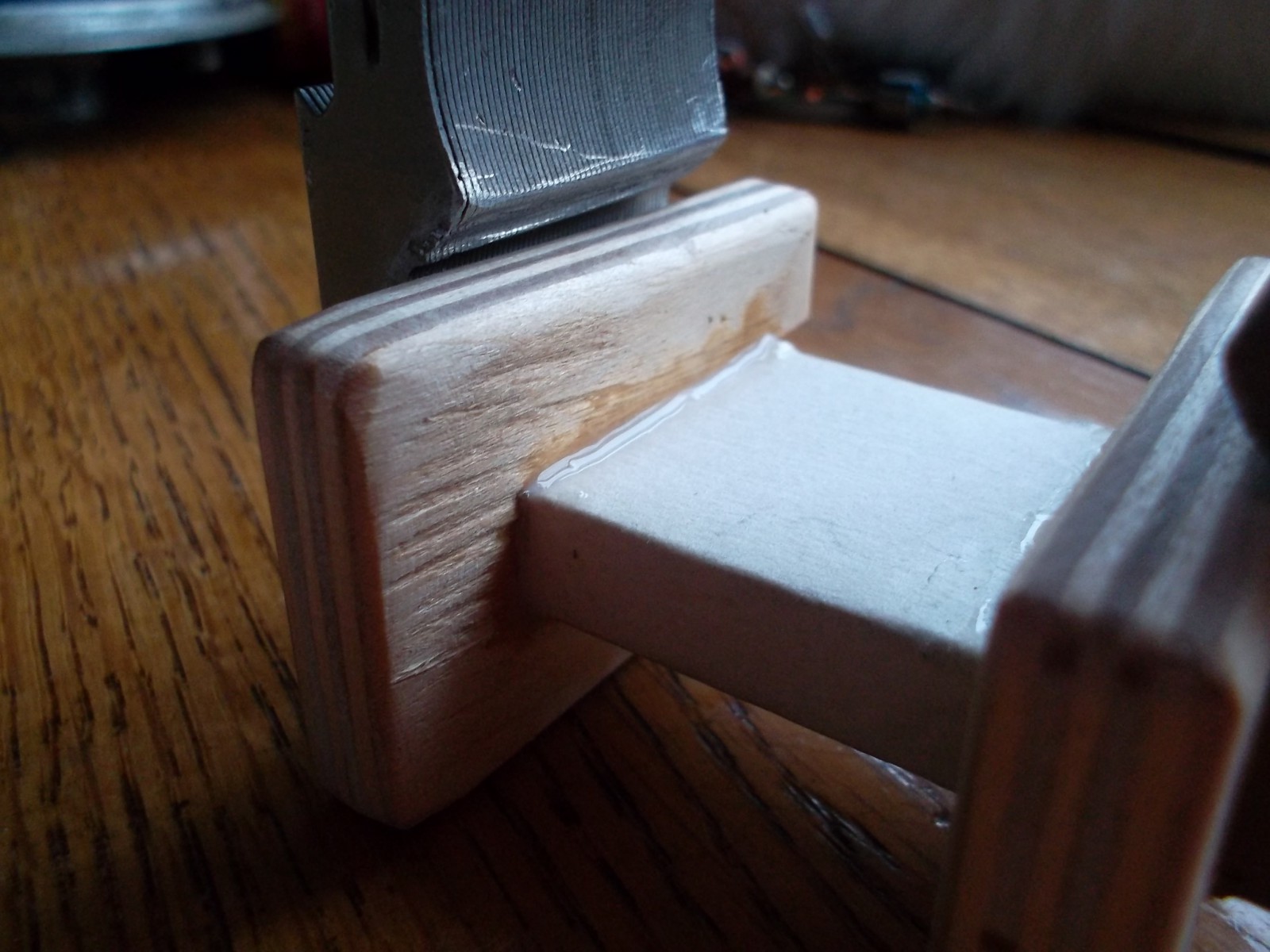
 It is desirable that the cheeks themselves become tight on the magnetic core.

If not, take a notebook and cut a piece of sheet to the size of the cheeks and wind it up with sizing. Until the wall becomes less tight.
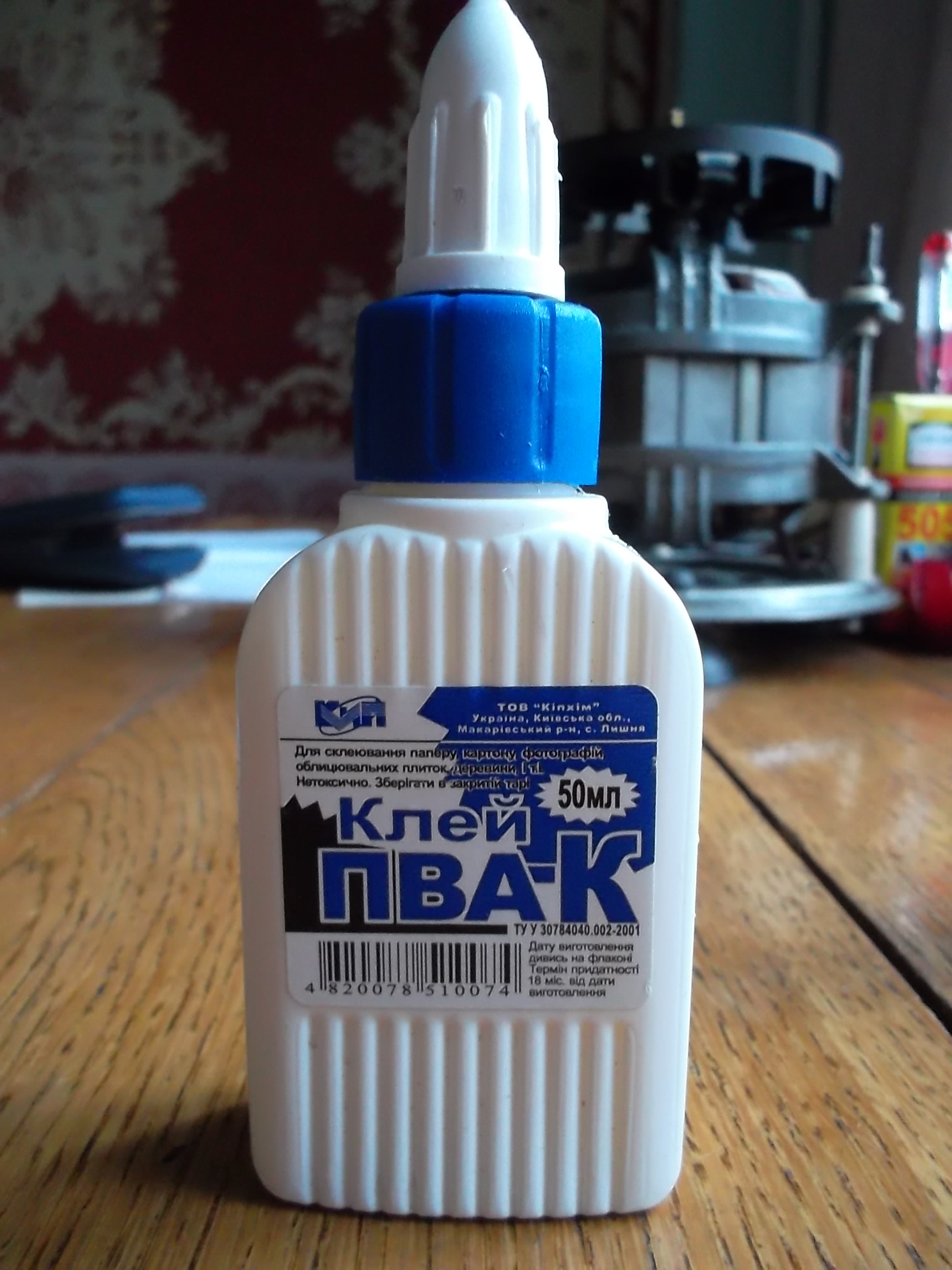
 We insert cheeks and glue with glue. I got almost half a pack of PvAk. Kleil and poured it about a dozen times. The next morning everything was ready.

 That's all part of the Magnetic.
Part two. Electricity.
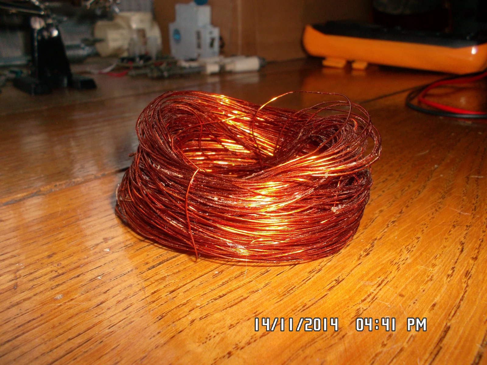
Let's start. We need a wire. I found in myself, once wound from the kinescope from the old TV wire. Immediately, the resistance seemed to me not sufficient - only 13 ohms, with a diameter of 0.4 for the length of the wire, as I then calculated 93m. 1 mm square copper wire withstands 3.2 -3.5 amperes. If we survive half, it will already be happiness, this should be enough for us. I thought so.
(According to the calculations (the number of turns = 50 / S * 220v) on this site, I calculated the necessary number of turns, it turned out 660. But I did not like that it applies to all thicknesses of wires! How is that ?? The site seems to be good, but in the calculations I I doubted something wrong.)
But then, I began to overcome vague doubts. Although I am not an electrician, all the same, as is known from Ohm’s law (here I = U \\ R) - if we supply 220 volts to a conductor with 13 ohm wire resistance, a current somewhere 16 A flows through it. where is 1.25A. In short, it just puffs and fades through the window. I thought and thought and wrote off the rest on the miraculous magnetic saturation of the core and the inductance (energy storage) of the coil itself, which I know little about, but decided to wind. In the end, the attempt is not torture. And any, albeit a failed attempt - a lesson for those who want to learn.
I wound about 4-5 hours. Turn to turn, diligently. Less and less faith in success. It turned out about 800 turns.

Finished, went to bed and left in the morning.
Today checked. I put the tester and ammeter in the desired modes for taking readings.
20 Volt - about 1 Ampere
50 Volts - 2 Amps
And risking, realizing that he was right yesterday - filed a hundred volts:
100 Volts - 4.5 Amps.
So what about 220 speech? She definitely "weathered", this wire.
Do not forget how much it should have been? Not more than 1.25A, and here 4.5A only at 100 Volts. The experiment was crowned with smoke from under the tape, melting the wire and complete failure. But it is better this way than to sit and look out the window with a drunken harey, thumping deeply.
And now about the Parts. Part of the "Magnetic" - fully suitable for implementation. But as for the part “Electricity” - I think the mistake here was that you need to increase the resistance - in other words, take so much wire to withstand 220 volts.
There is already a suitable donor, some old throttle from a TV with a resistance of 240 Ohms, a wire diameter of 0.08 mm. I think it will. Or maybe not. So to be continued.

The stator is a stationary part of an electric motor designed to create an electromagnetic field in which the rotor rotates (the moving part of the motor). Among the possible causes of a malfunction of the angle grinder - the UShM, "grinders" - is an open or short circuit of the windings (coil) of the stator.
Possible reasons
Factors causing a stator failure:
- power surge;
- water ingress;
- overload and overheating caused by it;
- sharp pulling the cord out of the socket.
Signs on which it is possible to understand that the stator is faulty:
- There is a smell of burning insulation.
- Overheated body.
- Smoke appears.
- The rotation of the shaft slows down or stops.
- The shaft spontaneously spins up, the tool is sharply gaining maximum speed.
Winding wires are covered with a protective layer of insulating varnish. When overheating, it burns and collapses. This causes a short circuit turns. Varnish emits a peculiar smell. The closure of only one of the wires completely disables the Bulgarian.
The rules that will help avoid overheating of the engine LBM:
- Turn off the device after working at low revs not immediately, but after about one minute.
- When working under load at low revs, take frequent breaks.
It is often possible to avoid replacing a defective stator by winding its winding. The rewinding of the spoiled stator coil of the grinder can be done by hand, but it is recommended to assign this work to a specialist.
Disassembly of the grinder
How to check the stator of the angle grinder (grinder)? You need to start with disassembling the device. To perform the work you will need a screwdriver.
Procedure:
- Remove from the surface on which the Bulgarian will be disassembled, all unnecessary details.
- Remove the work disk.
- Remove the screw that secures the cover.
- Remove the screws holding the plate.
- Slide the cover towards the cord.
Main details of the UShM electric motor:
- rotor (anchor);
- stator;
- collector;
- brushes.

The stator is located on the outside of the engine, on top of the rotor. To get the stator, you first have to take out the brushes, then remove the gearbox and after that pull the anchor out of the grinder body. Remove the rotor from the stator before testing. Inspection is recommended in bright light. First of all, you need to carefully examine the winding and make sure that there are no visible breaks on it. If the inspection did not reveal the cause of the stator malfunction, then a special device will be needed for testing.
Check indicator short circuit
It is possible to detect a winding break or short circuit in it using the indicator of short-circuited turns (IR). Other names - the indicator of the interturn circuit or the indicator of the defects of the windings of electrical machines.
The device consists of:
- power supply;
- enclosures with LCD display, accessory sockets;
- connecting wires;
- large induction sensor;
- small induction sensor.
The principle of the indicator is based on the induction of a pulsed electromotive force in the tested winding. In the presence of short-circuited coils, a magnetic field pulse is recorded from the short-circuit current flowing through them.
The procedure for checking the stator of the Bulgarian device IDVI:
- Inspect the interturn circuit indicator. Make sure that there are no external damages, integrity of the connecting wires and sensors.
- Connect the power supply.
- Press the power button and make sure that the device is working.
- If the indicator of winding defects has been in the cold for a long time, then it should be kept at room temperature for at least 2 hours.
- Disconnect power to the angle grinder.
- Choose from two sensors large or small depending on the size of the stator.
- If in the passport of the angle grinder the nominal voltage per one winding turnout is not indicated, it should be determined by the formula: the nominal voltage of the entire coil divided by the number of turns.
- Turn on the device.
- To establish on the indicator the largest amplitude of the pulse test voltage, obtained during the calculation, than the one obtained during the calculation.
- Pressing the sensor to the surface of the winding, consistently check all the grooves, waiting for 3-4 s. If a short circuit is detected, the device will beep, and the corresponding inscription will appear on the display.
- If short-circuited coils are not detected, then install the next (larger) amplitude on the device and make sure that there is a winding insulation margin.
- Turn off the device.
The indicator of defects in the winding can check the insulation condition between the stator and rotor coils, as well as between the stator winding and the grinder body. If it is not possible to buy a finished device, then a simpler indicator of short-circuited coils can be made independently.
Multimeter check
 You can make sure that the stator is working with the help of a device - a multimeter. This is a universal measuring device. They can measure several electrical quantities: voltage, amperage, resistance. The device consists of a case on which there is a display, a switch and sockets, and two cords with probes (positive and negative). The negative probe is always connected to the lower socket, and the positive one - to the middle or upper, depending on the current strength in the device being tested.
To check the stator of the grinder (Bulgarian) it is necessary to set the resistance value on the multimeter from 20 to 200 Ohm and alternately bring the gauges of the measuring device to the windings. If the resistance everywhere has the same magnitude, then the coil is normal. If the device shows another resistance at some points, then there is a short circuit or breakage of one of the turns in the winding. The same principle is used to test the stator with an ohmmeter. Its difference from the multimeter lies only in the fact that this device can measure only the resistance.
Device for checking anchors and stators of electrical machines
Another device with which you can check the Bulgarian stator - a device for checking anchors and stators of electric machines PUNS 5. The device has light and sound alarms, allows you to detect the interturn winding short circuit, break, measure the insulation resistance of the coils.
The device operates in two modes - “anchor” and “stator”. Mode change occurs with the switch. The device is equipped with a convenient device for installing and fixing the checked engine. It consists of two legs attached to the shaft. The legs move freely along the shaft, which allows you to change the distance between them and check the engines of different sizes. Check is carried out with the help of two probes. The presence of an open or short circuit on the stator winding is indicated by special red LEDs and a sound signal. The verification procedure is described in more detail in the instrument manual.
Conclusion
Thoroughly checking the stator of the angle grinder is relatively easy. But this can be done only using special devices. Therefore, if a visual inspection confirms that the cause of the malfunction of the grinder is a damaged stator, further inspection and repairs are best done in a specialized workshop.