Battery charge
Rechargeable batteries are charged with a constant (rectified) current at charging stations located in specially equipped premises of service points.
Rechargeable batteries are charged when they are brought into working condition, during the control and training cycle (CTC), as well as periodically during operation and at discharges below the permissible limits. The charging process makes it possible to control and improve the technical condition of both individual batteries and the batteries as a whole.
Rechargeable batteries entering the charging station are pre-cleaned of dust and dirt, and their pole leads are removed from oxides.
Preparation for charging at the charging station is carried out in the following sequence:
An external examination determines the condition of the monoblock, the battery cover and the pole terminals;
Measured electrolyte density in all batteries of each battery. In batteries, where the level is insufficient for the electrolyte in the hydrometer, the density of the electrolytedetermined during battery charging;
The level of electrolyte in each battery is checked and brought to the operating rate by topping up with distilled water (but not electrolyte!).
At charging stations, rechargeable batteries, brought into working condition, as well as those taken from cars, are charged, as a rule, with a constant value of charging current.
With this method, the magnitude of the charging current throughout the entire charge time is maintained unchanged. This is achieved by changing the resistance of the rheostat connected in series with the battery, changing the voltage of the current source or using automatic current regulators.
As current sources, DC generators, converters or rectifiers are used. To achieve 100% battery charge, a charger voltage of at least 2.7 V is required for each rechargeable battery.
The positive pole of the battery is connected to the positive pole of the charging current source, and the negative to the negative.
The magnitude of the charging current is set to 10% of the nominal battery capacity, i.e. 19 A for a 6CT-190 type battery.
During charging, the density of the electrolyte in batteries gradually increases and only at the end of the charge takes a constant value. The voltage on the batteries slowly increases to 2.4 V, at which the decomposition of water begins and the gas discharge that is noticeable by eye. Gas is released on the surface of the electrolyte in the form of bubbles. The battery voltage at the end of the charge reaches a value of 2.6-2.65 V, after which it no longer increases. At the same time, gas release becomes abundant, creating the impression of a “boil”.
In all cases, the charge of the batteries must be carried out until the voltage on the batteries and the density of the electrolyte are constant for 1 hour while simultaneously producing a large amount of gas (“boiling”) in all the batteries of the battery.
The temperature of the electrolyte during charging of the batteries increases, so it is necessary to control its value, especially towards the end of the charge. The temperature of the electrolyte during charging should not exceed 45 ° C. If the temperature is higher than 45 ° C, the charging current should be reduced by half or the charge should be interrupted for the time required for cooling the electrolyte to 30-35 ° C.
Measurement of the battery voltage, density and temperature of the electrolyte in the charging process should be carried out at the beginning of the charge - every 2-3 hours, and at the end of the charge - every hour. If by the end of the charge lagging batteries are detected, the electrolyte density and voltage are lower than that of other batteries, then in order to avoid unnecessary recharging of the entire battery, as well as excessive waste of electricity, you should charge them separately. To do this, connect the wires from the charging unit to the jumpers of the lagging battery with clips and continue charging at the same charging current. The charge continues until all signs of its termination appear. After that, the electrolyte density in the lagging accumulator is adjusted to the required value.
At the end of the charge, the electrolyte density, reduced to 25 ° C, should be within the normal range indicated in Table. 7.13. If the final electrolyte density differs from the norm or the difference in densities in the batteries of one battery is more than 0.01 g / cm 3, it is necessary to adjust the density of the electrolyte by topping up distilled water in cases where the density is above the norm, or by adding sulfuric acid to a density of 1.40 g / cm 3 when it is below normal. Before topping up part of the electrolyte from the battery is selected with a pear. Density debugging should be carried out only at the end of the charge, when the density of the electrolyte no longer increases, and due to “boiling”, rapid and complete mixing is ensured.
Correction of the electrolyte density improves the performance of the battery and makes it possible to correctly determine the degree of charge of the battery in operation by the density of the electrolyte. Adjustments must be made very carefully. If at one time to bring the density of the electrolyte to the norm fails, the adjustment should be repeated.
Density adjustment operations are recommended in the following sequence:
At the end of the charge, measure and record the temperature of the electrolyte in the average battery;
Measure alternately the electrolyte density in each battery, find the temperature correction and determine the nature of the adjustment (decrease or increase in density) and its value;
Without stopping the charge of the battery, select a portion of the electrolyte from the batteries and add distilled water or an acid solution of 1.40 g / cm 3 density to them;
Continue charging the battery for 30-40 minutes, after which again measure the density of the electrolyte in the batteries where the adjustment was made, and if the density of the electrolyte, reduced to a temperature of 25 ° C, will be different from the norm, repeat the adjustment.
The operating level of the electrolyte above the upper edge of the electrodes is set after the end of the density correction and the batteries off the charge. The exposure time of the batteries to idle before setting the level should be 30 minutes. When the electrolyte level is below the norm, the electrolyte must be added to the battery of the same density; when the electrolyte level is above the norm, the excess electrolyte should be collected with a pear.
Terms of use
You should handle the batteries carefully, to avoid mechanical shocks and vibrations, as the case and the active mass of the battery have low mechanical strength. Due to the large mass of the battery, special care is required when carrying it, removing it from the machine and installing it on the machine. Before removing the batteries and before installing them on the machine, the battery switch must be turned off. It is necessary to prepare the engine for start-up and use the starter in strict accordance with the instruction manual of the machine.
Fig. 7.110. The switch "mass" 1400.3737
7.13.2.2. Battery Switch (ground)
The switch (Fig. 7.110) is designed to disconnect the batteries from the car body during long-term parking, removal and installation of electrical apparatus and appliances.
The switch has the following device. In the housing 12 in the plastic bushings installed clamps 14, which are attached to the wires from the battery and the car body. Electromagnet 4 is fastened to the case with three screws. The winding of the electromagnet is connected to the battery using a button located in the driver's cabin. A pusher 9 is screwed into the core 8 and abuts against the stem 3 of the locking device. By changing the length of the pusher, the precise actuation of the locking device is adjusted. On the rod 3 is fixed spring-loaded contact plates 1 and 2. The ball retainer 10 and the pawl 11 serve to hold the contacts in the closed position. Button 6, closed with a rubber cover 5, serves to mechanically control the switch.
Works battery switch as follows. When connecting the electromagnet winding 4 to the battery, the core 8, overcoming the force of the return spring 7, is pulled in by the electromagnet and the pusher 9 moves the rod 3. The contact plate 1, and then 2 connect the clamps 14 to each other. The ball retainer 10 enters the recess of the pawl 11, which ensures the retention of the contacts in a closed state. When the driver releases the button, under the action of the return spring 7, the core and the pusher return to their original position. To disconnect the battery, the driver must press the button for the remote control of the battery switch again. In this case, the core retracts and pushes the upper lever of the pawl 11. The ball lock 10 is released, and under the action of two springs 13 the contact plates 1 and 2 open the battery circuit. The use of the contact plate 1 significantly reduces the erosion of the main contact plates 2.
In order to prevent disconnection of the batteries from the body of the KamAZ 6560 when the engine is running using the remote mass switch, there is an interlock switch on the cars. It works as follows: after turning the key switch devices and starter (VPS) in the first position of the electric current from the terminal "KZ" VPS through the fuse on the 10 A block F3 enters the relay coil K3, which leads to the opening of the relay contacts between its terminals "30" and "88", consequently, to the impossibility of connecting the winding of the electromagnet of the "mass" switch K17 to rechargeable batteries.
7.13.2.3. Generator set
The generator set is designed to supply all consumers of a car with 6560 electric energy while the engine is running and to maintain the voltage in the vehicle’s electrical system to within (28.4 ± 0.6) V.
The generator set is a generator of model 3122.3771 with a built-in voltage regulator (of the type JA120M12I).
The generator set is located in the upper front part of the engine and is attached with two paws to the bracket, and the third one is attached to the tensioning strip with a poly V-belt.
Technical characteristics of the generator set
Rated voltage, V 28.
Maximum load current, A 80.
The frequency of rotation of the rotor, in which the generator voltage reaches 26 V:
When the load current is 10 A - no more than 1300 min -1;
When the load current is 30 A - no more than 1550 min -1;
When the load current is 60 A - no more than 2200 min -1.
Load current at a voltage of 26 V and a rotor speed of 3500 min -1, not less than 75 A. At the same time, the voltage at the output "W" must be at least 17 V, the voltage at the output "+ D" should be no less than the "+" output.
Adjustable voltage at an ambient temperature of (25 ± 10) ° C, rotor speed of 5000 min -1 and load current of 27 A with a connected battery with a charge level not lower than 75% or with a connected load equivalent to the battery in terms of filtering properties be (28,4 ± 0,6) V.
Generator set It is a three-phase twelve-pole synchronous electric machine with a built-in rectifier unit, a noise-suppressing capacitor, a brush holder with a voltage regulator and a system with draw ventilation.
The generator set has the following conclusions:
"+" - to connect with the battery and the load;
"W" or "AT" - for connection with starter and instrument switch;
"W" or "~" - phase output for connection to the tachometer and starter lock relay;
"+ D" or "D" - output from additional diodes to connect with a test lamp.
The generator set (fig. 7.111) consists of a stator 2, a rotor 5, a lid on the side of slip rings 8 with a rectifier unit and a brush holder with a voltage regulator 1, a lid on the drive side 7, a pulley 4, a fan 6.

Fig. 7.111. Generator set:1 - brush holder with a voltage regulator; 2 - stator; 3 - the bearing from the drive; 4 - pulley; 5 - the rotor; 6 - fan; 7 - a cover from the drive; 8 - cover from the side of slip rings; 9 - coupling screws
The stator consists of a core and a winding. The core is made up of electrical steel plates, insulated from each other with varnish and connected by welding on the outer surface of the package. Inside the core, 36 slots are uniformly distributed around the circumference, designed to accommodate the windings.
The stator winding is three-phase, connected in a triangle. Such a connection allows to reduce the current in the winding and, therefore, to use a thinner wire. Each phase consists of series-connected coils wound with enamel insulated wire. The coils are fixed in the stator core with textolite wedges. The terminals of the phase windings are attached to the terminals of the rectifier device. The output of one of the phases "W" is used to connect the starter and tachometer blocking relays.
The rotor is an inductor and consists of a shaft, an excitation winding, pole pieces, slip rings. The steel shaft, on its corrugated surface rigidly, by pressing, fixed steel sleeve, pole pieces and slip rings. Pole tips are made of mild steel, have six pointed beaks, which form six pairs of poles.
The field winding is wound on a steel sleeve. The winding is insulated from the sleeve and pole ends with a polyethylene frame and cardboard washers. The ends of the excitation winding are soldered to contact rings located on the insulating sleeve. To reduce the load on the bearings, the rotor is dynamically balanced by over-drilling the holes on the pole pieces.
The lid on the side of the contact rings is made of aluminum alloy, it has ventilation windows and a generator mounting paw on the engine.
The cover is installed:
A rectifier unit (used for full-wave rectification of three-phase current) with three additional diodes designed to power the excitation circuit;
Plastic brush holder with a voltage regulator, mounted on the cover with two screws;
Interference suppression capacitor mounted on top of the cover;
Connecting block with output from additional diodes;
Phase output
The lid on the drive side is made of aluminum alloy, has ventilation windows and two paws, one of which serves to fasten the generator to the engine bracket and the other with a threaded hole M8 to attach the tension bar.
The fan and pulley are mounted on the generator shaft and secured with a nut with a spring washer.
In the generator covers are installed sealed ball bearings of the rotor shaft with one-time lubrication. During operation, no need to add lubricant. The ball bearing placed on the shaft from the drive side is fixed against axial movement. In the lid on the side of the contact rings, the outer ring has a sliding fit that relieves the bearing from axial forces.
The generator is waterproof, so the car KAMAZ 6560 can overcome the ford without damaging the generator. After exiting the water, the generator should be operational. The waterproof performance of the generator is ensured by applying appropriate coatings to the surface of its parts and impregnating the windings with waterproof varnishes.
The principle of the generator
When the instrument switch and starter are turned on, the voltage from the battery is applied to the field winding (through brushes and slip rings) placed on the rotating part of the generator - the rotor. Around the excitation winding creates a magnetic field, which, passing through the pole tips, forms the north and south poles on the rotor. When the rotor rotates, the magnetic field will rotate, which, crossing the stator windings, will induce an emf in them. Considering that poles of different polarity alternately pass under each stator winding, then the EMF induced in the stator windings will be variable, of the same frequency, but shifted in phase by 120 °.
The rectifier unit converts the alternating voltage into a constant voltage, and when it becomes greater than the battery voltage, the generator will begin to power the consumers and charge the battery. The excitation winding will also be powered from the generator through additional diodes.
With an increase in the rotor speed, the generator voltage can reach a dangerous value for the receivers, so the generator works in conjunction with a voltage regulator that maintains the voltage in the vehicle’s on-board network within the specified limits.
The principle of the voltage regulator
The voltage of the generator is determined by three factors - the rotor speed, the amperage delivered by the generator to the load, and the magnitude of the magnetic flux created by the field current. The higher the rotor speed and less load on the generator, the higher the generator voltage. An increase in the current in the field winding increases the magnetic flux and with it the voltage of the generator; a decrease in excitation current reduces voltage.
The voltage regulator stabilizes the voltage by varying the excitation current. If the voltage increases or decreases, the regulator respectively reduces or increases the excitation current and enters the voltage within the desired limits. The regulator contains a measuring element, a comparison element and a regulating element.
The sensitive element of the electronic voltage regulator is the input voltage divider. From the input divider voltage is supplied to the reference element, where the role of the reference quantity is played by the stabilization voltage of the Zener diode. The Zener diode does not pass a current through itself at a voltage below the stabilization voltage and breaks through, that is, it begins to pass a current through itself if the voltage on it exceeds the stabilization voltage. The current through the Zener diode includes an electronic relay that commutes the excitation circuit in such a way that the current in the excitation winding changes in the right direction.
The work of the generator set of the car KAMAZ 6560
In fig. 7.112 shows an electrical diagram of the connection of the generator set to the power supply system (see. Fig. 7.106).
After turning on the device switch and starter in the first position, the terminals are closed between themselves "AM" and "KZ".Electric current from the battery through the 60 A fuse, through the normally closed contacts of the excitation winding trip relay (ROOV) is fed to the output “W” generator that is associated with the output "AT" voltage regulator, which leads to the opening of the power transistor VT2 (Fig. 7.113). At the same time, the electric current flows through a 8 A block fuse F3 (see fig.7.112) in the winding of the relay switch "mass" (RVM). Its contacts are closed, and the electric current flows through the initial excitation circuit of the generator: from the battery through a 60 A fuse, through the control lamp of the battery discharge (CL), which turns on, to the output "+ D" generator and further to the excitation winding of the generator, to the terminal "W" voltage regulator and through the open power transistor VT2 (see. Fig. 7.113) to "ground".
Thus, the excitation winding of the generator is connected to the on-board network and then the generator operates as described above (see the principle of the generator). After the generator began to generate electrical energy, the voltage at the output "+ D" the generator becomes equal to the voltage at the output of the "+" generator, therefore, the current in the circuit of the initial excitation of the generator disappears and the control lamp turns off, and the excitation windingbegins to be powered by a block of additional diodes. With an increase in the frequency of rotation of the generator rotor, a voltage regulator comes into operation.

Fig. 7.112. Electrical circuit of the generator in the electrical system
ROOV is designed to prevent excitation of the generator when using an electric torch device (EFF).
The reason for this is that the electrostatic plugs are designed for a voltage of 19 V, therefore, after the engine is started using an electro-electric torch, if the generator starts to generate electrical energy, the plugs will fail.
The switch for the ground switch has two functions. The first is to disconnect the battery switch button chain after turning on the VPC, in order to exclude the possibility of disconnecting the batteries from the on-board network while the engine is running (not shown in Fig. 7.112). The second is to turn on the initial excitation circuit of the generator. This was done to relieve the PRT contacts, since the current during initial excitation of the generator can reach 5 A. On the KAMAZ car, the instrument switch and starter switch only the RVM winding circuit and the voltage regulator control circuit, where the current is fractions of amperes.
The control lamp has a diagnostic function. After turning on the PRT, it is in the on state and signals the condition of the initial generator excitation circuit. After starting the engine, it should turn off if this does not happen, or the lamp is turned on while driving - this indicates that the generator for some reason does not produce electrical energy.
The operation of the voltage regulator. As noted above, when the VPS is turned on in the first position, an electrical current is applied to the output "AT" voltage regulator (see. Fig. 7.113) and through a resistor R4 enters the base transistor circuit VT2, which leads to its discovery. In this case, the excitation winding of the generator is connected to the power circuit through the transition emitter-collector of the transistor VT2. Voltage to composite Zener diode Vd1 supplied from the block of additional diodes of the generator through the terminal "D" voltage regulator and voltage divider on resistors R1, R2. While the generator voltage is low and at the Zener diode it is lower than the stabilization voltage, the Zener diode is closed, the current through it, and hence in the base transistor VT1 not flowing, transistor VT1 is closed.
If the voltage at the "+" output of the generator has increased, for example, due to an increase in the rotational speed of its rotor, it also increases at the output from the block of additional diodes, and hence at the zener diode Vd1. When this voltage reaches the value of the stabilization voltage zener diode Vd1breaks through, the current through it begins to flow into the base circuit of the transistor VT1which opens with its transition emitter-collector short-circuits the output of the transistor base VT2 to "mass". Transistor VT2 closes, breaking the excitation winding supply circuit.
The excitation current decreases, the voltage of the generator decreases, the zener diode closes Vd1 and transistor VT1transistor opens VT2, the excitation winding is switched on again in the supply circuit, the generator voltage rises, and so on, the process repeats.
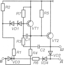
Fig. 7.113. The electrical circuit of the integrated controller type H120M1
Thus, the adjustment of the generator voltage by the regulator is carried out discretely - by changing the relative time of activation of the excitation winding in the power circuit. If the frequency of rotation of the generator rotor has increased or its load has decreased, then the time of activation of the excitation winding decreases, if the frequency of rotation has decreased or the load has increased, it increases.
Diode Vd2when closing the transistor VT2 prevents dangerous voltage spikes due to the excitation of the excitation winding circuit, which has significant inductance.
In this case, the excitation winding current can be closed through this diode, and no dangerous voltage spikes occur. Therefore, the diode Vd2 called extinguishing. Resistance R3 is resistance to tight feedback. When you open the transistor VT2 it is connected in parallel to the resistance R2 voltage divider. In this case, the voltage on the Zener diode Vd2 decreases sharply, which accelerates the switching of the regulator circuit and increases the frequency of this switch. This has a positive effect on the quality of the voltage of the generator set. Capacitor C1 is a kind of filter that protects the regulator from the influence of voltage pulses at its input.
Rules of operation of the power supply system
1. It is impossible to press the button of inclusion of the electroflight device at the working engine in order to avoid failure of a regulator of tension.
2. When the vehicle is parked, it is necessary to disconnect the batteries from the electrical system by pressing the button of the remote battery switch. The button must be pressed briefly (no more than 2 s).
3. Do not disconnect the battery with the battery switch when the engine is running.
4. When carrying out electric welding work on the vehicle, the batteries must be disconnected by a remote switch and the wires from the “+” and "Ш" ("В")generator. The ground wire of the welding machine must be connected in the immediate vicinity of the weld.
5. Do not connect and disconnect the plug connectors and the positive output of the generator when the engine is running and the batteries are turned on, and the engine must not be started when the positive lead of the generator is disconnected.
6. It is not necessary to check the serviceability of the generator by shorting the "+" terminals or "W" ("B")jumpers to ground and between themselves.
7. No need to connect output "Ш" ("В")brush holder with the conclusion "+". This leads to failure of the voltage regulator.
8. It is impossible to check the serviceability of the electrical equipment circuit and the individual wires with a megger meter or a lamp to which voltage is applied above 26 V, with the generator disconnected.
9. It is not necessary to check the rectifier unit from a DC source with voltage more than 24 V, from an AC source, and also without a signal device connected in series with the rectifier unit.
10. In order to avoid failure of the voltage regulator when recharging the batteries from an external source, it is necessary to disconnect the batteries from the vehicle network.
7.13.3. Start-up and pre-launch preparation system
The system for starting and pre-launch preparation of a KAMAZ 6560 vehicle includes an electric start system, an electric torch device and a preheater.
The electric start system is designed to turn the engine crankshaft at the frequency required for starting.
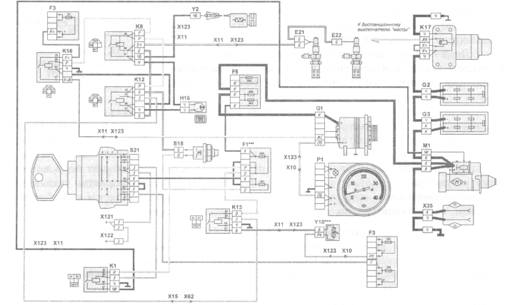
Fig. 7.114. Starting circuitry
The main elements of the electric start system are (Fig. 7.114):
Starter ST142B2 M1;
Starter control equipment (instrument switch and starter with anti-theft device 1902.3704 TU37-301.010-93 S21, starter relay 738.3747-20 TU37-309.023-97 K1);
The source of electrical energy (two batteries 6ST-190AP (G2, G3),connected in series);
PS315 external start socket X35;
Connecting wires
The system works as follows: when turning the key of the instrument switch and the starter to the second non-fixed position, its outputs are closed "30" and "50" and the coil of the starter relay is connected to the battery, as a result of which the current flows through the following circuit: “+” of the battery (see fig. 7.106) - through a 60 A fuse - terminal "30" switch devices and starter (VPS) - terminal "50" PRT (see fig. 7.114) - starter relay winding K1 - by wire to the car body - then to the negative output of the battery.
The contacts of the starter relay closes the circuit of the windings of the starter relay. In this case, the current path is the following: "+" battery - ... - through a 60 A fuse (see. Fig. 7.114) - closed contacts of the starter relay K1 - the engaging and holding windings of the traction relay of the starter M1 - further along two parallel branches: first - ... - holding winding - traction relay case - starter motor case - wire - car case - negative battery terminal; the second - ... - retractor winding - connecting busbar - excitation winding of the starter motor - armature winding of the starter motor - negative brushes - starter motor housing - wire - car body - negative battery terminal.
When current flows through the windings of the traction relay, the anchor of the relay retracts and introduces the drive gear into engagement with the gear ring of the flywheel. After the gear has been fully inserted into contact, the contact disk of the traction relay closes the power contacts between them, and the starter motor is connected to the battery voltage and the engine crankshaft starts to turn.
After the engine starts to work steadily, the driver should immediately release the UPU key, which will turn off the starter.
7.13.4. Lighting system
The lighting system is divided into the system of indoor and outdoor lighting.
7.13.4.1. Indoor lighting system
The system is designed to illuminate the driver's workplace, instrumentation, cargo platform of the car.
The main elements of the interior lighting system are (Fig. 7.115): cockpit ceiling lights ( E14, E15), glove box E18, berth E19; engine compartment lamp E27; portable lamp socket X31; instrument lighting lamps ( P1 - P4) and switches ( S9 - S12, S31); block fuses F2 and F3; cab light switches (S10, S31);dashboard panel lighting switch with rheostat R1.
Consumers of the interior lighting system are connected to the on-board network in such a way that electrical energy flows to them, bypassing the instrument and starter switches. All circuits are protected by 10 A fuse blocks. F2 and F3 type PR112.
Ceiling lighting cabins P 1.3714010 are designed to illuminate the driver's workplace. They are installed on the cab roof from the inside, and their switches 3842.3710-02.09 on the instrument panel panel (see Fig. 6.8, items 1, 2).

Fig. 7.115. Interior lighting scheme
When two switches are turned on simultaneously, the cabin illumination will be determined by the brightness of the more powerful lamp. Also when turning on the lamps the control lamp of the corresponding switch is turned on. S10 or S31. The current at the same time arrives at the lamp, bypassing the switch resistor, and the lamp shines with full heat.
Portable lamp socket X31 (see fig. 7.115) type 47K is installed on the left panel of the cabin. The socket is connected through a single-pin connector X7 to fuse box F3 and through a 10 A fuse to the source of electrical energy. The second outlet of the outlet with a separate wire is connected to the body of the Kamaz 6560 car.
Commander's socket X34 Type 47K installed on the right panel of the cabin.
The engine compartment lamp model PD308-B-0 (Fig. 7.116) is installed under the floor of the cab and is designed to illuminate the engine and attachments for maintenance and repair. It consists of a housing with a cartridge 2 lamp 1 type A24-21 and a reflector 4, which has the ability to rotate, changing the direction of the light beam, the switch 3 mounted on the lamp body.
Underhood lamp connected via a 10 A fuse block fuse F2 (see fig. 7.115) to the source of electrical energy.
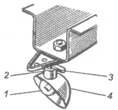
Fig. 7.116. Engine compartment lamp

Fig. 7.117. Glove compartment hood
The ceiling of the glove box PK142-B (fig. 7.117), installed in the glove box in the cab of the KamAZ 6560, is designed to illuminate it. Switching on and off the ceiling is carried out by a switch 1, mounted in a plastic transparent body 2 of the ceiling. In the glove compartment of the glovebox is used a spotlight lamp 3 type AC24-5. Connecting the glove compartment to the onboard network is similar to connecting the engine compartment lamp (see. Fig. 7.115).
Sleeping light E19 by design and connection is similar to the glove compartment cover.
Instrument Lighting Switch R1designed to turn on the instrument lighting lamps and control their luminous intensity, is installed on the instrument panel panel (see Fig. 6.6, pos. 11).
The instrument panel panel lights are turned on when the center light switch is turned on. S7(see Fig. 7.115) to the first position (marked “0" in Fig. 7.115) when the front and rear position lamps are turned on. All the instrument and switch lighting lamps are connected in parallel with each other and the current source, which ensures the same luminance brightness and prevents open circuit when one of the lamps burns out.
Negative conclusions of the consumers of the system are connected to the total "mass" of the Kamaz car 6560 with separate wires.
Switch Lamps ( S9 - S12, S31) shine incomplete heat, since the current is supplied to them through the resistors of the switches. The lamp in the switch shines with full heat only when the consumer connected to it is turned on. Each switch also has two diodes, which prevent connection between the lighting circuits of the instrument panel panel and the circuit activated by this switch.
Installed on the engine alternator G-272, which is a three-phase 12-pole synchronous electric machine with direct-flow ventilation and with a built-in rectifier unit.
Generator it is intended for work in a single-wire scheme of electrical equipment of a vehicle with connection of a negative terminal to the housing. An erroneous connection to the body of the positive output of the battery leads to the failure of the generator and voltage regulator diodes.
The generator has the following conclusions:
“+” - to connect the battery and load;
W (in the form of a two-pin plug) - for connection with the output W of the voltage regulator and the VK terminal of the instrument switch and starter;
"-" - for connection to the body of the voltage regulator and the "mass" of the car.
Generator device shown in fig. 134, and the schematic diagram of the connection of the generator and voltage regulator is shown in Fig. 135.
The generator is located in the upper front part of the engine and is attached with two paws to the bracket, and the third paw - to the tension bar. The tension of the belts is made by moving the generator using a tension bar.
Fig. 134. 1 - pulley; 2 - fan; 3 - front cover; 4 - stator; 5 - rotor shaft; 6 - poles; 7 - contact rings; 8 - back cover with a rectifier unit; 9 - brush unit
Voltage regulator
Voltage regulator PP 356 serves to automatically maintain the voltage of the generator, necessary to ensure the charging mode of the battery and the work of consumers.
Voltage regulator non-contact, on semiconductor devices. During operation, the regulator does not require any adjustments and should not be opened.
Accumulator battery
On the car there are two rechargeable batteries. 6СТ-190ТР voltage of 12 V each, with a capacity of 190 Ah (with a 20-hour discharge mode), connected in series and connected to the electrical circuit in parallel to the generator. The negative battery terminal is connected to the vehicle body via a remote switch.
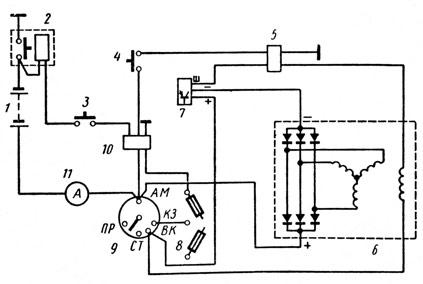
Fig. 135. 1 - rechargeable batteries; 2 - remote battery switch; 3 - buttons of the remote switch; 4 - thermostart device switch, 5 - generator excitation winding off relay; 6 - generator; 7 - voltage regulator; 8 - a safety lock, 9 - the switch of devices and a starter; 10 - contactor; 11 - ammeter
Battery Switch
On the car used switch battery type VK 860. It serves to disconnect batteries from the vehicle’s electrical system during long periods of parking and to protect batteries from short circuits.
The switch is mounted on the front battery mounting bracket. Rechargeable batteries they are turned on and off remotely from the driver’s cabin by a push-button switch by briefly pressing the button. In emergency situations, it is possible to manually disconnect the electromagnet of the remote switch manually - by pressing the switch stem through the rubber cap.
In the scheme of electrical equipment, it is possible to block the switching off of the batteries with the generator running to prevent overvoltages in the system. For this, the windings of the switch 2 (Fig. 135) are turned on by the opening contacts of the contactor 10, as a result of which the switching off rechargeable batteries it is possible only after disconnecting the generator from the electrical system by installing the key for the instrument switch and the starter in the neutral position.
can be installed any generatorbased on the needs of the product .. The electrical circuit of the generator G 273V is shown in figure 53.Figure 53. Generator installation D 273B: a) - electric circuit; b) - cut; c) - switching the voltage “summer” - “winter”; 1 - pulley; 2 - fan; 3 - a cover from the drive; 4 - stator; 5 - the rotor; 6 - rotor shaft; 7 - rectifier unit; 8 - cover from the side of slip rings; 9 - contact ring; 10 - bearing cap; 11 - make-up resistor; 12 - voltage regulator; 13 - brush holder; 14 - the switch of seasonal adjustment.
The generator has the following conclusions:
- “+” - connects the battery and load;
- B- for connection with the VC terminal of the instrument and starter switch;
- "-" connect to the mass of the power set;
- plug on the housing for phase output.
On the voltage regulator built into the generator brush holder, a seasonal adjustment switch is installed.
The level of the regulated voltage of the generator in the position of the switch L (summer) at a load current of 20 A, engine speed (1450 + 100) min-1, ambient temperature (25 + 10) ° C and the battery must be on 27 ... 28 V, in the 3 (winter) position - 28.8 ... 30.2 V.
On enginethe generator 6582.3701, TU 37.003.1365-88 can be installed.
Figure 53-1. Generator set 3122.3771: a) - electric circuit; b) cut; 1 - pulley; 2 - fan; 3, 8 - covers; 4 - stator; 5 - the rotor; 6 - rotor shaft; 7 - rectifier unit; 9 - contact ring; 10 - bearing cap; 11 - make-up resistor; 12 - voltage regulator; 13 - brush holder; C - capacitor 2,2 microfarad.
Attention!
- Do not connect and disconnect the plug connectors and the positive output of the generator set when the engine is running and the batteries are turned on, and the engine must not be started when the positive lead of the generator is disconnected.
- It is not necessary to check the serviceability of the generator set, closing the conclusions "+", "B" and "-" with jumpers to ground and between themselves.
- Do not connect the “Sh” terminal of the brush holder, access to which is open through the window in the brush holder casing, with the “+” and “B” terminals of the generator. This leads to failure of the regulator.
- It is impossible to check the condition of the electrical equipment and the individual wires with a megohm meter or a lamp to which the voltage is higher than 26 V, with the generator disconnected.
- You should not check the rectifier unit from a DC source with a voltage of more than 24 V, from an AC source, and also without a signal device connected in series with the rectifier unit.
- To avoid failure of the voltage regulator when recharging batteries from an external source, you must disconnect the batteries from the mains.
- When washing engineit is recommended to protect the generator from water ingress.
Generatorserves as a source of electricity on the car when the engine is running. The main parts of the generator are the stator and the rotor.
On the inner side of the stator teeth, there are 18 coils made of insulated copper wire and connected in series in six pieces in three groups. The groups are connected according to the “star” scheme, three terminals from which go to the rectifier unit.
When turning on the mass of the batteries and the instrument switch and starter in position "1" or "2", the current from the battery passes through the brushes and slip rings into the field winding. Around the screws of the excitation winding a magnetic flux is generated, guided by the rotor magnetic cores. When the rotor rotates, the magnetic flux rotates along with it, which intersects the windings of the stator coils. They produce alternating current (if the circuit is closed), going to the rectifier unit. In this block, it is converted to direct current, which goes to all consumers.
The generator holder G 273V has a built-in small-sized voltage regulator Ya120M, which is an integrated circuit. It serves to maintain the voltage generated by the generator within the prescribed limits.
The regulator has four outputs. With these pins, the regulator is installed in the brush holder so that the pins marked with the letters W, D, B, and P lie on the conductive busbars. Conductive terminal " AT»Voltage regulator is brought out and a wire is connected to it, which supplies the generator voltage regulation circuit.
The brush holder also has a make-up resistance, which serves to ensure reliable excitation of the generator at the engine idling speed.
On the case of the brush holder is placed the screw 10 of the regulator of the seasonal voltage regulation. The screw has two positions: “L” - summer, “3” - winter. When the screw is set to position “3”, the voltage maintained by the regulator is 1.5 ... 3.0 V higher than with summer regulation, which is necessary to improve the charging of batteries with increasing their internal resistance in winter conditions.
The alternator G 288 with electromagnetic excitation is also a three-phase twenty-pole electric machine with a built-in rectifier.
The generator has the following conclusions: “+” for connecting batteries and a load, “-” for connecting to the vehicle mass, “Ш” for connecting with the output “VK” of the instrument switch and starter and the output “Ш” of the voltage regulator.
The voltage regulator built into the generator's brush holder is assembled according to an integrated circuit and serves to automatically maintain the generator voltage within the prescribed limits necessary to ensure the charging mode of the battery and the work of consumers.
A voltage adjustment switch is fitted on the voltage regulator (see fig. 2). The level of the regulated voltage of the generator in the position of the switch L (summer) must be within 27 ... 28 V, in position 3 (winter) - 28.8 ... 30.2 V.
The generator is located in the upper front part of the engine and is attached by two paws to the bracket, and the third is attached to the tensioning bar, driven by two V-belts. The tension of the belts is carried out by moving the generator. Gear ratio generator 2.41.
The generator has the following conclusions:
"+ "- to connect the battery and load;
"- "- to connect to the mass of the car;
B - for connection with the VC terminal of the instrument switch and starter;
The plug on the housing for phase output.
Batteries
Lead-acid batteries with a voltage of 12 V and a capacity of 190 A-h. Two batteries are connected in series and provide a voltage of 24 V. Each battery consists of six batteries connected by inter-element connections with copper inserts to reduce internal resistance.
Brand of rechargeable batteries dd * KamAZ vehicles - 6ST-190T (6ST-190A). Such batteries make several factories. The trademark of the manufacturer is applied on the inter-element connection between the third and fourth batteries.