Synchronous generator - machine (mechanism) AC, which converts a certain type of energy into electricity. Such devices include electrostatic machines, galvanic cells, solar panels, thermopiles, etc. The use of each type of listed devices is determined by their technical characteristics.
Scope of application
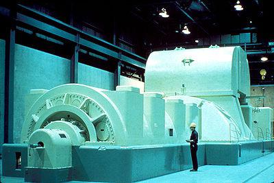
Synchronous units are used as sources of alternating current electricity: they are used at powerful thermal, hydro and nuclear power plants, at mobile power stations, transport systems (cars, airplanes, diesel locomotives). A synchronous unit is capable of operating autonomously - as a generator that powers any load connected to it, or in parallel with the network - other generators are connected to it.
A synchronous unit can turn on devices in places where there is no central power supply to electrical networks. These devices can be used on farms that are located far from populated areas.
Description of the device
The design of a synchronous generator is due to the presence of such elements as:
- A rotor, or inductor (moving, rotating), into which the excitation winding enters.
- An armature, or stator (immovable), into which the winding is connected.
- Unit winding.
- Stator coil switch.
- Rectifier.
- Several cables.
- Electrical compounding structure.
- Welding machine.
- Rotor coil.
- Regulated constant power supply.
Synchronous generator works as generators and motors. It can move from the generator operation schedule to the engine schedule - this depends on the action of the rotating or braking force of the device. In the generator diagram, mechanical energy enters and electrical energy comes out. In engine graphics, electrical energy enters and mechanical energy comes out.
The device is connected to the AC circuit different types nonlinear resistances. Synchronous units are alternators in power plants, and synchronous motors are used when a motor is needed that operates at a constant rotating frequency.
Operating principle of the unit
The operation of a synchronous generator is carried out on the principle of electromagnetic induction. During idle movement, the armature (stator) coil is open, so the magnetic field of the unit is formed by one rotor winding. When the rotor rotates from a wire motor, it has constant frequency, the rotor magnetic field moves through the conductors of the stator phase windings and induces repeating alternating currents - electrical driving force(EMF). EMF is sinusoidal, non-sinusoidal or pulsating in nature.
The excitation winding is intended to create an initial magnetic field to induce an electric driving force into the armature coil. If the armature of a synchronous generator is driven by rotation at a certain speed, then excited by a source of direct currents, then the excitation flow passes through the conductors of the stator coils, and alternating EMFs are induced in the phases of the coil.
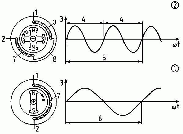
Three-phase device
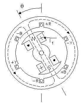
Three-phase synchronous generator- a device having a three-phase alternating current structure, which has a huge practical distribution. A rotating electromagnet is capable of generating a magnetic flux (alternating), which moves through the three phases of the existing stator winding. And the result of this is that an alternating EMF of the same frequency occurs in the phases, the phase shift occurs at an angle equal to one third of the period of rotation of the magnetic fields.
A three-phase synchronous generator is equipped so that the armature on its shaft is an electromagnet and is powered by the generator. When the shaft rotates, for example from a turbine, the generator supplies electric current, while the rotor winding is fed by the supplied current. From this, the armature becomes an electric magnet and, rotating with the same shaft, delivers a rotating electromagnetic field.
Synchronous three-phase hydro and turbo generators produce most of the electricity. Synchronous units are also used as electric motors in devices with a power exceeding 50 kW. During operation of a synchronous unit in the motor schedule, the rotor itself is connected to the source direct currents, the stator is connected to a three-phase cable.
Excitation structures
Any turbo, hydro, diesel generators, synchronous compensators, motors produced at at the moment, are equipped with the latest semiconductor structures, such as driving synchronous generators. These structures use the method of rectifying three-phase alternating currents of high or industrial frequency exciters or the voltage of the excited unit.
The design of the generator is such that the excitation structures can provide such unit operating parameters as:
- The first stage of excitement, that is, the initial stage.
- Idle work.
- Connecting to the network using precise synchronization or self-synchronization.
- Work in the energy structure with existing loads or overloads.
- The excitation of synchronous devices can be forced according to criteria such as voltage and current having a given multiplicity.
- Electric braking of the device.
Generator design
At the moment, many types of induction devices are produced, but the generator device is designed in such a way that they contain the same parts:
- An electromagnet or permanent magnet that produces a magnetic field.
- Winding with induced variable EMF.
To obtain the highest magnetic flux, all generators use a special magnetic structure, which consists of two steel cores.
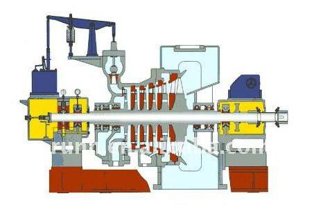
The windings that create a magnetic field are installed in the slots of one of the cores, and the windings induced by the EMF are installed in the slots of the other. One of the cores - the inner one - interacts with its winding and rotates around a horizontal or vertical rod. Such a rod is called a rotor. The immovable core with winding is called an armature (stator).
Device characteristics
To evaluate the function of synchronous generators, the same characteristics are used as those used in generators DC. Only some conditions differ and are supplemented.
The main characteristics of a synchronous generator are:
- Idling is the dependence of the EMF of the device on the excitation currents, and at the same time is an indicator of the magnetization of the magnetic circuits of the machine.
- An external characteristic is the dependence of the device voltage on the load currents. The voltage of the unit changes differently depending on the increase in load for its various types. The reasons that cause such changes are the following:
- Voltage drop across the inductive and active resistance of the device windings. It increases as the load of the device, that is, its current, increases.
- Change in the emf of the unit. Occurs depending on the reaction of the stator. With active loads, a decrease in voltage will be caused by a voltage drop in all windings, because the stator reaction entails an increase in the emf of the generator. For active-capacitive types of load, the magnetization effect causes an increase in the current voltage value compared to the nominal value.
- The control characteristics of a synchronous generator are the dependence of the excitation currents on the load currents. During the operation of synchronous units, it is necessary to maintain a constant voltage at their terminals, regardless of the nature and magnitude of the loads. This is easy to achieve if you regulate the EMF of the generator. This can be done by changing the excitation currents automatically depending on changes in loads, that is, with an active-capacitive load, you need to reduce the excitation current to maintain DC voltage, and with active-inductive and active - increase.
The power of a synchronous generator is determined by the following values:
- Appropriate voltage in the electrical network.
- Its EMF.
- Angle of measurement.
AC appliance
A synchronous alternating current generator is an electric machine that converts mechanical rotational energy into electrical energy of alternating currents. Powerful generators of such currents are installed:
- hydrogenerator turbogenerator - at power plants;
- AC devices of relatively low power - in autonomous power supply systems (gas turbine power plant, diesel power plant) and in frequency converters(motor-generator).
Currently, many types of such devices are produced, but they all have a common structure of the main elements:
- armature (stator) - stationary;
- rotor rotating around an axis.
In large industrial generators, an electromagnet, which is a rotor, rotates. At the same time, the windings with induced EMF, placed in the stator slots, remain stationary.
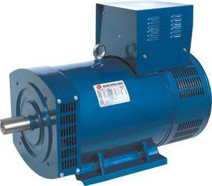
In devices such as a low-power synchronous generator, the magnetic field is created by a rotating permanent magnet.
Types of synchronous units
There are the following types of synchronous generators:
- Hydro - in it the rotor has a difference due to the presence of pronounced poles, is used in the production of electricity, and operates at low speeds.
- Turbo - differs in the non-salient pole structure of the generator, produced from turbines different types, the rotation speed is quite high, reaching about 6000 rpm.
- Synchronous compensator - this unit supplies reactive power, is used to improve the quality of electricity to stabilize the voltage.
- Double power asynchronous unit - the device of this type of generator is that it connects both rotor and stator windings from the supplier of currents with different frequencies. An asynchronous work schedule is created. It is also distinguished by the stability of its work schedule and the fact that it transforms different currents phases and is used to solve highly specialized problems.
- Bipolar impact unit - works in a short circuit schedule, acts briefly, in milliseconds. Also tests high voltage devices.
Types of units
The synchronous generator (motor) is divided into several models, which are designed for various purposes:
- Stepping (pulse) - used for drives of mechanisms with a start-stop operating cycle or continuous motion devices with a pulse control signal (counters, tape drives, CNC machine drives, etc.).
- Gearless - for use in autonomous systems.
- Non-contact - used to operate as power plants on ships of the sea and river fleet.
- Hysteresis - used for time counters, in inertial electric drives, in automatic control systems;
- Induction motors - for supplying electrical installations.
Separation by rotor type
According to the type of rotor device, the generator device is divided into:
- Salient pole - with protruding or pronounced poles. These rotors are used in quiet-running generators whose rotation speed does not exceed 1000 rpm.
- A non-salient pole is a cylinder shaped rotor that has no salient poles. These armatures come in two-pole and four-pole types.
In the first case, the rotor consists of a crosspiece on which the pole cores or field windings are fixed. Secondly, high-speed units with a speed of 1500 or 3000. The rotor is made in the form of a cylinder of fairly high quality steel with grooves; an excitation winding is installed in them, consisting of individual windings of different widths.
Electric generator– one of the constituent elements of an autonomous power plant, as well as many others. In fact, it is the most important element, without which the generation of electrical energy is impossible. An electric generator converts rotational mechanical energy into electrical energy. The principle of its operation is based on the so-called phenomenon of self-induction, when an electromotive force (EMF) arises in a conductor (coil) moving in the magnetic field lines, which can (for a better understanding of the issue) be called electric voltage (although this is not the same thing ).
The components of an electric generator are a magnetic system (mainly electromagnets are used) and a system of conductors (coils). The first creates a magnetic field, and the second, rotating in it, converts it into an electric one. Additionally, the generator also has a voltage removal system (commutator and brushes, connecting the coils in a certain way). It actually connects the generator with consumers electric current.
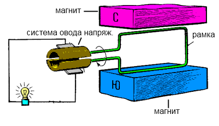
You can get electricity yourself by carrying out the simplest experiment. To do this, you need to take two magnets of different polarities or turn two magnets with different poles towards each other, and place a metal conductor in the form of a frame between them. Connect a small (low-power) light bulb to its ends. If you start to rotate the frame in one direction or another, the light bulb will begin to glow, that is, an electric voltage appears at the ends of the frame, and an electric current flows through its spiral. The same thing happens in an electric generator, the only difference is that in an electric generator there is more complex system electromagnets and a much more complex coil of conductors, usually copper.
Electric generators differ both in the type of drive and in the type of output voltage. By type of drive that sets it in motion:
- Turbogenerator – driven by a steam turbine or gas turbine engine. Mainly used in large (industrial) power plants.
- Hydrogenerator – driven by a hydraulic turbine. It is also used in large power plants operating through the movement of river and sea water.
- Wind generator – driven by wind energy. It is used both in small (private) wind power plants and in large industrial ones.
- The diesel generator and gasoline generator are driven by a diesel and gasoline engine, respectively.
By type of output electric current:
- DC generators - the output is direct current.
- Alternating current generators. There are single-phase and three-phase, with single-phase and three-phase AC output respectively.
Different types of generators have their own design features and practically incompatible nodes. What unites them only general principle creating an electromagnetic field by mutual rotation of one system of coils relative to another or relative to permanent magnets. Due to these features, only qualified specialists can repair generators or their individual components.
Story
Systems producing alternating current were known in simple types since the discovery of magnetic induction of electric current. Early machines were developed by pioneers such as Michael Faraday and Hippolyte Pixie.
Faraday developed a "rotating triangle" whose action was multipolar- each active conductor was passed sequentially through an area where the magnetic field was in opposite directions. The first public demonstration of the most powerful "alternator system" took place in 1886. A large two-phase alternating current generator was built by British electrician James Edward Henry Gordon in 1882. Lord Kelvin and Sebastian Ferranti also developed an early alternator that produced frequencies between 100 and 300 hertz. In 1891, Nikola Tesla patented a practical "high frequency" alternator (which operated at a frequency of about 15,000 hertz). After 1891, multiphase alternators were introduced.
The principle of operation of the generator is based on the action of electromagnetic induction - the occurrence of electrical voltage in the stator winding located in an alternating magnetic field. It is created with the help of a rotating electromagnet - rotor when direct current passes through its winding. AC voltage converted to DC by a semiconductor rectifier.
Car generator
Car alternator. Drive belt removed.
The alternator is used on modern cars for charging batteries and for powering automobiles electrical system. Alternating current generators do not use a commutator, this gives big advantage over DC generators: they are simpler, lighter and cheaper. Automotive alternators use a set of rectifiers (diode bridge) to convert alternating current to direct current. To produce low ripple DC current, car generators alternating current have a three-phase winding and a three-phase rectifier.
Modern automobile alternators have a voltage regulator built into them. Previously, only analog voltage regulators were installed. At the moment, relay regulators have switched to a digital channel, the so-called CAN bus.
Marine alternators
Marine alternating current generators in yachts with appropriate adaptation to salt-water environments.
Brushless Alternators
A brushless generator consists of two generators on one shaft. Small brushless generators may look like one unit, but the two parts are easily identifiable on the large generators. Most of the two is the main generator and the smaller one is the exciter. The exciter has stationary field coils and a rotating armature (power coils). The main generator uses opposing rotating field configurations and stationary coils. The bridge rectifier (rotating rectifier) is mounted on a plate attached to the rotor. No brushes or slip rings are used, reducing the number of wearing parts.
Induction generator
Unlike other generators, the operation of an induction generator is based not on a rotating magnetic field, but on a pulsating one, in other words, the field changes not as a function of displacement, but as a function of time, which ultimately (induction of EMF) gives the same result.
The design of induction generators involves the placement of both a constant field and coils for inducing EMF on the stator, while the rotor remains free from windings, but must have a tooth shape, since the entire operation of the generator is based on the tooth harmonics of the rotor.
Generators for small energy
For powers up to 100 kW, single- and three-phase generators with excitation from permanent magnets are widely used. The use of high-energy permanent magnets of the neodymium-iron-boron composition made it possible to simplify the design and significantly reduce the size and weight of generators, which is critical for small-scale wind energy.
Alternator Design
In the most general case, the most commonly used three phase generator alternating current consists of a salient-pole rotor with one pair of poles (low-power high-speed generators) or 2 pairs of them, arranged crosswise (the most common generators with powers up to several hundred kilowatts. This design not only allows for a more rational use of the material, but also for the industrial frequency of alternating current 50 Hz gives an operating rotor speed of 1500 rpm, which is in good agreement with the traction speed of diesel engines of this power), as well as a stator with 3 (in the first case) or 6 (in the second) power windings and poles. The voltage from the power windings is that which is supplied to the consumer.
The rotor can be made with permanent magnets only for very low-power generators; in all other cases it has a so-called winding. excitation winding, that is, it is a direct current electromagnet, powered in a rotating rotor through a brush-commutator assembly with simple ring contacts that are more resistant to wear than the split lamella commutator of DC machines.
In any powerful alternating current generator with an excitation winding on the rotor, the question inevitably arises - what magnitude of excitation current should be supplied to the coil? After all, the output voltage of such a generator depends on this. And this voltage must be maintained within certain limits, for example, 380 Volts, regardless of the current in the consumer circuit, a significant value of which can also significantly reduce the output voltage of the generator. In addition, the load across phases can generally be very uneven.
This issue is resolved in modern generators, as a rule, by introducing electromagnetic current transformers into the output circuits of the generator phases, connected by the secondary windings in a triangle or star, and producing at the output an alternating three-phase voltage with an amplitude of unity - tens of volts, strictly proportional and phase-matched with the magnitude of the load current of the generator phases - the more consumed in At a given moment there is current in a given phase, the greater the voltage at the output of the corresponding phase of the corresponding current transformer. This achieves a stabilizing and auto-regulating effect. All three regulating phases from the secondary windings of the current transformers are then connected to a conventional 3-phase rectifier made of 6 semiconductor diodes, and its output produces a direct current of the required value, which is supplied to the rotor excitation winding through a brush-collector assembly. The circuit can be supplemented with a rheostat unit for some freedom in regulating the excitation current.
In outdated or low-power generators, instead of current transformers, a system of powerful rheostats was used, with the isolation of the operating excitation current by changing the voltage drop across the resistor when the current through it changes. These schemes were less accurate and much less economical.
In both cases, there is the problem of the appearance of an initial voltage on the power windings of the generator at the moment it begins to operate - indeed, if there is no excitation yet, then the current in the secondary windings of the current transformers has nowhere to come from. The problem, however, is solved by the fact that the iron of the rotor yoke has some capacity for residual magnetization; this residual magnetization is sufficient to excite a voltage of several volts in the power windings, sufficient to self-excite the generator and reach its operating characteristics.
In self-excited generators, accidental supply poses a serious danger external voltage industrial electrical network to the stator power windings. Although this does not lead to any negative consequences for the generator windings themselves, a powerful alternating magnetic field from the external network effectively demagnetizes the stator, as a result of which the generator loses the ability to self-excite. In this case, an initial supply of excitation voltage from some external source is required, for example, car battery, sometimes such a procedure completely cures the stator, but in some cases the need to supply external excitation remains forever.
Main alternator
The main generator consists of a rotating magnetic field, as stated earlier, and a stationary armature (generator windings)
Hybrid cars
See also
Links
- Alternators. Integrated Publishing (TPub.com).
- Wooden Low-RPM Alternator. ForceField, Fort Collins, Colorado, USA.
To convert various types of energy into electrical energy, special devices are used. One of the simplest mechanisms is a direct current generator, which can be bought at any electrical goods store or assembled with your own hands.
A DC generator is a device that converts mechanical energy into electrical energy for further use in an external circuit. In this case, any mechanical force can serve as a source of mechanical energy: rotating a special handle, connecting a motor to a device. It should be noted that the overwhelming majority of apartments and houses within any city are supplied with the help of just such generators, only of the industrial type.
Photo – DC generator
An electric current generator can act completely opposite. Reverse conversion electrical energy The mechanical one is carried out by means of an electric motor. Many motors are equipped with a manual (mechanical) drive, which when correct connection can transform energy and networks in the opposite direction.
Operating principle and device
A DC generator consists of two main parts - the stator and the rotor. Other details:
- Housing: outer frame of the generator. Often made of cast iron or steel. The housing provides mechanical strength for the entire generator (or electric motor) structure. It also transmits the magnetic flux generated by the poles;
- Magnetic poles. They are connected to the housing using screws or bolts, and the winding is placed on them;
- The stator, core or yoke is made of ferromagnetic alloys; an excitation coil is installed on this part. The cores are equipped with poles that help determine the direction of flow of charged particles. It is the magnetic tips that generate the magnetic field necessary for the operation of the device;
- Rotor: generator armature. The core is assembled from individual steel plates, this helps to increase the efficiency of the generator and reduce the formation of eddy currents. When installing the plates, depressions are formed into which the armature winding or self-excitation winding is wound;
- Commutator and brushes. The brushes are made of graphite, and there are at least two of them in the generator. You can find out the number of brushes by counting the poles - this indicator is identical.
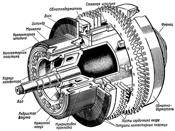
Photo - permanent generator armature design
To connect the circuit terminals, collector plates are used; they are made of copper, which is known as an excellent conductor of electrical signals.
The operating principle of a DC generator is based on the formula:
According to it, when a conductor moves in a magnetic field (which allows reducing magnetic power lines), induced emf is dynamically produced in the conductor. The magnitude of the generated EMF can be specified using the DC generator equation.
One of the main functions of a device for converting alternating current is to generate emf into direct current. The direction of the generated EMF will change through each conductor through which energy passes as the rotor rotates. With the help of a commutator, a constant flow of charged particles is formed at the output of the generator. The output signal then looks like this:
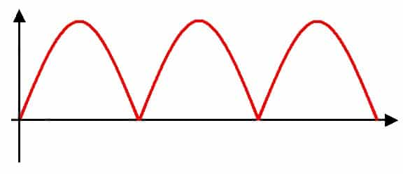
Photo – DC generator output signal
Types
There are such types of DC generators: self-excited and operating on the principle of independent switching (diagram below). Excitation methods depend on the power supply type of the device. A self-exciting electric generator operates from external sources, this can be battery or a wind generator. Also external system excitation is often implemented using magnets (mainly on devices with low power, up to several tens of watts).
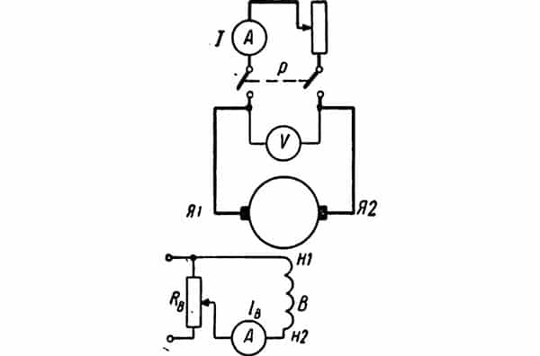
Photo - circuit of a generator with independent switching
The independent generator is excited by power from the device winding. These devices are also divided into types:
- Shunt or parallel excitation;
- Consistent.
The first ones are different parallel connection armature windings with excitation winding, the second, respectively, serial connection these details.
Anchor reaction
This is a fairly common occurrence when the generator is idling. It is characterized by the superposition of resulting magnetic fields between the stator and rotor, which reduces the voltage and reduces the magnetic field. As a result, it falls electromotive force devices, interruptions in operation are observed, the synchronous generator may even overheat or catch fire due to sparks that appear from improper friction of the brushes.
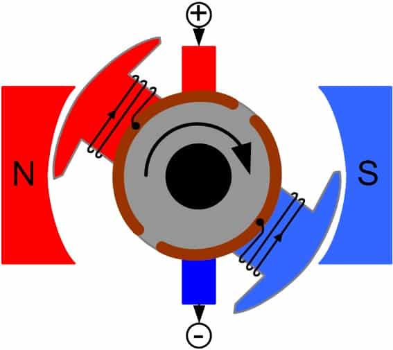
Photo - generator poles
If this problem occurs, you can do the following:
- Compensate the magnetic field using additional poles. This will help cope with the drop in this characteristic at individual points in the circuit;
- Repairs are often carried out by simply moving the commutator brushes.
Purpose
Unlike alternating current generators, devices with a constant type of electricity require an uninterruptible power supply that constantly directs DC current to the armature winding. Because of this, the scope of application of such devices is quite highly specialized; at the moment they are rarely used anywhere.
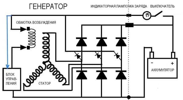
Photo - principle of operation of the generator
They are often used to power electric vehicles in cities. DC generators are also used to operate an electric car, motorcycle, or as ship exciters or welding inverters. They are used as low-speed motors for wind turbines.
A diesel DC generator can be used as an electric motor for powerful industrial machines (traction tractor, combine harvester, etc.) and a tachogenerator. At the same time, to control the tractor, a powerful unit is required, which technical specifications not inferior to 300 - 400 kW. At the same time, diesel can also replace gas.
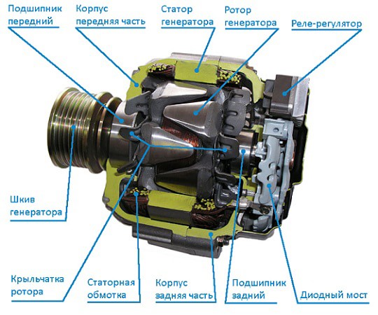
Photo - car generator device
The DC generator has the following characteristics (calculation is made at n=const):
- Idling E=f(iв)
- Formula for series excitation U=f(I)
- Parallel excitation U=f(I)
The study shows that characteristics can be calculated based on n=0.
You can find standard indicators in the device passport, and they often deviate by several percent (the possible error is also indicated in the instructions for the generator). Homemade generators may have different characteristics from those presented; you can select the necessary data using reference books. You can check them by measuring the existing parameters, there is different ways, depending on the type of generator.
Advantages of a DC generator:
- Unlike a variable-type device, it does not lose energy due to hysteresis, as well as due to eddy currents;
- Can work in extreme conditions;
- Has a relatively light weight and small design;
This device also has disadvantages. The main thing is the need for an external power source. But sometimes this feature is used as a regulator of an electric machine.
You can buy DC generators in online stores, on import sites, as well as in factories and markets. Sales are also made second-hand, but we do not recommend using used ones electrical appliances. The cost depends on the purpose and power of the device. The price for 4GPEM varies between 30,000 rubles, and PM-45 - 60,000. Upon purchase, a presentation of the work must be made.
In practice, several types of generators are used. But each of them includes the same constituent elements. These include a magnet, which creates a corresponding field, and a special wire winding, where an electromotive force (EMF) is created. IN the simplest model In the generator, the role of the winding is performed by a frame capable of rotating around a horizontal or vertical axis. The amplitude of the EMF is proportional to the number of turns present on the winding and the amplitude of the magnetic flux oscillations.
To obtain a significant magnetic flux, generators use a special system. It consists of a pair of steel cores. The windings that create an alternating magnetic field are placed in the grooves of the first of them. Those turns that induce EMF are placed in the grooves of the second core.
The inner core is called the rotor. It rotates around an axis together with the winding on it. The core that remains motionless performs the function of a stator. In order to make the magnetic induction flux as strong as possible and energy losses to be minimal, they try to make the distance between the stator and the rotor as small as possible.
On what principle does the generator work?
An electromotive force arises in the stator windings immediately after the appearance of an electric field, which is characterized by vortex formations. These processes are generated by a change in magnetic flux, which is observed during accelerated rotation of the rotor.
The current from the rotor is supplied to the electrical circuit using contacts in the form of sliding elements. To make this easier, rings called contact rings are attached to the ends of the winding. Fixed brushes are pressed against the rings, through which the connection between electrical circuit and the winding of the moving rotor.
In the turns of the magnet winding, where the magnetic field is created, the current has a relatively small strength when compared with the current that the generator gives to the external circuit. For this reason, the designers of the first generators decided to divert current from windings located statically, and supply a weak current to a rotating magnet through contacts that provide sliding. In generators low power the field creates a permanent magnet that can rotate. This design allows you to simplify the entire system and avoid the use of rings and brushes at all.
A modern industrial electric current generator is a massive and bulky structure, which consists of metal structures, insulators and copper conductors. The dimensions of the device can be several meters. But even for such a solid structure, it is very important to maintain the exact dimensions of the parts and the gaps between the moving parts of the electrical machine.