Operating principle (by the example of a parallel excitation engine). If a voltage U is connected to the motor, then a current I in flows through the excitation circuit, and a current I I flows through the armature circuit. The excitation current creates an MDS F in = I in W in, which excites in the machine a magnetic flux F in. The armature current, in turn, creates the magnetic flux of the armature reaction Φ i. The resulting magnetic flux f cut = f in + f i.
The concept of the motor is to activate the stator field and allow the rotor poles to move to the desired position, which provides magnetic alignment. Instead of providing rotating magnetic field or field-switched field switching are more fixed. The first sequence of switches, shown in 13, will result in a clockwise rotation; the second sequence rotates counterclockwise. Sick. Figure 13 A diagram illustrating how a switching sequence generates motion steps in a stepper motor.

Fig.1.23 Fig. 1.24
In the armature circuit, the current I I creates a voltage drop R I and I. In accordance with the law of electromagnetic force EMC, the interaction of current I and magnetic flux Φ res creates a torque of M bp. In the steady state mode M vr. = M ave. When the armature conductors intersect the magnetic field Φ res, they are in accordance with the law electromagnetic induction EMR induced EMF, which is directed against the voltage of the network U.
The simple concept of a stepper motor is explained using a permanent magnet on a rotor with two sets of poles on a stator. In fact, the rotor consists of many magnetic poles aligned with the “teeth” on the rotor. These teeth are positioned so that only one set of teeth is in perfect alignment with the stator poles at any one time. If we take the number of times that the stator force is applied to move one tooth through a 360 ° rotation, we can calculate the pitch angle. For example, if a tooth moves 360 ° with 200 power levels, the angle pitch is calculated by dividing 360 ° by 200; This gives us an 8 ° movement per step.
Engine classification. According to the wiring diagram of the excitation windings of the main poles of the engines direct current They are divided into engines of independent, parallel, sequential and mixed excitation.
In engines of independent excitation, the field winding is powered from a separate source. constant voltage. In motors of parallel excitation, the field winding and the armature winding are connected in parallel and are powered from the same source. In the engines of sequential and mixed excitation there is an excitation winding connected in series with the armature winding. In low-power engines, a flux of excitation can be created with the help of permanent magnets. The most widely used are engines of parallel and mixed excitation.
The pitch of the angle will determine how accurate the stages of movement are for the engine. Other types of stepper motors use a high permeability rotor instead of a permanent magnet rotor. The magnetic fields of the rotor will even out and keep magnetism during operation. These stepping motors are called variable resistance stepping motors.
Most stepper motors use instructions or commands that are produced by computer processors. Sick. 14 Stepper motor and corresponding controller board. Pay attention to the small size of the engine. A shunt dc motor uses a shunt field as the main magnetic field in the stator. A shunt field consists of several turns of a small wire and is connected or shunted across the reinforcement. The shunt field can have a series resistor to control the amount of current in the field.
Basic equations and quantities characterizing engines. These values are: mechanical power on the shaft P 2, the supply voltage U, the current consumed from the network I, the armature current I I, the excitation current I in, the rotation speed n, the electromagnetic moment M em. The relationship between these quantities is described:
Ø Electromagnetic moment equation:
The principle of direct current is based on the concept of switching. This switch and brush connection always maintain a constant current direction and a magnetic field direction. The speed and current on the rotor are inversely proportional. If the rotor rotates faster, the amount of oncoming emf increases. and less voltage difference and, therefore, less current. There are many variations of the shunt motor used for specialized purposes.
Choose the correct answer for each of the following statements. A. Voltage, Frequency, Current, and Speed. B. voltage, current, speed and torque. C. voltage, current and power. D. Voltage, current, speed and power. The effect of the generator in the engine gives.
M em = S m I I F;
Ø equation of the electric state of the armature circuit:
U = E pr + R i I i; (1.4)
E pr = C E nF;
Ø equation of moments:
M em = M with + M pot + M d,
where M with - the moment of resistance on the shaft, created by the load; M pot - the moment of loss created by all types of losses in the engine; M d - the dynamic moment created by inertial forces;
C. counter electromotive force. A DC motor consumes more current with a mechanical load applied to its shaft because. B. voltage differential decreases. D. torque depends on the magnetic force. The direction of rotation of the composite interpolar motor can be reversed to the direction of the current flow through.
C. Armature, Interpol and Rows. The speed of the DC motor can be reduced below the rated speed without loss of torque by reducing the voltage by. A. simplicity in construction. B. Speed control is higher and lower than base speed.
Characteristics of engines. The most important of the characteristics is the mechanical n (M s) - the dependence of the rotational speed n on the shaft torque (hereinafter the “c” index is lowered) at U = const, I in = const. It shows the effect of mechanical load (torque) on the motor shaft on the rotational speed, which is especially important to know when choosing and operating engines. Other engine characteristics: adjusting n (I c), speed n (I i), workers M, P 1, n, I, h (P 2) are not discussed in detail here.
C. Excellent torque and speed control. Complete the following statements. As the DC motor reaches its rated speed, the current of its armature is. These engines have two pins. Applying voltage to the terminals results in a proportional speed of the output shaft in a steady state.
The stator includes a housing, permanent magnets and brushes. The rotor consists of an output shaft, windings and a switch. Please note that in this picture there is a gearbox and an encoder connected to the engine. The forces inside the engine that cause the rotor to rotate are called Lorentz forces. If an electron moves through a magnetic field, it experiences force. If we have a current passing through a wire in a magnetic field, the wire experiences a force proportional to the transverse product of the current and the magnetic field.
Mechanical characteristics can be natural and artificial. Under natural characteristics are understood to be characteristics taken in the absence of any additional resistance in the circuit, for example, rheostats in armature or excitation circuits, artificial - in the presence of such resistances.
Mechanical equation engine performance. It can be obtained from (1.1). Substitute instead of E its value in (1.4), then
You can easily find the direction of this force using the Rule of the right hand. Now imagine that this single wire is replaced by a loop of wire. Between the “pole” magnets, it looks like two wires with current flowing in opposite directions. The forces on the wires make the loop rotate.
The coil consists of many such loops and is attached to the rotor and rotates. The magnitude and direction of the forces on the wires remain approximately constant. However, the resulting torque varies with the angle. When the coil starts, there is a maximum torque. As the coil moves, the torque lever decreases and the torque decreases. Finally, when the coil is vertical, there is no torque.
n = (U - R i I am) / C E F. (1.5)
Replacing I and its value from (1.2), we obtain the equation of mechanical characteristics:
n = ![]() (1.6)
(1.6)
The type of mechanical characteristics is determined by the nature of the dependence of the flow otnagruz engine, which in turn depends on the wiring circuit of the excitation winding.
To maintain almost constant torque on the rotor, we can do two things. First, we can change the current through the coil every half the queue. Therefore, instead of a variable torque, such as the first in the figure below, the torque is always in one direction. In addition, additional coils can be used. When these coils are displaced at different angles around the engine, the resulting torque becomes the sum of the color torque curves in the figure below.
The resulting torque is always greater than zero, but not constant. This angle-dependent variation is called torque ripple. The process of switching the direction of the current is called switching. The brushes are attached to the two external wires of the electric motor, and the switch segments slide along the slots so that the current through the coils switches at appropriate angles. Switching can also be done electronically. The following diagram shows how brushes and switches work. A valid switch must have at least three segments.
Engine reversing. Under the reversal of the engine understand the change in the direction of rotation of its anchor. Possible ways of reversing follow from relation (1.2). If you change the direction of the armature current or the flow of the machine, then the sign, and hence the direction of the torque, changes. In practice, this is achieved by switching the leads or the armature winding, or the excitation winding. However, the simultaneous switching of the leads of both windings or a change in the polarity of the voltage supplying the motor (other than the independent excitation motor) does not lead to a change in the sign of the torque and, therefore, to a change in the direction of rotation.
Let's start by writing the energy conservation equation in the engine. Power is entered as electric powerand the engine converts it to mechanical power. However, part of the power is lost as heat, due to the ohmic heating of the motor coils. We can rewrite it in terms of electrical and mechanical quantities as.
The defining equation of the engine. Reverse EMF is proportional to engine speed. This is how dams create hydropower. This equation allows us to construct the curve of the speed of rotation of the motor. The curve is just a straight line, as shown below. This is the maximum torque that the engine can generate. We can also calculate the stop current by dividing the torque into a permanent motor. This is the maximum motor current.
Engine start direct current. There are two basic requirements for engine start-up: to ensure the torque required for starting and accelerating the armature and not allowing an excessively high current that is dangerous for the engine to flow through the armature. Three methods of starting are practically possible: direct starting, starting when the rheostat is switched on in the armature circuit, and starting at low voltage in chain anchors.
With a direct start, the armature circuit is switched on immediately at full voltage. Since the anchor is immobile at the first moment of launch (n = 0), there is no back-EMF (Е pr = С Е nФ). Then from (1.4) it follows that the starting current of the armature I i, n = U / R i.
Since R i = 0.02 ¸ 1.10 Ohm, then I i, n = (50 ¸100) I nom, which is unacceptable. Therefore, direct start-up is possible only for low-power engines, where I, n (4-6) I n and engine acceleration lasts less than 1 s.
Start when the start-up rheostat R n is turned on sequentially with an anchor, consider the example of the circuit in Fig. 1.25. The starting current in this case is equal to:
I i, n = U / (R i + R n). (1.7)
The resistance R n = U / I i, n - R i is chosen so that at the initial moment of start, when Е av = 0, I i, n = (1.4¸2.5) I Mr. (the larger number refers to engines lower power).
As the armature accelerates, E pr increases, which decreases the voltage at the anchor (i.e., the numerator decreases (1.7)), and the resistance of the rheostat R p is output.
Before starting, the rheostat R p is derived, which is necessary to ensure the maximum flow and, therefore, the moment at start-up (M n = C m I i, n F). As the armature accelerates, the rheostat R p is inserted until the required rotational speed is reached.
Starting with limited starting current is possible when the motor armature is supplied from a separate source (generator, rectifier) with adjustable voltage. Restriction starting current and smooth engine acceleration is ensured by gradually increasing the armature voltage from zero to the required value.
The considered method is used in control systems and regulation of high-power DC motors (see section 1.4.3).
§ 115. CHARACTERISTICS OF DC MOTORS
The working properties of the engines are determined by their performance characteristics, which are dependencies of the number of revolutions t, torque Me, consumed current I, power P1 and efficiency η on useful power on shaft Р2. These dependences correspond to the natural conditions of the engine, t. E. The machine is not regulated and the mains voltage remains constant. So
as with a change in useful power P2 (i.e. the load on the shaft), the current in the armature also changes
machines, then performance is often built depending on the current in the armature. The dependences of the torque and speed of rotation on the current in the armature for a motor of parallel excitation are shown in fig. 152, and the diagram of one hundred is shown above (see Fig. 151).
The engine speed is determined by the following expression:
\u003e As the load on the motor shaft increases, so does the current in the armature. This causes an increase in the voltage drop of the resistance of the armature winding and brush contacts.
Since the excitation current remains unchanged (the machine is unregulated), the magnetic flux is also constant. However, as the current in the armature increases, the demagnetizing effect of the armature reaction flux increases and the magnetic flux F decreases slightly. An increase in Iyr causes a decrease in engine speed, and a decrease in F increases speed. Typically, the voltage drop affects the speed change to a slightly greater degree than the armature response, so with increasing current in the armature the speed decreases. The change in speed for an engine of this type is insignificant and does not exceed 5% when the load changes from zero to nominal, that is, the motors of parallel excitation have a hard speed characteristic.
With a constant magnetic flux, the dependence of the moment on the current at the anchor will be represented by a straight line. But under the influence
The torque of the armature response engine with an increase in load is a slight decrease in the magnetic flux and the dependence of the moment goes slightly below the straight line.
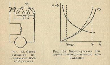
The scheme of a sequential excitation engine is shown in fig. 153. The starting resistor of this engine has only two clips, since the field winding and the armature form one series circuit. Engine characteristics are shown in Fig. 154. The number of revolutions of the engine of sequential excitation is determined by the following expression:
![]()
where rc is the resistance of the series excitation winding. In a sequential motor, the magnetic flux does not remain constant, but changes dramatically with load changes, which causes a significant change in speed. Since the case of voltage in the armature resistance and in the excitation winding is very small compared to the applied voltage, the speed can be approximately determined by the following expression:
If we neglect the saturation of steel, then we can assume that the magnetic flux is proportional to the current in the field winding, which is equal to the current in the armature. Consequently, in a sequential excitation engine, the rotational speed is inversely proportional to the current in the armature and the speed decreases sharply with increasing load, i.e. the engine has a soft speed response. With decreasing load, the engine speed increases. When idling (I = 0), the engine speed increases endlessly, i.e. the engine goes into spacing.
Thus, the characteristic property of the engines of sequential excitation is the inadmissibility of load shedding, i.e., idling or at low loads. The engine has a minimum allowable load of 25-30% of nominal. When the load is less than the minimum allowable speed of the engine increases sharply, which can cause its destruction. Therefore, when discharges or abrupt reductions in load are possible, the use of sequential excitation motors is unacceptable.
In engines of very low power, the load shedding does not cause separation, since the mechanical losses of the engine will be a sufficiently large load for it.
The torque of a sequential excitation engine, taking into account the proportional relationship between the magnetic flux and the current in the armature (F = C "I), can be defined by the following expression:
where K ’= KC’
those. torque is proportional to the square of the current. However, at high currents, the saturation of the steel affects and the moment dependence approaches a straight line. Thus, engines of this type develop large torques at low revs, which is essential when starting large inertial masses and overloads. These engines are widely used in transport and lifting devices.
With mixed arousal, both consonant and on-off excitation windings are possible.
Engines with counter-winding switching are not widely used, as they have poor starting properties and work unstable.
The speed characteristics of engines of mixed excitation occupy an intermediate position between the characteristics of engines of parallel and series excitation.
With increasing current in the armature, the armature speed decreases more than for motors of parallel excitation, due to an increase in the magnetic flux caused by an increase in current in the series excitation winding. When idling, the engine of mixed excitation is not peddling, since the magnetic flux does not decrease to zero due to the presence of a parallel excitation winding.
As the load increases in engines of mixed excitation, the magnetic flux increases and the torque increases more than in engines of parallel excitation, but to a lesser extent than in series excitation engines.