Check
To perform the work will require a multimeter.
1. Remove the generator from the car (see above, "Generator - removal and installation").
2. We clean the external surface of the generator from dirt with a rag.
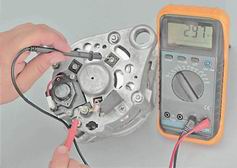
3. Connecting the positive probe of the ohmmeter to the output "30", and the negative probe to the generator body, check for the "breakdown" diodes of the generator.
If the ohmmeter shows resistance close to zero, a breakdown of one or several diodes has occurred or the stator winding is shorted to the case.
4. Connecting the positive probe of the ohmmeter to the output "30", and the negative - to one of the mounting bolts of the rectifier unit, check the positive diodes.
5. Connecting the positive ohmmeter probe to one of the mounting bolts of the rectifier unit, and the negative one to the generator body, check for negative breakdown of the generator diodes.
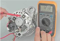
If the ohmmeter shows resistance close to zero, a breakdown of one or more diodes occurred.
6. To test the capacitor, remove it from the generator (see "Repair" below). When connecting the ohmmeter probes to the capacitor leads, the resistance should decrease and then gradually increase.
7. To check the regulator, remove it from the generator (see "Repair" below). When you click on the brush, they must move freely in the grooves, to be spring-loaded. The protrusion of the brushes in a free state from the brush holder must be at least 5 mm, otherwise we replace the regulator.
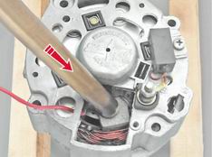
8. The output "B" of the voltage regulator is connected with the positive output of the battery, and the negative output (indicated by arrow A) - with the "mass". With a voltmeter we measure the voltage at the contacts of the brush assembly.
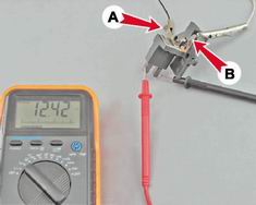
If the voltage is absent, the regulator is faulty.
9. Connecting one contact of the ohmmeter to the housing, and the other to the contact ring of the rotor, check for the absence of the short circuit of the rotor winding on the generator housing.
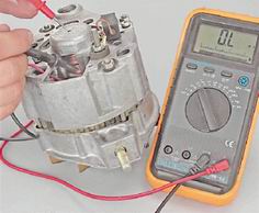
If the ohmmeter shows a resistance close to zero, a short circuit occurs.
A defective rotor, stator, capacitor, or voltage regulator must be replaced. If one diode fails, we replace the rectifier assembly.
To perform the work will require: two- or three-tongs puller, mandrel for pressing out the front bearing, mandrel for pressing in the rear bearing.
1. Holding the rotor with a screwdriver against rotation, with an Allen key on 19 mm turn off the nut securing the pulley and the impeller generator.

2. Remove the pulley parts from the shaft, the generator cooling impeller, the segment key and the restrictive washers.

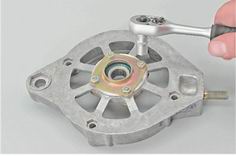
3. To remove the voltage regulator disconnect the wire from him.

4. Phillips screwdriver unscrew the two screws attaching the voltage regulator.
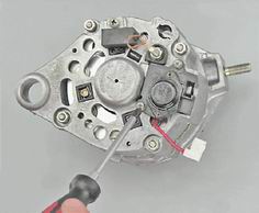
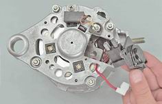
5. We take out the voltage regulator assembly with the brush assembly from the generator housing.
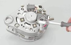
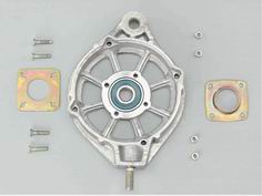
6. Socket wrench on 10 mm turn off the four nuts securing the generator covers and remove the connecting bolts.
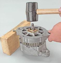
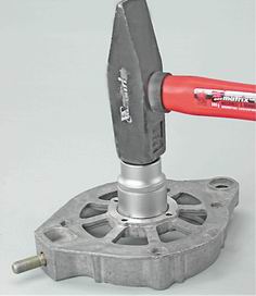
7. Having supported the front cover of the generator on a wooden bar, we lightly strike the shaft with the stator.
8. Remove the generator cover and the remote sleeve.

9. Check the technical condition of the front bearing. Holding the lid, we swing it and turn the inner ring of the bearing in both directions. The rotation of the bearing should be smooth, axial play slightly. Defective bearing replaceable.
10. When replacing the front bearing face or cap wrench by 8 mm turn off the four nuts. If the nuts do not turn away, then grind off the blackened ends of the bolts.
Attention!
After installing the bolts and tightening the nuts, the ends of the bolts must be unscrewed. If the length of the bolts is not enough for their disclosure, then replace the bolts with new ones.
11. Take out the bolts and remove the inner and outer washers of the bearing.
12. Using a suitable mandrel, press out the bearing.
13. Having supported the edges of the back cover of the generator (for example, two wooden bars), knock out the rotor with a soft metal hammer.
14. Check the technical condition of the rear bearing. Rolling bearing should be smooth, axial play - minor. With the rapid rotation of the outer ring should not be much noise. Defective bearing replaceable.
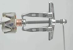
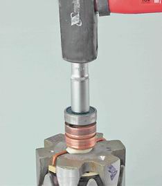
15. If it is necessary to replace the bearing with a puller, press it down from the rotor shaft.
16. Socket wrench by 8 mm with the extension, unscrew the three fastening nuts of the rectifier unit and the stator winding terminals.

17. Removing the two bolts, remove the stator from the cover.
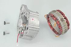
The insulation of the stator winding wires must be without traces of overheating.
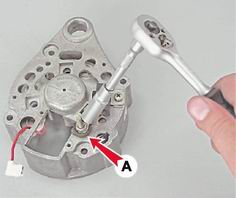
18. Socket wrench on 10 mm with a deep head, unscrew the output nut "30" and remove the insulating washer A.
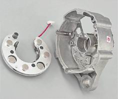
19. Remove the rectifier unit.
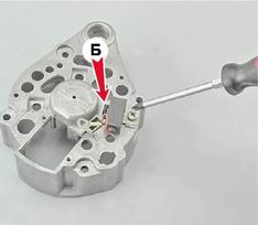
21. Use a Phillips screwdriver to loosen the screw that secures the capacitor and remove it. Remove from the hole in the cover the third bolt B of the fixing unit.
1. We clean the parts of the generator from dirt and dust, blow through with compressed air, wash the metal parts (except bearings) with white spirit or kerosene.
2. Mandrel coinciding in diameter with the inner ring, light blows press on the new bearing on the rotor axis.
3. Check the bearing bores in the covers. Holes should not be deformed, there should be no teasers on their surfaces. If necessary, with a file or scraper, we restore the chamfer of the edges of the holes. Cracked covers are replaceable.
4. The misalignment of the holes in the eyes of the generator covers should be no more than 0.4 mm. When assembling, for the mutual orientation of the covers, we use a mounting bolt and a buffer sleeve.
5. The generator is assembled in reverse order.
This unit is in question.
To provide electric energy for electrical appliances of the VAZ 2105 car, as well as recharge its battery while the engine is running, a generator is present in the car. In the VAZ 2105 until 1987, the units of the G-222 model were installed, and later - the 37.3701 model. In both cases, the generator is a three-phase electrodynamic device, in which the sinusoidal voltage of each of the phases is rectified with the help of the built-in rectifier. This part is a three-phase diode bridge of a VAZ generator consisting of six silicon diodes. The voltage is produced by exciting the rectifier by three stator windings when changing the rotor poles under them. The rotor poles change polarity during its rotation inside the stator, and to increase the value of magnetic fluxes, it has a winding of electromagnetic excitation inside the magnetic cores. The rotor rotates through a belt drive from the front pulley of the engine crankshaft (injector) along with the pulley of the cooling system pump.
The circuitry of the VAZ 21053 vehicle’s electrical equipment differs from that of the model 2105 devices in that it contains an electronic engine control system (ECM) and various additional sensors. Therefore, at VAZ 21053, the power supply system has a different form of terminals than in 2105. Ignition switch of the first model when turning on the starter turns off the secondary circuits and devices.
In general, the generators VAZ 21053 and 2105 are identical. But how to connect the generator to the VAZ 21053, because in this model the injector needs a greater strength of the produced current? And how to connect the generator from the "ten" at 80 A? Fastening, the connection scheme of the VAZ 21053 with it is the same, so there will be no particular problem here.
Features of the device generator

Assembly diagram
The generator housing consists of two aluminum alloy covers, tightened with four bolts with nuts, between which a round stator core is clamped. The rotor bearings are installed in the covers: front - through, rear - in the blind socket of the cover. The rotor rotates inside the stator and the housing on two bearings. At the front end has a slot under the key, thread for the fan nut. An adjusting washer is installed between the front rotor and the front bearing, which is often forgotten to be installed when making repairs to the generator. At the rear end of the rotor shaft in front of the rear bearing, two copper slip rings are pressed together, isolated from the shaft and connected to the ends of the field winding.
Rectifier BPV6-50 is installed to the inside of the back cover. It consists of two horseshoe-shaped aluminum tires isolated among themselves, in which three silicon diodes (gates) of the type BA-20 are pressed into each. The internal bus is isolated from the body, but connected to the bolt of the output "30" of the generator, while the other has contact with the "mass". The legs of the diodes are connected in pairs from each tire with a bolt to the ends of the phase windings of the stator, and their other ends are connected together - a star connection. In the generator G 222 from this point is the wire that goes to the terminal on the back cover, from which the wire goes to the output "85" of the charge indicator lamp of the RS-702 type. In 37.3701 from the common point of the phase windings of the wires there.
To the contact rings of the rotor springs pressed brushes, one of which is connected to the output "B", and the second - with the output W of the voltage regulator mounted on the brush assembly in the upper rear of the generator. In 37.3701 there are three diodes connected at one end to the phase windings, and the second ones are connected at one point, the wire from which goes to the output W of the regulator relay and to the output “61” on the back surface of the generator. The diodes are connected in such a way that they pass positive half-periods to the conclusion "61".
The electronic voltage regulator is not collapsible and since 1996 it has been installed in a metal case riveted to the brush holder. A capacitor is mounted between the housing and terminal “30”.

Generator wiring diagram
To control the battery charge level in the VAZ 2105 car, it is necessary to monitor the output rectified voltage, which is maintained at 13, Jun.14.2 V. by increasing the resistance between one of the rotor brushes and the "mass". When the vehicle voltage is lowered, the regulator lowers the resistance, increasing the current in the field winding and, accordingly, the voltage at terminal “30”. Such cyclic processes occur with a frequency of 50-250 times per second.
The "mass" of the generator is connected to the "mass" of the car through the body attached to the engine block. The terminal "30" of the generator is connected to the terminal "+" of the battery and the on-board network of the machine through the fuse box. The wire from the “zero” of the stator winding that goes to the output on the back cover of the generator G 222 is connected to the terminal “85” of the charge indicator lamp RS-702. The wire from the “87” terminal of this relay through the Ш10 and Ш5 sockets of the mounting block goes to the charge indicator lamp through the connector “2” of the instrument cluster.
In the generator 37.3701, the output “61” is connected by a brown wire with a white stripe to the connector Ш10 of the mounting block and through the connector Ш5 of this block and the connector “2” of the instrument cluster is connected to the charge control lamp.
If the electrical equipment does not work or there are any problems in the on-board network, it will help you find and fix the faults of the VAZ 2104 circuitry.
Symptoms
To determine that there are problems with electrical equipment, you can on the following grounds:
- Charging. The battery charging light flashes, goes out when the headlights turn on. Knocks the jumper in the voltage regulator. When the ignition is switched on, the charging indicator does not light up.
- Motion. Spontaneously increases the speed when driving. Twitching when moving at low speed. Unstable idle. Power loss during acceleration.
- Wiper. Janitors move in spurts. Wipers do not turn on or do not work in rainy weather. Movement wipers jerky.
- Closures The No. 9 fuse blows after turning on the ignition or at the beginning of the movement. Blown fuse number 1. Fuse number 7 burns when turning on the dimensions.
- Dashboard. When the load on the grid devices begin to show incorrect values.
- Start the engine. Do not twist or.
- Lighting does not work.
The main electrical faults: short circuit or open circuit. In the event of a short circuit, fuses, relays, devices blow out, even fire is possible. In the event of a break, either a node, system or device, instrument, etc. fails. You need to be able to understand the wiring diagram of the VAZ 2103, 2104 and other models, find and troubleshoot (video by MR.BORODA).
Carburetor engine
The contact ignition system KSZ is installed on most classic models of VAZ with a carburetor. Since 1987, cars have been completed with a contactless ignition system. The engine for the VAZ 2104 was created on the basis of the power unit VAZ 2103, and accordingly, the circuitry of the VAZ 2103 was used.
Classic ignition
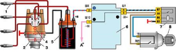
The CSA includes a distributor (2), a coil (5), plugs (1), and connecting wires. The system also includes a capacitor (3), a relay (7), an interrupter cam (4), a mounting block (6), a switch (8).
On machines with KSZ installed distributor 30.3706-01. It is located on the left side of the cylinder block in front of it. Thanks to him, the primary winding circuit is interrupted and the high voltage is distributed to the candles in the required sequence. Distributor consists of ignition timing regulators, high voltage pulse distributor, breaker with contacts.
As the ignition coil is used B-117A with an open magnetic circuit. It is located in the engine compartment and is mounted on the left mudguard with the help of two nuts. The device is used to convert low-voltage to high-voltage. Installed spark plugs A17DRVR serve to ignite the fuel-air mixture in the cylinders of the power unit.
Installed switch type BK347 with anti-theft device. The principle of the anti-theft: when removing the key from the lock in the "Parking" position, the locking rod extends, which locks the steering shaft, going into a special groove.
Electronic ignition
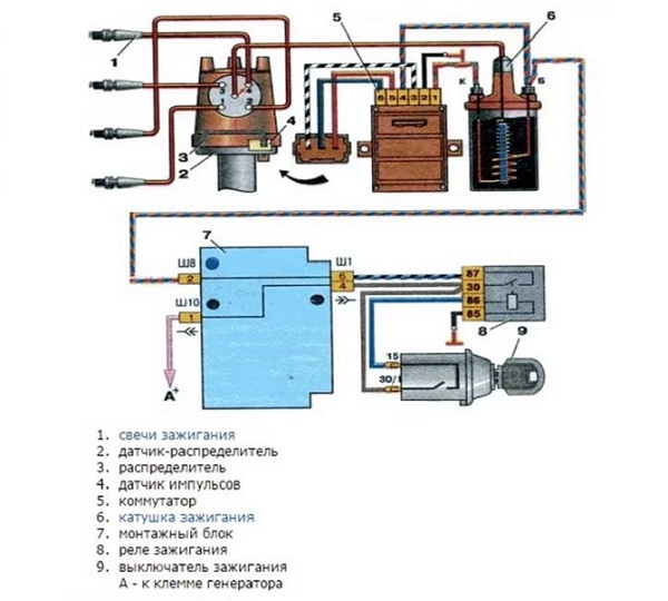
The design of the contactless ignition system includes:
- distributor (distributor);
- sensor;
- the switch that controls the system;
- high voltage coil;
- spark plug;
- connecting and high-voltage wires.
At vases with BSZ installed distributor 38.3706-01, its location coincides with the distributor KSZ. The coil consists of two windings. One connection to the ignition lock relay, and the second through a high-voltage wire with a distributor.
Using wires of small cross section, the coil and the distributor are connected to the switch, which is responsible for the timely supply of the spark. The switch converts the sensor pulses into a pulse current, which is fed to the primary winding of the coil. The coil is also located in the engine compartment, as is the XS coil.
Do not disconnect the wires from the switch if the ignition is turned on. The switch may fail if the battery terminals are removed while the engine is running.
The instruction manual contains the VAZ 21043 wiring diagram of the carburetor with a description of the main components included in it.
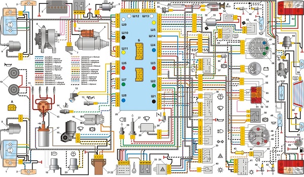
Electrical equipment scheme VAZ 2104
Injector motor
If an injection system of ignition is installed at VAZ, then it is arranged according to one principle.

Thanks to the installed sensors, the controller collects information and, after processing it, controls the operation of the power unit. A special program (firmware) determines the required amount of fuel for each cylinder in order for the engine to work optimally. The injection time and spark formation for each cylinder is determined. The quality of combustion of fuel assemblies is adjusted volume of fuel and ignition timing. At the VAZ 21041 injector the electrical equipment scheme is similar to the VAZ 2104.
Instructions for the diagnosis and replacement of wiring
The task of the electrical wiring of the car is to provide high-quality transmission of electric current to all consumers included in the electrical equipment scheme. If a device or a unit does not work, before changing it, it is necessary to ring the wiring that connects it to the power source and other components of the electrical network.
To check the electrical network you need to prepare:
- Multimeter
- 12 V test light with two wires.
Photo Gallery
 1. Multimeter for testing electrical equipment
  2. Indicator light for diagnostics
If there are problems with electrical appliances, you should perform the following steps:
- Check the voltage. To do this, the multimeter must be switched to the voltage meter mode. One probe of the device must be attached to the mass, which plays the role of the body. The second is connected to the power wire, after removing it from the device or device. If the tester shows the presence of voltage, then everything is in order. If there is no voltage, the source of the fault is located on the segment of the circuit under test.
- Short circuit. In this case, the network is completely absent voltage. To check in the mounting block, you need to remove the fuse and put the tester in the voltmeter mode. One probe must be connected to the terminals in the fuse socket. In this case, all devices included in the checked network section should be de-energized. If while moving the wires on the device the numbers jump, then the wire is shorting.
- Grounding Since VAZ automobiles mainly use single-wire wiring, it is necessary to check the grounding quality, since the body is used as a minus for electrical equipment. During operation, the metal parts of the body are oxidized, rust, and their attachment is weakened. In this case, electrical contact is lost and electrical appliances operate intermittently.
Grounding check is carried out according to the following algorithm:
- Remove the negative terminal from the battery. One multimeter probe connected to the body of the machine.
- The second probe connects to the tested connection or grounding point.
- When values appear on the instrument, verify them with the recommended factory settings. If the values match, then the ground is OK.
Check the integrity of the circuit. This check is required to search for circuit breaks.
The verification procedure is as follows:
- The tested section of the circuit is de-energized: the terminal with a minus on the battery is disconnected or the corresponding fuse is removed.
- To check the circuit, the wires of the multimeter are attached to its ends, and one of the probes is connected to the ground.
- If numbers appear on the display, this indicates integrity of the circuit. If nothing appears on the screen, then there is a break in the circuit.
When replacing electrical wiring using standard wiring or homemade using elements from the standard. You can use wiring from another car, if it is suitable for its characteristics.
For proper selection of wires should be well studied.
To replace the wiring you need to disassemble the front of the passenger compartment. If there is not enough length of the wires, they should be increased. All connections need to be well insulated. Wires are best soldered. It is undesirable to twist the ends of the wires.
Conclusion
Wiring - an important element, which is assigned a responsible role. Despite the fact that the wiring is protected by insulation from mechanical damage and precipitation, it can be damaged during operation. Due to damaged areas, individual appliances or vehicle electrical systems may fail. Therefore, you should constantly monitor its integrity. This will avoid trouble on the road due to electrical failure.
Video "Check wiring control lamp"
How to check the wiring with the help of control, described in this video (the author of the video - Alexander Amochkin Kolomna AAK).