Given in this article homemade laboratory power supplymade of widespread items. It practically does not require adjustment, it works in a wide range of supplied AC voltage, it has overcurrent protection. This laboratory power supply provides an output voltage of 1 V and almost to the value of the rectifier voltage from the secondary winding of the transformer.
Based on the transistor VT1, a comparison module is compiled: from the slider R3 to the base VT1, the proportion of reference voltage, which is determined by the source of reference voltage on the elements VD5, VD6, HL1, R1, enters. The emitter VT1 receives the input voltage of the divider on the elements of R14 and R15. As a result of comparing the reference and output levels, the error signal falls on the base of the transistor VT2, which is a current amplifier, which in turn controls the power transistor VT4.
Work protection homemade power supply
As a result of accidental closure of the output pins of the home-made laboratory power supply unit or when the load exceeds the allowable limit, the voltage drop across the powerful resistor R8 increases. As a result, VT3 opens and thereby closes the base circuit of the transistor VT2, limiting Inagr. at the output of the PSU. A visual signal of an overcurrent in the circuit is the HL2 LED.
In the event of a short circuit in the laboratory power supply, the activation of the mode of limiting the flowing current does not occur immediately. The choke L1 installed in the circuit prevents the rapid increase in current through VT4, and the diode VD7 reduces the voltage surge when carelessly switching off the load from the power supply.
If there is a need to regulate I nagr., Then it is possible to include in the gap between the resistances of R7 and R9 a variable resistor of 250 Ohms, and the engine must be connected to the base of VT3. Thus, in this self-made laboratory block it will be possible to regulate Inagr. 400 mA to 1.9 A.
Details of the laboratory power supply
In a self-made laboratory power supply, it is permissible to use any step-down transformer from Uout. on the secondary winding in the region from 9 to 40 V. The only thing that may be required at low voltage on the secondary winding is to reduce the resistance values of R1, R2, R9, R13-R14 by about two times. And also you need to put the Zener diodes VD5 and VD6 with a different parameter so that the voltage across the resistor R1 is approximately equal to half the voltage across the capacitor C2.
The choke L1 is self-made, wound on a frame with a diameter of 8 mm and has 120 turns of PEL0.6 mm wire. Transistor VT1 (KT209M) can be replaced by KT502, KT209, KT208,. The replacement transistor VT2 () can serve any transistor series. VT4 transistor on KT809A, KT808A, KT803A, KT829 with a maximum ICOL. not less than 5A and the maximum allowable voltage of the collector-emitter exceeding the voltage at the output of the secondary winding of the transformer. Diodes VD1-VD4 - can be any rectifier with a maximum reverse voltage greater than U of the secondary winding and a maximum forward current of more than 5A.
Knot restrictions Inagr. laboratory power supply can be improved. To do this, you need to remove the resistance R7, and instead of the constant resistor R8 set variable. Its resistance is selected so that at the lowest current limiting voltage drop on this resistor was approximately 0.6 V. For the current limiting range from 0.2 to 2 A, the resistance of the variable resistor should be 3 ohms, and the power should not be less than 12 watts.
The power supply unit BP-4A was purchased more than 10 years ago for one self-made project. The passport indicated that protection against short circuits and overheating is. In practice, the power supply unit worked on current modes more than the recommended (2.7 A), step-down transformer easily gave up to 6A current and finally the unit burned down. Since then, he had no luck at all, the stabilizer chips bought for the repair burned one by one and the power supply was replaced with a pulse one and was forgotten. However, direct stabilizers do not interfere with their work, which is very convenient for powering radio equipment. Under the new projects, it was decided to convert the power supply into a laboratory with adjustable stabilized voltage from 3 to 18 Volts and currents up to 5 Amps.
How to make a laboratory power supply do it yourself
A simple but powerful circuit on a field-effect transistor and an adjustable parallel TL431 stabilizer was used for the rework. The power supply circuit is simple. From the old power supply, except for the housing and the transformer, a rectifier with electrolytic capacitors and a radiator are used. All modest piping of the field-effect transistor is placed on a small scarf, but can be easily installed and mounted mounting. The transistor is fixed on the radiator, necessarily through a regular isolation pad. Thermal grease also does not hurt. For ease of installation, the radiator is rotated 180 degrees. See photos and videos. The voltage regulating potentiometer is installed instead of the fuse casing through a 220-volt network. The fuse itself is left inside the case of the power supply. The issue of voltage control is solved by installing an embedded voltmeter (purchased via the Internet). For this, a rectangular window is cut out in the power supply case. Since the supply voltage of a voltmeter exceeded 20 volts, a small radiator is installed on the power supply microchip of the voltmeter. A voltmeter and a voltage adjustment resistor are fixed to the case with hot melt adhesive. A 5000 × 25V capacitor was not installed at the output of the stabilizer due to redundancy and was replaced by a condenser in several hundred microfarads.
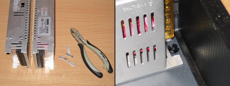
Power supply is disassembled
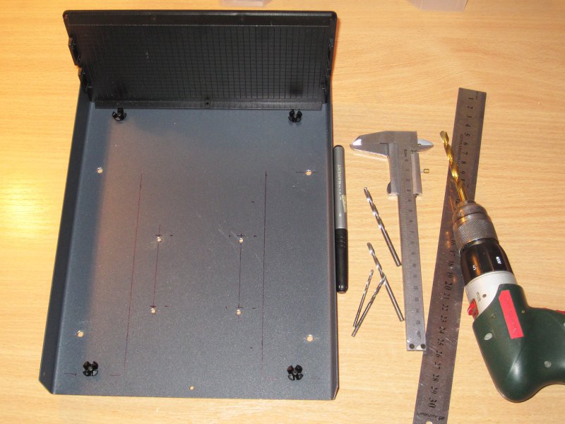
Layout check
Voltmeter is built into the panel
Power supply electronics
When assembling the power supply case, for safety reasons, it is necessary to lay an insulating gasket on the soldering side on the transistor piping board. The field-effect transistor may be of the type IRLZ24, IRLZ34, IRLZ44. For more reliable protection, a 6A fuse is installed on the rectifier board. Field-effect transistors withstand tens of amperes and the fuse is most likely designed to protect the transformer and the rectifier. If an inductive load (for example, an electric motor) is connected to the power supply unit, then it is necessary to connect in parallel to the output of a high-power rectifier diode (anode to +). Tests have shown that the laboratory power supply copes with its tasks.
Do you like the idea of building a laboratory power unit with your own hands? Add instructions to favorites and share the link with friends.
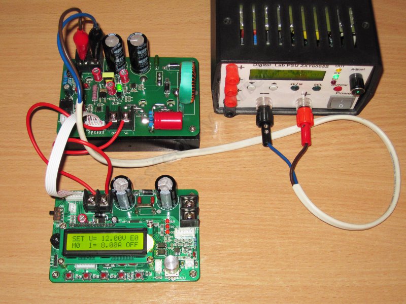
Using the low-end DC-DC converter of the ZXY60xxS family.
The power supply is healthy and works absolutely fine. But the operating experience showed that I want something else. In this regard, about a year ago I decided to design a more optimal (at least for me) power supply.
In general, anyone wondering what I nakolhozil in the end, I ask under the cat.
Attention, great traffic, a lot of photos.
To begin with, I will say that in this review I will often refer to a series of several reviews a year and a half ago, where I reviewed a less powerful version of this board, its application, and additional modules and components that were then used.
In addition, this fee was added to the store's assortment upon my request. Those. The idea of this review was long before the order of this board and even more so before its receipt.
The operating experience of the previous version of the board showed a rather large usability with it, relatively good performance, a large range of output voltage adjustment, but a very small output current.
Yes, the maximum power output of the PSU was 300 watts, this is quite normal, usually inexpensive power supplies have a power of 150-200 watts.
But the maximum current was limited to five amperes, and more precisely 5.2 Amps.
I often have to deal with the repair of all power supplies, as well as automotive step-up inverters. And while it is necessary to be able to adjust the voltage of these inverters to troubleshoot.
And since the output current is only 5.2 Amperes, it turns out that with a voltage of 14 Volts I can get only 73 watts. It is little, very little.
At the time of ordering the previous board, I did not know its features of work, but in the process it turned out that the board has a very convenient feature.
A special feature is the ability to set the maximum output power.
For example, I need a large current at low voltage, but this does not mean at all that I need the same current at maximum voltage. I decided that at a voltage of 60 volts, 5-10 Amps would be enough for me.
Actually, this was the idea that came to my mind a year ago.
This power supply allows at a maximum output power of 700 watts to get more than 300 watts at a voltage of 14 volts, and this is much more than 73 in the previous version, in addition, it allows you to get more than 600 watts at a voltage of 28 volts (24 volts inverters).
So, something I strongly ran ahead, probably it's time to go to the review, and the rest is already in the process of telling.
Inside, everything is carefully shifted with a bubble, on top is a USB-RS232 ttl converter, which I did not even expect.
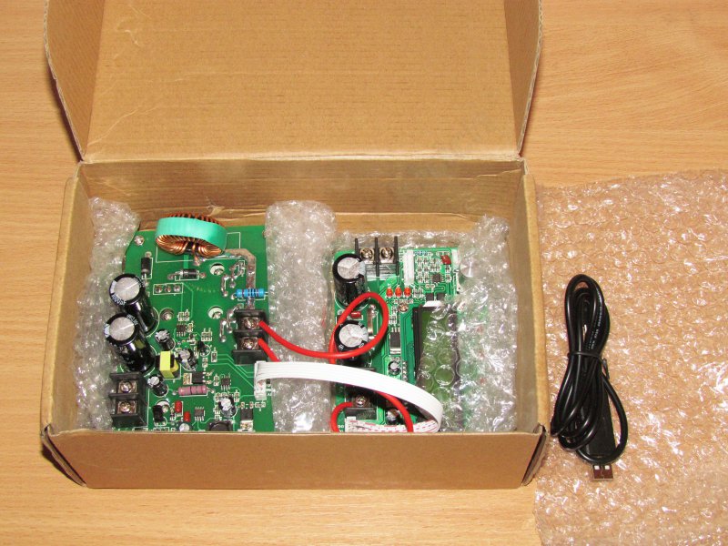
And here is the converter. I would not say that for the declared power it is large, rather the opposite.

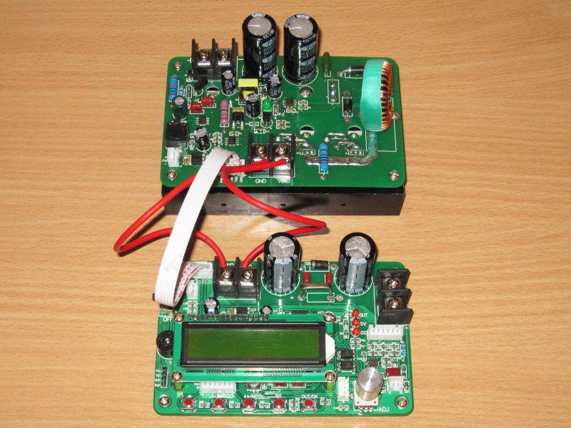
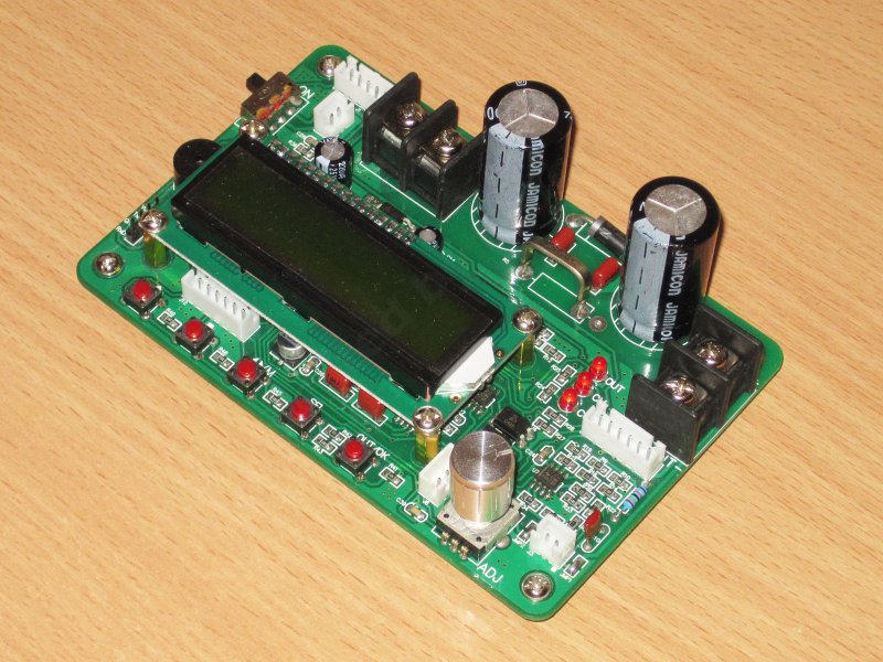
Unlike the previous version of the ZXY6005, this one consists of two boards, however the design of the middle version of the ZXY6010 is exactly the same.
The power unit is assembled on one board, the second is control, indication and current measurement.
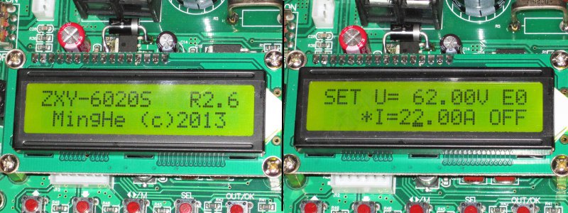
The stated specifications of the converter.
In fact, the maximum output voltage is 62 volts, and the current is 22 amperes, which gives more than 1300 watts.

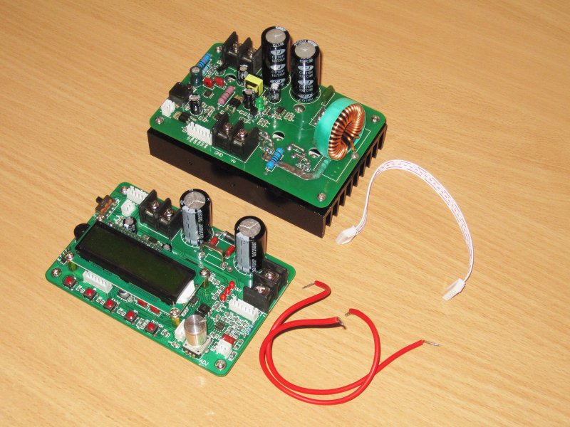
The design is very well thought out, the boards are connected through two lines, power and control. The boards can be easily disconnected from each other, this is really convenient.
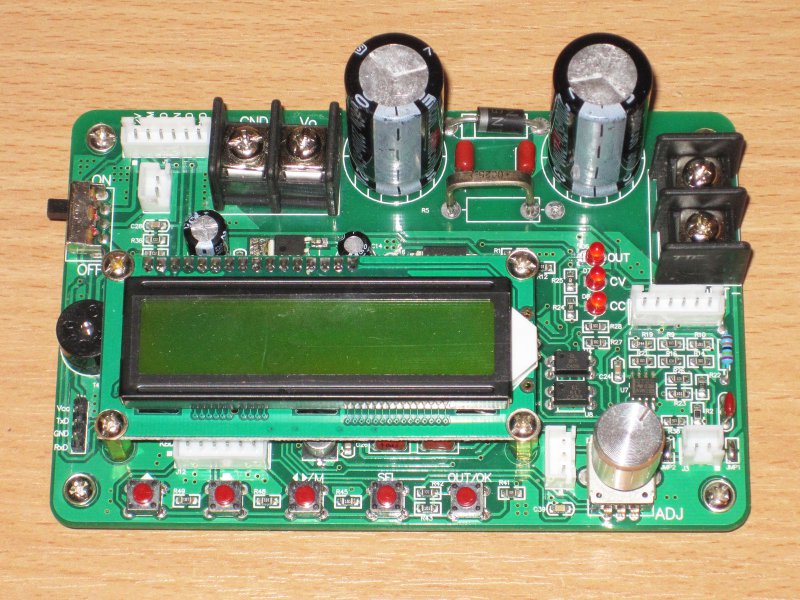
First, I'll show you what the control board is.
Basically, it is very similar to the board ZXY6005, I would even say that it is more than just similar.
The processor node, analog circuitry, control and indication are completely identical, with the exception of some minor points, and of course, the ratings in the current measurement circuit are slightly different.
The main difference is that almost the entire power section and the pre-voltage regulator assembly, which provides 12 volts, were carried on a separate charge.
Pleasantly pleased Jamicon capacitors. Not to say that they differ in some outstanding characteristics, but quite reliable, much better than nameless options.
The control unit, buttons and encoder are completely identical to the younger model of the board.
Terminal blocks really became "fatter", but this is understandable, the current up to 22 Ampere imposes its own requirements on the components.
On the back of the board is empty, in general, no components, only the conductors of the printed circuit board and that's it.

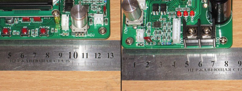
Since the boards are designed to be installed one above the other, the dimensions of both the boards are the same and amount to 130x85 mm.
The control buttons are located at the bottom of the board, the functions are the same for all boards.
1, 2 - increase / decrease, as well as the choice of display mode.
3 - select a memory cell or move the cursor when adjusting parameters
4 - choice of adjustable parameter
5 - turning on / off the power supply to the board output, as well as confirmation of the choice of parameters.
As well as in the past version there are two uncomfortable moments:
1. The ± buttons are unusual for me, increasing on the left and decreasing on the right.
2. buttons to connect to the input of the ADC, but a very small range of voltage changes from pressing the buttons is selected, so do not forget about the presence of the keyboard calibration mode.
Calibration - turn off the power, press the OK button, turn on the power, when the calibration value is displayed, then release the button.
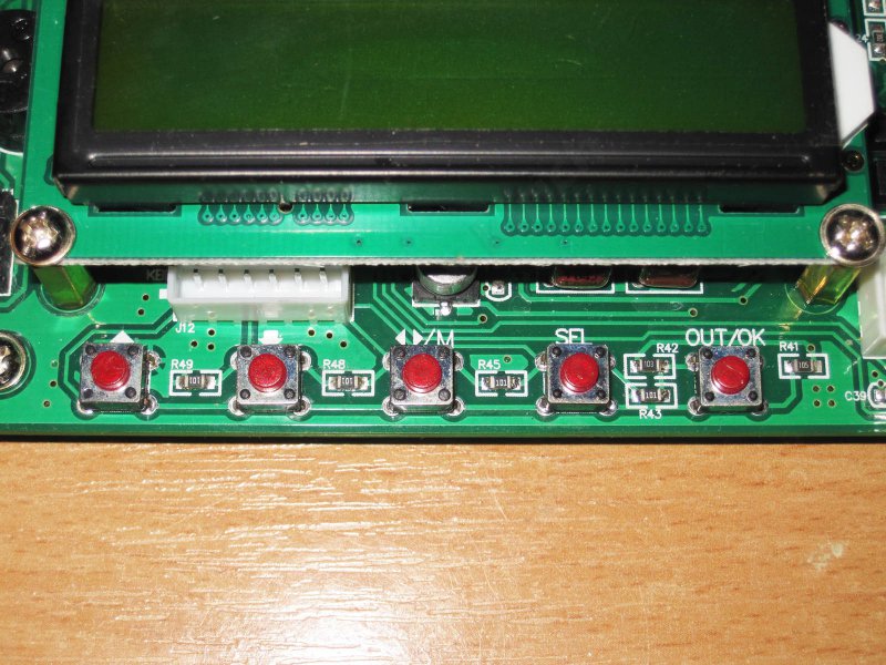
To the right of the keypad is the encoder, which essentially duplicates the ± buttons, except for the choice of operating mode.
On the left is a connector for connecting to a computer, a rather useful option.

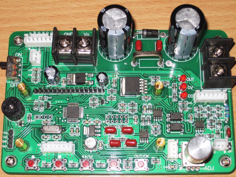
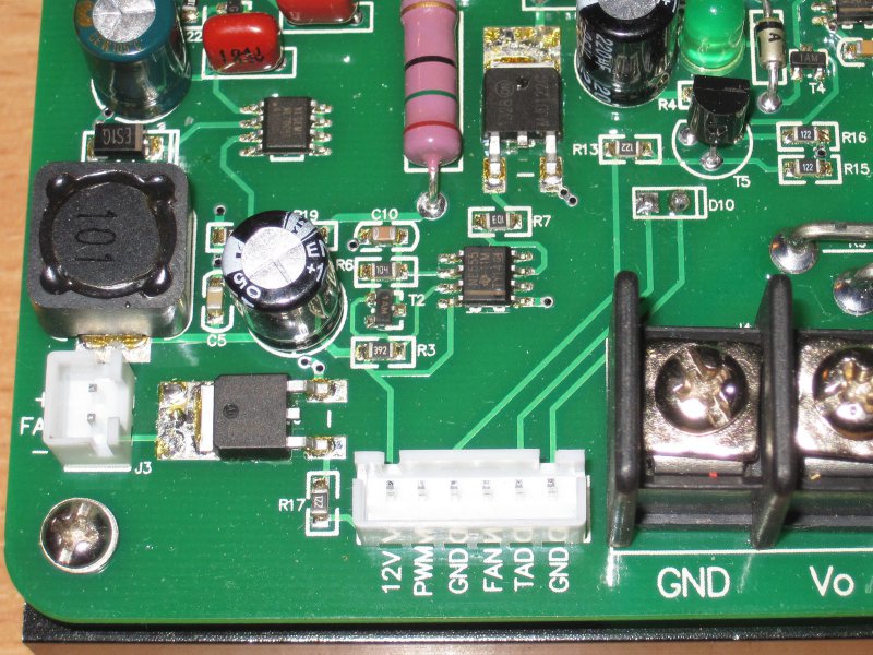
Part of the components is hidden under the display, which can be removed after unscrewing the four screws.
Since the converter is quite complex, and the installation is one-sided, the layout is dense.
immediately striking the presence of a large number of connectors.
At the top left there is a connector for connecting the board to the power module, beneath it is a duplicate power switch.
At the bottom left there are connectors for connecting to a computer and for an external keyboard.
At the bottom right there are two small connectors, three-pin for connecting an external encoder, two-pin for connecting voltage feedback.
Top right connector for connecting the LEDs indicating the operation mode.
1. This board uses a microcontroller STM8S105K6T6C, the younger one was STM8S105K4T6C
2. The microcontroller is powered by the AMS1117 linear stabilizer with an output voltage of 3.3 volts
3. The analog part is made identical to the previous board, but other operational amplifiers are used. The last time was the OU from Microchip, now the precision instruments from Texas Instruments are installed.
4. Instead of controlling the PWM controller, XL1509 is installed more powerful.
This controller controls a powerful transistor mounted on the power board.
The frequency of 150 kHz.
5. On the board there are three LEDs indicating the operation mode.
Output voltage applied.
BP operates in voltage limiting mode
BP operates in current limiting mode.
6. It all feeds from a 5 volt linear regulator (operational amplifiers are applied with 5 volt power).
In general, it should be noted that the device is fully functional "out of the box", i.e. The board contains all the necessary controls and displays.

In addition to the "fine" electronics, the control board contains capacitors of the output power supply filter and current-measuring shunt.
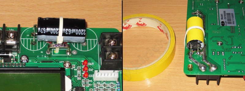
Capacitors have a capacity of 2200 uF and are designed for voltages up to 63 Volts.
The voltage is chosen right next to it, with the output voltage of 62 volts, it is a little unsafe to install 63 volt capacitors.
Also in the photo you can see large terminal blocks for connecting power wires, terminal blocks are good, there are no comments.
Judging by the designation and my estimations, the shunt has a resistance of only 2.5 mΩ.
I was not sure about the labeling, or rather in the order of numbers, because I spent a little calculation on heating.
At 2.5 mΩ on the shunt, a power of about 0.0025 x 22 x 22 = 1.21 Watt will be released
At 25 mΩ it would be about 12.1 watts, and since the shunt is a bit warm, the first option is suitable. 2.5mOhm
The connector for connecting the power board has only six contacts, of which two are earth contacts (I will explain later why).
The remaining contacts are
12 volts to power the control board
PWM signal to control a powerful transistor
Fan control
The signal from the sensor.

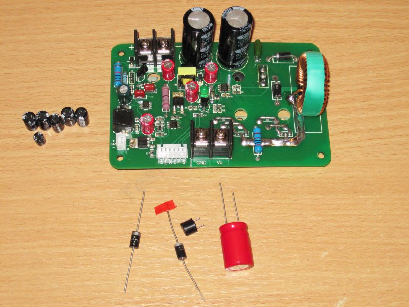
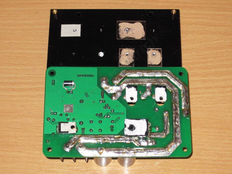
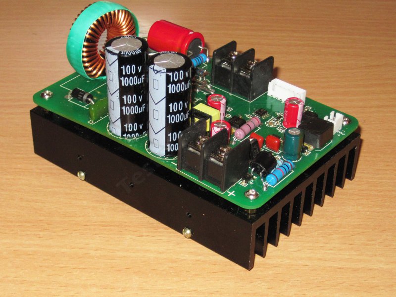
Power module
Here the layout is obviously more free, most likely the control board size was simply chosen as the basis, and then the power module was made to the same size.
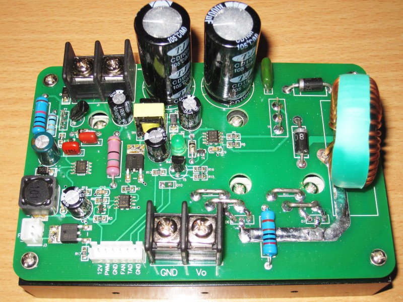
The board is bolted to a radiator of a decent size, on which transistors and diode assemblies are placed.

It should be said separately about one of the useful improvements to the board.
The fact is that in previous versions of the board the power was realized by converting the input voltage to the secondary 12 or 5 (on the 6005 board) using a PWM controller.
There were many comments to such circuitry, since the reliability was very low. I have repeatedly met the mention of the failure of these converters.
The fact is that the board is better to feed at least 65-70 volts to the input, and this is already a rather heavy mode for operating inexpensive PWM controllers. In my 6005, I replaced the controller with a more expensive one and used some modifications to reduce the voltage, but it is expensive and difficult.
Here, the manufacturer first put a linear converter at 54 Volts, the output of which is connected to the filter capacitor through a resistor to reduce the inrush current, and the 12 Volt converter is already further.
Those. the circuit looks like this - Input voltage - linear stabilizer 54 Volt - PWM stabilizer 12 Volt (fan and power electronics) - linear stabilizer 5 Volt (operational amplifiers) - linear stabilizer 3.3 Volt (processor).
For this special thank you very much. By the way, there is still an old photograph in the datasheet, without a linear stabilizer.

On the power board, there is also a connector with the same pinout of the contacts as on the control board, with the power terminal block next to it.
1. As a PWM controller, lowering 54 Volts to 12 is applied. It has a maximum input voltage of 65 volts, because 54 volts for it is very much with a margin.
But it is worth considering that the output current is a maximum of 0.5 Amperes, therefore you should not connect powerful consumers to this source. It also has not very reliable protection against short-circuit, which I checked on the last board with a bad result: (
2. Fan power is switched by a bipolar transistor.

Also, the driver has a powerful field effect transistor installed. Those. This is essentially a cascade for controlling the power switch included in the positive power wire.
I did not understand the scheme, but I will only say that a somewhat non-standard solution is used here, I usually use more familiar top-level drivers in such nodes.
The purpose of the LED for me also remains a mystery.

The driver uses two widely known timers. One is connected to a pulse transformer and controls the transistor to which the transformer is connected.
The second timer is set in the “upper” part of the driver.
Strange, incomprehensible, but it works :)

The choke looks very small, especially considering the fact that the board has a maximum output power of 1200 watts.
Although given the fact that the manufacturer recommends the use of active cooling, it is possible and normal. But I would still increase its size (taking into account the constant inductance) and apply a wire with a larger diameter, this would definitely improve the thermal mode of operation.
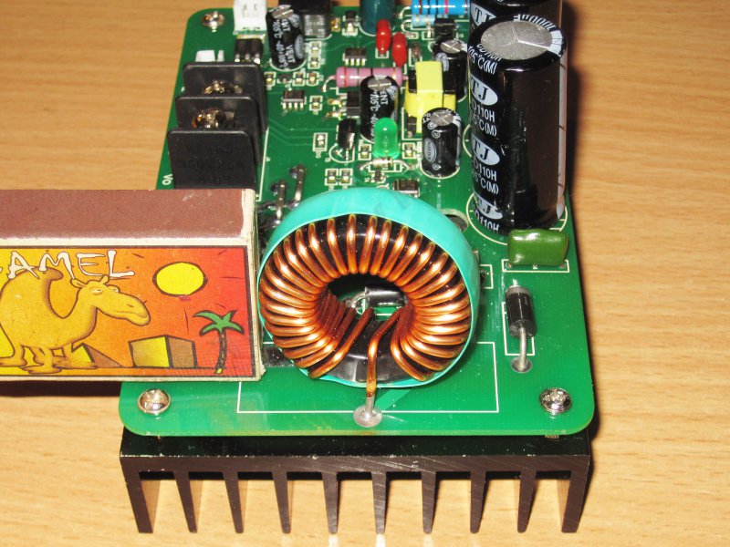
Here, the capacitors are already used with a reserve, the last time the input capacitors were also at 63 volts.
There are also two installed at 100 volts with a capacity of 1000 μF.
Next to them is a terminal block for powering the board.
To the left of the capacitors is a diode connected in parallel with the input to protect the card from polarity reversal. The benefits of high currents from it are small, but in extreme cases it will burn and short the power, thereby protecting the electronics.
Near the power choke there is a second diode, it is connected in parallel with the power transistor.

Remove the fee, the benefit for this is only necessary Phillips screwdriver, convenient :)
All elements are installed through heat-conducting gaskets, i.e. the radiator does not have any electrical contact with the elements and can be attached to the metal housing.

On the radiator are derived:
1. Thermal sensor
2. Two diode assemblies STPS20H100C, each designed for current up to 20 Amps (for the entire assembly) and voltage up to 100 Volts. Since there are two assemblies, the maximum current is 40 Amps, this is without a margin, since for a good diode current should be 2x from the output.
3. But as a powerful key, there is unexpectedly a IXYS transistor. This company produces very good power elements, because the presence of a component of this company is very nice.
Mounted transistor marked. This is a powerful N channel field effect transistor with a maximum current of 160 Amps, a voltage of 150 Volts and an open channel resistance of 9mΩ.
4. Unfortunately, I failed to identify the transistor of the linear stabilizer of 54 Volts, the marking was either absent or completely erased :(
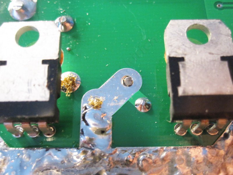
Since not all the elements turned out to be unbendable, the transistors had to be soldered, at the same time he noted that the field effect transistor was soldered to the board “against the stop” and then slightly bent off the board.

Naturally not done without modifications.
In principle, the motherboard improvements have been done a lot, and I will describe all these improvements.
But I will also say that the board is fully operational without these modifications.
The purpose of the improvements was to improve the reliability and quality of work. and reliability was in the first place. And just since I started studying, I could not resist in order not to change something for the better.
First of all, I took the 0.75mm.kv wire and strengthened the power paths on the board, passing it along with a lot of solder.
The average current through these tracks can reach 22 Amperes, and the pulsed one all 44 Amperes, therefore by increasing their cross section we get a small, but improvement, all the more it is easy.

Diode assemblies are connected through small equalizing resistors, I cannot measure their resistance, but the fact that these "jumpers" are even where you could draw a track simply indicates that these are all low-resistance jumpers in the form of jumpers.
This decision is correct, but in some places these jumpers were not well soldered, at least it seemed to me, because they were also later soldered.
The following revision concerned the replacement of capacitors with better ones, I used good Capxon KF series capacitors.
Replaced were 4 capacitor 220mkF 25 volts for capacitors with similar parameters.
After that, I prepared additional elements that were not originally on the board, but it would be better with them.
Some improvements that are useful to make in the scheme of the power board.
First, improving the "protective" properties of the board.
1. Cut the track near the input terminal block. The path comes from a small protective diode, which does not transmit power if polarity is allowed on the input.
2. We solder the fuse into the gap of the cut track.
3. I applied a fuse for a current of 315mA. The current consumption of the board varies depending on the input voltage and is about 200-80mA. The higher the voltage, the lower the current.
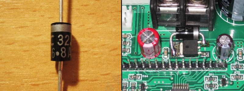
4. Along the way, for protection, I bought a 1.5KE13A suppressor; this is essentially a powerful 13 Volt zener diode.
5. This suppressor is soldered parallel to the output capacitors standing in the 12 volt circuit, after the PWM stabilizer.
His goal is to prevent the voltage from rising when the PWM controller of a 12-volt power controller is broken, and also to burn the fuse. This is done to protect the board's “brains” in an emergency situation.
6. I also installed a 220V capacitor 100Volt parallel to the power output of the board.
The fact is that the wire from the choke has a long length to the filter capacitors and interference from large current surges is possible.
In the previous revision of the board, there was a capacitor here, but then it was transferred to the control board. I decided to do it my own way and installed an additional capacitor on the power board. Its capacity is small, but it definitely does not hurt.

Well, this revision is more likely from the series - why not do it once there is an opportunity.
I replaced the heat-conducting rubber gaskets with mica gaskets.
Some time ago I did a review where I compared the thermal conductivity of various gaskets and mica proved to be better than rubber, so it was decided to change.
Laying under the transistor of the linear stabilizer 54 Volts did not change as the heat there is small.
Additionally, I missed the KPT-19 paste, as I understand it, it has slightly better characteristics than the popular KPT-8.
![]()
This is how it looks after the modifications and before twisting the board and the radiator into one block.
At that time, I did not think that I would have to disassemble the structure again.
1. One of the conclusions of the power choke is a jumper between the layers of the board.
Those. the track goes on top of the board, but at the output point switches to the other side. I decided to solder this place in order to reduce the current load on the metallization of the board holes.
2. Type of replaced and added components.
![]()
General view of the board after the first stage of improvements (I did not think that there would be more than one stages of improvements).

The management board has also been modified, albeit to a lesser extent.
1. A suppressor was also bought here, but this time it is 1.5KE6.8A, designed for 6.8 volts.
2. This suppressor is connected parallel to the 5 Volt bus to protect, if not the operational amplifiers, then at least the processor.
This suppressor is installed in case the first stage of protection does not help.
The fact is that it is possible to replace operational amplifiers, a PWM controller, transistors and diodes, but the death of the processor is definitely a charge in the garbage, and since the board is not cheap, I would not want to do that. Last time I already had a breakdown of the stabilizer, the processor survived, but I definitely added gray hair.
Trial inclusion after alteration.
In general, I experienced a bit of a fee and before the alteration, but due to the fact that the review was prepared for a very long time, the linearity of the chronology of the photographs was violated, therefore I will publish the photos in not quite the correct order, sorry.
The first inclusion made from the previous BP, just for convenience.
When turned on, the screen briefly displays information about the model and manufacturer of the board, as well as the version number of the firmware.
After this, the menu for voltage and current selection is displayed.
By default, the board is set to 12 Volt 5 Amps, but if you wish, you can change this to any other.
It would be more accurate to say that at first the board is turned on with the settings specified in the M0 memory cell, and then you can either select the required parameters or the required memory cell (10 cells in total) with the parameters already configured (the rest of the cells are empty)
The maximum can be set to 62 Volts and 22 Amperes, so it would be more correct to call the fee 6222, but the manufacturer decided to round the parameters down and called the model 6020.
After checking that the board is working, I moved on to further refinements.
The power lanes were also strengthened on the control board, but an important digression should be made here.
The fact is that due to the low resistance of the shunt, the accuracy of the current measurement is also influenced by the increase in the cross section of the tracks in places (or rather in one place) near the shunt.
One of the shunt pins (closest to the output from the board) is connected correctly, there is a power track on the bottom of the board, there is a signal track on the top, therefore, soldering does not have a particular effect on the measurement correctness.
But the second one is more critical for refinement, if you don’t want to do recalibration, then it’s better not to siphon a place closer than 5mm near the shunt.
In general, propayka does not affect the accuracy of the measurement, but the resistance, you can solder as you like, but then it will be necessary to calibrate the current setting and ammeter readings, I decided not to calibrate and simply did not solder this place.

Further alterations did not concern the replacement of elements, but their rearrangement.
For this, I had to drop out large capacitors, at the same time I measured their capacity, there was no “underfilling”, everything was fine. The photo is hard to see, the capacity is 2290µF with the declared 2200.
For good they should be replaced with capacitors with a voltage of 80 or 100 volts, but this will be done another time when I pick up something suitable.

Alteration was to reinstall the capacitors in the "lying" position, it was a necessary measure due to the characteristics of the case in which I was going to install it all.
The capacitors were fixed with a coupler in the holes drilled in the board, there are few tracks, so you can drill holes without problems.
At the same time I erased the marking from the shunt, I had to apply it again with a marker :)
To fix the board in the case, I used four small parts, though the thread was 2.5 mm in diameter for fasteners, and under the standard 3mm screws of the house there was only a couple of corners.
Well, since it is correct to use one type of fasteners of the same type in fasteners, I decided all four corners under 2.5mm
![]()
The fastener is made so that the radiator is slightly elevated above the surface, this slightly improves the air passage and facilitates the screwing process. The corners are installed inside the shelf so as not to occupy too much space from the sides of the radiator, and safety is slightly increased (do not stick out the screws) and aesthetics.
But on racks, through which one board will be attached to another, I decided to save a little.
It was possible to put conventional mounting racks with M3 threads, but in my storeroom there were tubules with an internal hole 3 mm in diameter. The tubes were from Polish-made log-periodic antennas and come across the markets.
On the one hand, the threaded tube has an M3 thread already installed, which makes it easier.
On the other hand, I screwed the rack from the computer cases. They have an external thread slightly larger than 3mm, and an internal M3.
I think the process is clear from the photo, we clamp the tube in the screwdriver cartridge, we hold the stand with pliers and twist it at low speed, it is very convenient.
The result was such neat (well, almost neat) small stands :)

Screw racks instead of mounting screws of the power board.

Next, install the board "sandwich".
The height of the racks is chosen so that there is a small distance (5-6 mm) from the top of the capacitors to the bottom of the top board.
There was a version of the assembly, when the control board is reversed, the parts are down, then the capacitors can not be re-soldered, but I was aiming to make a device that is easy to maintain and, if necessary, repair.

So look at the design from the side, you can see the distance between the large capacitors of the power board and the control board.
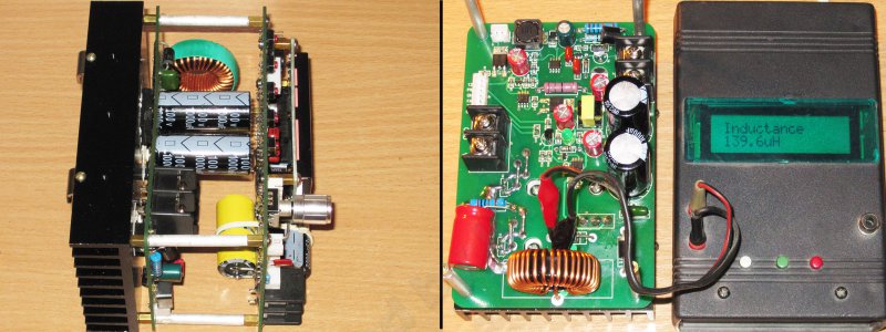
When I was tinkering with the finalization of the power board, I forgot to measure the inductance of the power choke, so while there is an opportunity, I decided to correct this error.
For measurement, I sealed off the capacitor connected to the output so that it does not affect the measurements.
The device showed 139.6mkGn, I think this information may be useful in finalizing the board with the replacement of the power choke.
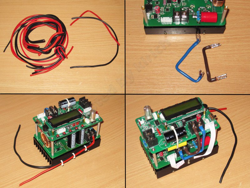
The design is assembled, it is time to move on to the electrical connections.
I did not like my own power wires, the cross section was about 1-1.5mm.kv, but the quality was not very good, so it was decided to change it.
For this (and not only for this), wires of increased flexibility of different sections were bought, I bought each pair (red and black), 2.5-4-6mm.kv, each meter, I don’t remember how much they cost, but they didn’t very budget.
And although the soft wires were bought, I made the interconnect power connection with a 6mm.kv rigid wire, it was convenient to bend it under the necessary configuration and it turned out to be even more suitable for this.
I took the wires to the power supply units with a 2.5mm section, the current in this circuit will not exceed 11 Amps even at the maximum.
Well, in the last turn, I fixed the control wires, just so that they do not hang out like horrible :)
I think it is worth a little distraction and tell about the choice of the case, as it influenced the changes in the design of the power module, and the choice of components.
Since the device was planned to be powerful and rather heavy, I immediately rejected the idea of plastic cases.
I wanted a metal case, preferably durable and beautiful.
The choice of such cases is very scanty, and it’s almost impossible to choose a specific task at all, because the first thought was to buy an old oscilloscope or some other faulty device, throw out the stuffing and bring a marafet to make it look beautiful.
A search on flea markets and forums showed that there is a choice, but either they are absolutely terrible, or do not fit in size, or have an unbearable price.
I eventually climbed onto Ali and, in principle, very quickly found a suitable housing, but the price was not pleasing. It is understandable, to buy such things in China is very expensive because of the price of delivery.
What was my surprise when I decided to find the same building in our online stores, and found in Odessa, at a price noticeably lower than in China :))))
He then came to me about $ 30, taking into account the price of delivery in Ukraine, but I received it in a couple of days.
The case is really gorgeous.
Dimensions - 220 x 275 x 120 mm - on this case and on options.
Remarkably and very conveniently, the case is not symmetrically divided, the upper cover is larger than the lower one in height, this gives more convenience during installation. The case is strong, the front and back covers are fixed tightly, nothing backlash.
The set gave a handful of black screws. The top cover is screwed on 8 screws, the lower one on 6, 4 screws were given in stock.
Conveniently, you can easily remove the front and rear panels; it is removed not upwards, as in plastic cases, but forward or backward.

I also made a small foray into the radio market, where I bought all sorts of connectors, wires, a fan, a grid to it, and just different small things. In the photo, a part of the purchased one, the rest has already been bought up “in the course of the play”.

One of the things I bought was a bunch of capacitors that I needed to refine the power supplies.
I already did, this is a power supply unit at 36 volts, 10 amps, 360 watts.
In principle, the PSUs are not bad in themselves, but once I sat down at the assembly, I decided to immediately finalize them, just in case.
For them, 6 1000 mkF 63 Volt capacitors and four 220 mkF 25 Volt capacitors were purchased.
Also found at home a pair of capacitors 100mkF 400 volts.

The first two types of capacitors (220 microfarads and 1000 microfarads) were simply installed instead of those that were, but to install a 100 microfarad 400 volt capacitor, I had to remove the input voltage range switch.
Installed capacitor in the photo above.
He had to bend the negative conclusion, but everything turned out fine. In a review of this power supply, I wrote that it would be nice to increase the capacity of the input electrolytes, as the manufacturer installed them with an underestimated nominal.
This capacitor is installed parallel to the output from the diode bridge.
To install the capacitor, a pair of holes were drilled in the board, the tracks were cleaned and the leads were soldered there.
The photo shows where to solder. I do not think that in other BP something is globally different.
![]()
But it was not all alterations.
Attention. With a serial connection of any power supply units in the iron casing, make sure that the negative output contact is not connected to the power supply housing, otherwise unpleasant surprises are waiting for you!
Since the power supply is connected in series, to protect them, install diodes parallel to the power supply output.
I chose the diodes from the old stock, 2D213, though I did not need mounting washers.
Long thought where to pitch them. In principle, it was possible to put them in the place of the missing diode in the output rectifier (the place for two diodes is one).
But I wanted a collapsible design.
Therefore, I installed the diodes on the bottom of the printed circuit board, and according to the idea, the diode should be pressed against the aluminum case by the board itself.
Since the plastic insulator was laid at the bottom of the power supply unit, a hole was cut in it.

He did everything, laid an insulator from mica, screwed up the board, and found out that the diode is not pressed tightly, or rather, it is not pressed.
I had to get out of stocks thick heat-conducting rubber (1.5mm), which I had already reviewed and used it.
Since this diode works for a short time (in the case of a force majeure) and even in the worst case it does not dissipate more than 10 watts, then this option is acceptable.
He gathered everything back to the group, but at the last moment he remembered that at one of the power supply units of this company (48 Volts 5 Amps), the diode assembly was crookedly pressed.
There were no particular problems here, but I decided to play it safe and laid a small piece of metal to improve the quality of the clamp.

The first fitting of power supplies and converter boards in the new package.
I think now I understand why I reworked the control board and put the capacitors on its side.
In general, it was possible not to do this, the entire assembly was normally installed either when the control board was upside down, but this was inconvenient, or when it was standing like now, but with vertically mounted capacitors, but it was not safe, since everything was literally zero. .
Considering the above reasons, I decided to lay the capacitors on one side, and at the same time slightly raise the module above the bottom of the case, it seemed to me better.

In the process of fitting it turned out that the power supply units cannot be installed close to the back wall, I interfere with the legs of the case that protrude inside.
Even though I had a place, I didn’t want to spend it, so with the help of side cutters I modified the BP case a little.
If you modify as well, then do not throw away the bitten pieces, they can later come in handy.
Then everything went according to the usual plan, placed the power supplies and the converter module in the case so that it was convenient and did not interfere with anything, marked the holes, drilled, removed the burrs. One hole didn’t coincide a bit, then I had to drill out, but otherwise everything is fine.
I mounted the power supplies and the module in the case, hoping that I would not take it out.
For power supplies, two screws are enough for each; they are held tightly.
The design was thought out so that the power supply fans captured the air around the air vents of the case, and the PSU bodies themselves formed a kind of “corridor” through which the air flow generated by the exhaust fan on the rear wall of the case passed.
The power supply unit does not reach the top of the casing approximately 5mm, it is possible to improve the design by paving something elastic along the top wall of the power supply casing, then the air will be blown out better, but I did not do that.

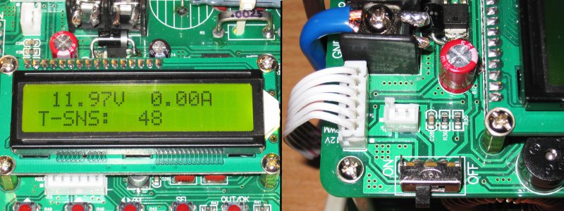
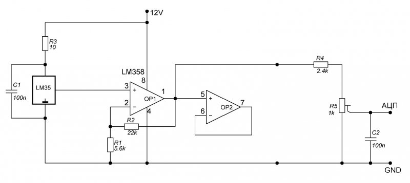
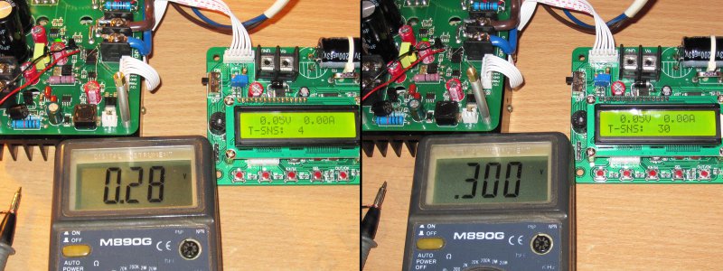
During experiments with the module, I found out that it can display the temperature of the radiator, at least there is a T-SNS function, and in the settings menu there is an option for emergency shutdown at a user-defined temperature.
But on the screen there was only the value 48 and it is not written that 48 (just like in the well-known joke).
I didn’t think for long, I screwed the whole structure and installed it in the case, thinking that it’s okay, then I’ll adjust it, I even took a photo before the adjustment and a photo of the place where I will change the values of the resistors.
But the reality turned out to be both harsh and completely meaningless, the ingenuity of Chinese engineers is sometimes amazing.
Will explain.
I plugged in instead of a single resistor trimmer and tried to adjust, putting approximately the ambient temperature, I began to heat the radiator.
but the values on the screen varied maximum within a couple of characters. O_o
The first thought is that the sensor is faulty, the second is not the sensor at all.
But it turned out that I just casually read the datasheet.
And now attention, we are trying to understand what Chinese engineers have come up with.
The screen displays abstract numbers in the range of 0-255.
Moreover, these figures are inversely dependent on temperature, i.e. higher temperature - less value.
They vary within very narrow limits.
But in the datasheet they wrote, they say this is a feature, to find out the temperature, it is necessary to recalculate it from the base 50, then we consider the inverse relationship, provided that a certain number of values are calculated per degree.
Can you imagine this process? A person is sitting, trying to find out how many degrees are on the radiator, for this he knows the dependence of values on temperature and calculates.
But this is tied to the automatic shutdown, I had a shock.
Well, okay regretted the normal sensor, but at least a thermistor, but why not bring it all into the program?
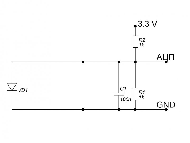
Understanding the temperature measurement, I found that to change the values on the screen in the range of 0-255, you need to change the input voltage from 0 to 3.3 Volts.
Those. it is easy to measure the total voltage from the ADC input and recalculate taking into account 8 bits of resolution.
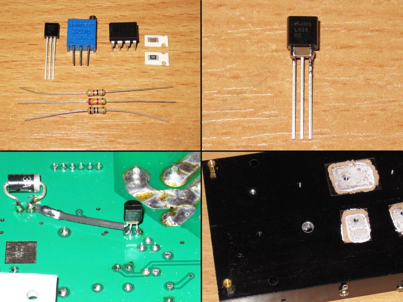
After that, I began to look for some convenient thermal sensor.
At first, I wanted to use the same diode or thermistor, but I wanted to leave the sensor connected between the ADC input and the ground, which meant that it was necessary to apply - an inverting large-scale amplifier with offset. This is difficult to pronounce, not what to use.
All options were bad and categorically did not suit me.
I wanted a simple, convenient and most importantly - repeatable solution.
An output was found; there are special analog temperature sensors that output a voltage in the range of 0-1 volts with a temperature change in the range of 0-100 degrees. As for me, in this case it was mega-convenient.
Another campaign on the market, another purchase of every small fry.
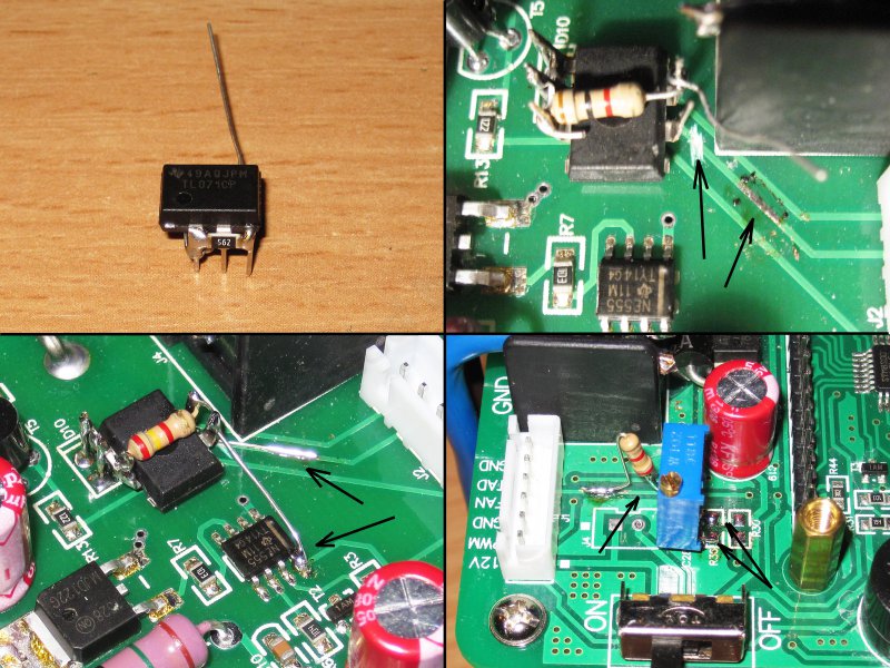
1. I bought a sensor (a bit more expensive than a dollar), a pair of operational amplifiers and a trimmer resistor.
2. The location of the sensor leads is such that the extreme leads are power, and the middle one is the output.
Just in case, I soldered a capacitor in parallel with the power supply to the sensor, soldered directly to the terminals of the sensor.
3. Soldered the sensor with two feet to the board, and the third filed 12 volts from the capacitor on the board before I soldered a protective suppressor there). Power supplied through a 10 ohm resistor, for at least a small, but reducing interference from PIMA 12 volts.
4. For the sensor, ream the existing hole to a diameter of 5.5mm, fill it with paste and set the board in place.
At first I did not want to publish the pictures of the unsuccessful version, but since in the process the pictures were altered, they will have to be attached.
The first attempt was with an op amp TL071, this is a single-channel amplifier, it was more convenient for me, but it did not work.
I just wanted to increase the voltage from the sensor to an arbitrary value, well, for example, 5 times, then a divider with a trimming resistor can already get the required value.
Moreover, the OU was located near the sensor, and the divider with the trimmer near the processor.
By the way, for the connection of the control board with the power board, two earth wires are used, one power, and the second only for the sensor, from the point of view of measurement correctness is a very correct decision. A fall on power ground does not affect the signal from the sensor.
So.
1. Prepared an amplifier chip, soldered a pair of resistors.
2. Cut the signal path on the power board
3. I soldered the microcircuit, I took the power directly from the output of the nearest NE555 microcircuit, the output connected to the cut track.
4. The trimmer resistor was soldered instead of the divider from the resistors on the control board, the capacitor left (the solder of the trimmer was soldered to it).
The third leg of the trimmer resistor is connected via a fixed resistor to the output from the power board.
If you install a trimmer resistor as in the photo, then when you rotate to the right, the readings will increase, to the left - decrease.
And it was not clear that the output. Moreover, the voltage even at the contacts of the thermal sensor did not correspond to reality.
I checked the installation, everything is fine, checked again, everything is fine again.
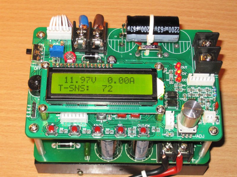
After that, it was decided to apply the classics, LM358.
The general scheme turned out like this.
Unused op-amp is turned on just in the single gain mode, but in the future I think to use it as well.
Resistors again soldered directly to the findings of the chip.
Solder the resulting structure in the same place, connect to the same contacts as the previous chip.
Everything is working:))))
Initially, it showed something abstract, but this is normal.
The adjustment process is extremely simple, we connect the multimeter to the outputs of the temperature sensor and expose the same values on the converter screen using a trimmer resistor.
For example, on a multimeter 0.3 volts, it means 30 degrees. If it is 0.26 Volts, it means 26 degrees.
Practice has shown that even though the sensor consumes very little, it still has a little self-heating, after a short time the temperature rises by 2-3 degrees. In principle, nothing wrong with that, you can either adjust the trimming resistor, or score.
And now about the free element of the operational amplifier.
I was hoping that the board knows how to control the fan depending on the temperature, but it simply turns it on when the output is active (supply voltage to the board output), well, it starts for a few seconds when it is just turned on.
Automatic adjustment of revolutions, in principle, there is, but it works in a completely incomprehensible way, at least I did not understand how. For example, the fan speed may change slightly when the overheating protection parameter is changed, therefore in the future I plan to modify the circuit by adding speed adjustment depending on the temperature, using data from the installed sensor.
.
A brief description of the menu converter.
1. The primary menu for the selection of current and voltage.
2. Calibration of the reference and voltage measurement.
3. Calibration of reference and current measurement
4. Setting the threshold for automatic shutdown when overheating.
5. Minimum 0, if this value is set, the function is disabled.
6. Maximum of 255.
![]()
1. Select the maximum output voltage limit.
2. If set to 0, the function is disabled.
3. Select the maximum output current.
4. If set to 0, the function is disabled.
5. Select the maximum output power.
6. If 0, then disabled, the maximum can be set to 1320 watts

1, 2 Since the board can work as a charger, you can set a limit on the capacity given.
3. 4. And also you can limit the time of the converter, well, or the time of charge.
5. Saving data
6. Automatic switching on of the output with the set value at power on, initially disabled.

1. Restoring all settings to the initial state (resetting user calibrations, clearing memory cells)
2. Mute (assigned to each memory separately)
3. Saving parameters in a specific memory cell (total 10)
4. Select the device address (with several parallel devices in the system)
5. Serial port baud rate
6. Charger mode. In this mode, the charge will be disabled when the charge current drops to 1/10 of the set one.

A small test of setting the current and voltage.
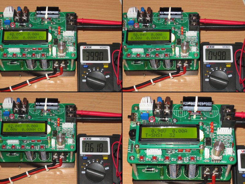
To begin with, the accuracy of the voltage setting and measurement by the converter.
5, 10, 20 and 30 volts were consistently exposed.
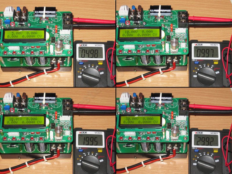
Now respectively 40, 50 and 62 Volts.
Accuracy will not say that it is magnificent, but quite tolerable.
In the end, he noticed that after a while the radiator warmed up to 32 degrees, although there was no heavy load, it seems to be slightly warmed up by a 54 Volt linear regulator on the power board.
Now there are some of the same tests, but in terms of checking the accuracy of the task and measuring the current.
As the load was a multimeter.
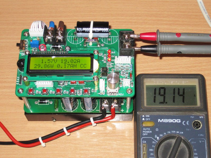
1, 5, 10 and 15 Ampere.
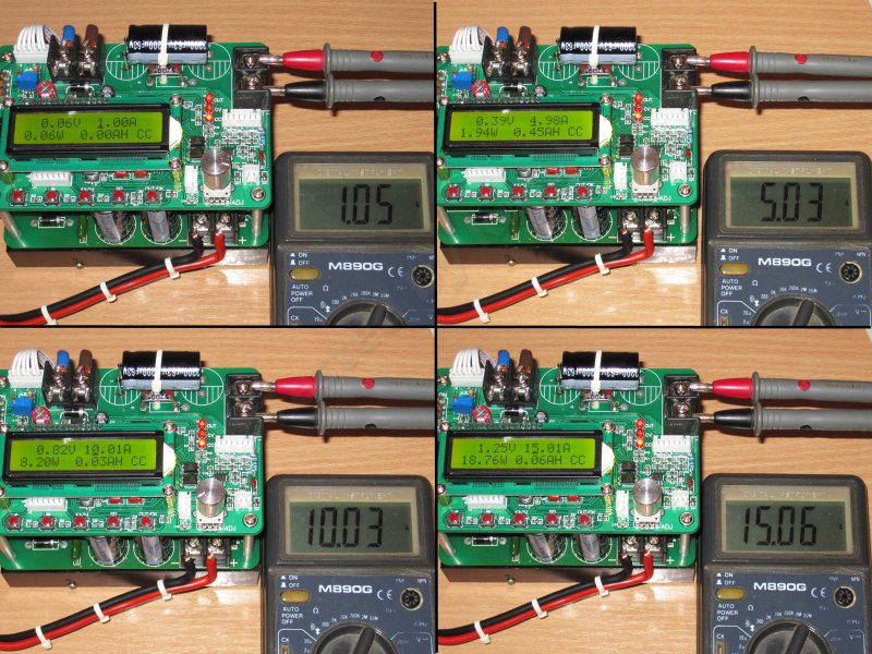
The multimeter has a limit of 20 Amps, so I checked it to 19, and then only for a short time, since the cables to the probes start to get very hot.
It was noticed that the values are somewhat "floating" in the direction of decreasing, I suspect that the multimeter shunt does not feel well from such a current. the total power dissipated on the shunt and probes was about 30 watts.
We proceed to the continuation of the epic assembly of the power supply.
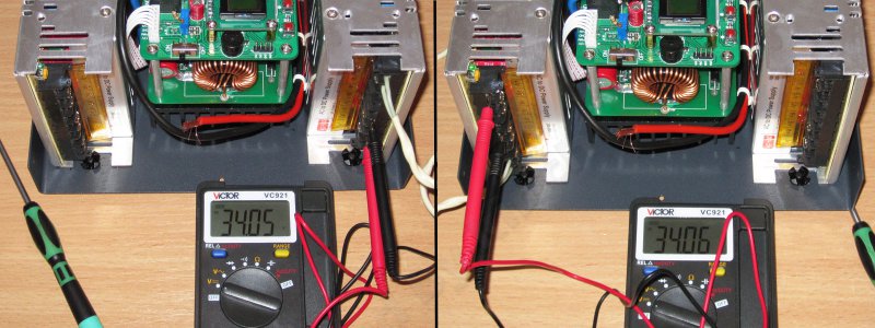
Before connecting power supply units, it is desirable to set an identical voltage at their outputs.
I decided not to use them at regular 36 volts, but to reduce it to 34.
In total, this gives 68 volts, which at maximum 62 is enough.
In general, you can take other power supplies, for example, 48 - 60 or 72 Volts.
Alternatively, use EATON power supplies, they can be sold at auctions taken from the PBX (if not confusing).
Having finished the setting, I connected all the necessary wires and pulled them off with ties, giving a more or less decent appearance. And since there is a fan next to them, it’s better when the wires are organized into harnesses, so there’s less chance of getting into where it’s not necessary.

Very pleased with the panel housing, they have already applied a grid with a pitch of 5mm, it is convenient to use when installing various elements and parts.
I put the fan almost to the bottom, or rather 5 mm from the bottom, but it is better to lift it 5 mm higher, since the wiring harnesses were not very good under it.
By the way, a screw is screwed into the case at the bottom center, but I did not use it in order not to pierce the wires.
In the power supply I used the familiar SUNON 12 volt fan, models with a capacity of 68 m3 / h and a declared noise of 33 dBA.
In general, a fairly high-quality fan cost about two dollars.
Since a black protective cover was purchased for the fan, and the back panel also has a color, I also chose black hardware for fasteners.
Special screws ended, I had to improvise. I took the hardware for the hard drive, and instead of the nuts I used the body stands with the corresponding thread.
Also on the rear panel was installed a 230 volt power connector and a USB connector.
A little bit about the connectors.
1. To connect to a computer, I used the same connector as this one, and the mounting system itself was used exactly the same, I see no reason to repeat the description.
2, 3, 4. To connect the power switch used standard 6.3mm terminals with a latch. For insulation, I took silicone insulators, and since the cable was stripped to a rather large length, after all I restored the protective sheath with the help of transparent heat shrinkage.
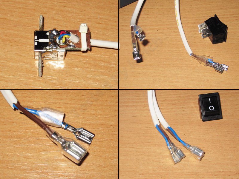
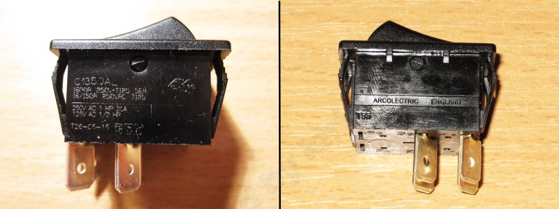
With the power switch was also not so smooth.
Having bought by habit a small power switch familiar to me, I later found out that it is designed for current only up to 3 Amps, and this is clearly not enough for my power.
At the same time, I had to buy a new switch, the seller advised the switch of Arcolectric, as a very high-quality one, still minus one and a half dollars.
But at the same time a third one was bought with a choice. also of high quality, but of the push type, not the keyboard type. Backlit, beautiful, so I got about another half a bucks, I did not quite like it, pretty tight.
Trial inclusion is already in the case. While everything works, well, or pretends that it works :)

Then there should have been a description of the continuation of the assembly process for the power supply, but for some reason during the next save I gave out -
Error: Description must be between 200 and 15000 characters: (
In general, the review had to be divided into two.
I say honestly, I did not set myself the goal of writing a great review and I didn’t expect to see this inscription. I just described the boards and the process of my struggle with the engineering of China, but unexpectedly for me, the review came out very well.
But already at this stage I can print a summary of this product.
There will be no pros and cons, I’ll just write a brief squeeze of my vision of this device.
The fee is quite normal, the price is excellent (at least below the price I have not seen anywhere else).
In addition, the board is fully functional "out of the box", even the USB-RS232 converter was put in the kit, which I did not expect.
I was very pleased with the improved power system, the reliability should increase in comparison with the previous versions.
But of course, it was not done without some of the “shoals”, most likely due to the savings in its production.
Above, I described how the board underwent some modifications, it’s better to do it right away, for example:
Increase the cross-section of the power tracks of the PCB (almost free)
Solder the findings of some elements (here as someone lucky, it may already be normally soldered)
It is advisable to replace the output capacitors from 63 Volts with 80 or 100 Volts. Perhaps these are the only components that are installed completely without stock.
Some improvements are more "cosmetic" in nature, for example:
Replacing all small electrolytic capacitors with better ones.
Installing an additional capacitor on the power board
Adding security elements to prevent damage to the analog part and the processor in case of breakdown of the input PWM stabilizer.
Of the frank flaws, I can only say that the temperature sensor is extremely ill-designed, as it was possible to do so, it is not clear to me.
It is hard for me to say about the output power, since I physically have no opportunity to test the operation of this board at such capacities. But before that, I sometimes met mentions on the Internet that the board was working fine, and the previous power supply was still working.
Although I would not for a long time to load it at full capacity. - the discount is not provided, but the current price of $ 21.73 is in my opinion very good.
The rest of the goods were bought, the stores did not provide any discounts.
This product is provided for writing a review by the store.
Good day to all! Today I want to bring to your attention the Laboratory Power Supply (LBP). I think every novice radio amateur was faced with the problem of obtaining the necessary voltage for one or another of their own homemade, because each device requires a different voltage. I encountered this problem the other day. It was necessary to power a homemade amplifier, and the necessary voltage was not at hand. Well, this is not my first home-made with which I have problems. So I got to work.
And so, we need:
-Korpus (you can buy ready, but how can I take it from a computer power supply)
-Transformer with output voltages up to 30V and current up to 1.5 amperes (I took the trans more powerful because 1.5A is not enough for me)
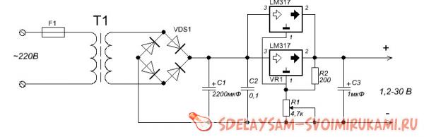
-Simple set of radio components:
- Diode bridge on 3A.
- Electrolytic capacitor 50V 2200 microfarads.
-Condenser ceramic 0.1mkf (to more smooth out the ripple).
- LM317 microchip (in my case there are 2 such microcircuits).
- Resistor variable to 4.7 ohms.
-Resistor 200th 0.5Wat.
-Condenser ceramic for 1mkf.
- Old analog tester (I used as a voltmeter).
-Textolite and iron chlorine (for board etching).
- terminals.
-Wire.
- Soldering accessories.
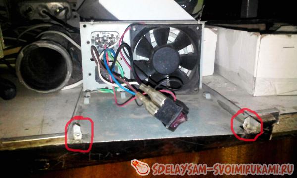
Getting started! The case I took from the computer Power Supply. We disassemble it and pull out the insides and saw off the front panel (the one with which the wires go out) as in the photo.
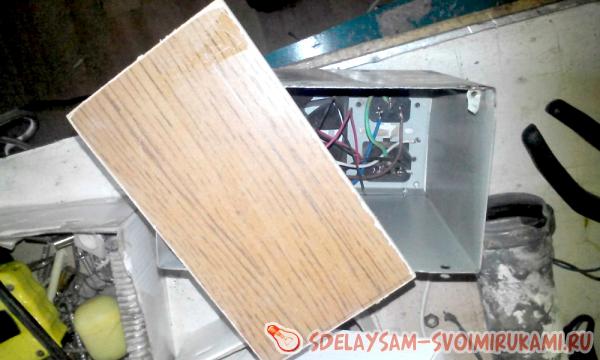
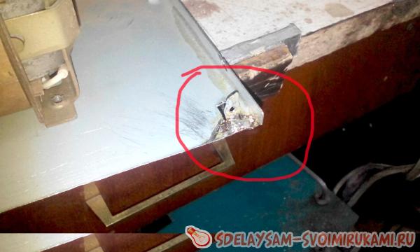
We cut off the board fastenings on one side and bend them in such a way so that later we can fasten the front panel made by us onto them.
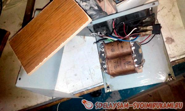
We choose a place for a transformer, drill a hole in the lower part of the body and fix the transformer.
Now let's get down to picking up the board to begin with. We transfer the pre-printed board to textolite.

And throw in chlorine for 10-20 minutes. After we have corroded we drill holes and we charge the board.

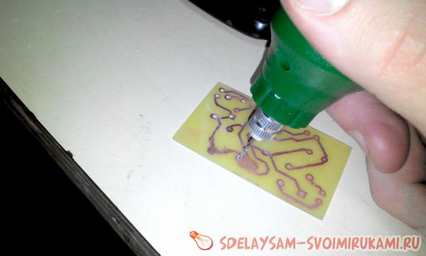
We solder the elements according to the scheme.
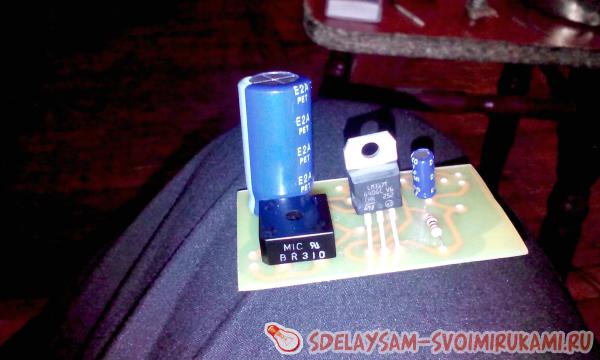

We take the wires, collect the circuit and pack everything into the case. IMPORTANT! (The microcircuit needs to be installed on the radiator, since under heavy loads it gets very hot and can fail). That's what happened.
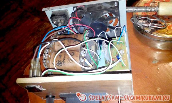
Now you need to get a voltmeter from the old tester. To do this, simply cut off the indicator from the plastic case.