When assembling self-made electronic circuits, one necessarily encounters the selection of necessary capacitors. Moreover, for assembling the device, it is possible to use condensers that have already been in use and have worked for some time in electronic equipment. Naturally, before reuse it is necessary to check the capacitors., especially the capacity of electrolyticwhich are more susceptible to aging.
When selecting capacitors of constant capacity, it is necessary to understand the labeling of these radio elements, otherwise, if an error occurs, the assembled device will either refuse to work correctly or will not work at all.
The capacitor has several important parameters that should be considered when using them.
The first is capacitor capacitance. Measured in fractions of Farada.
The second is admission. Or in another way nominal capacity tolerance from specified. This parameter is rarely taken into account, as radio elements with a tolerance of up to ± 20% and sometimes more are used in household radio equipment. It all depends on the purpose of the device and the specific features of the device. On schematic diagrams this parameter is usually not specified.
The third thing that is indicated in the marking of the capacitor is permissible operating voltage. This is a very important parameter, you should pay attention to it, if the capacitor will be operated in high voltage circuits.
So, let's look at how capacitors of constant capacity are labeled.
Some of the most popular capacitors that can be used are the constant capacitors K73 - 17, K73 - 44, K78 - 2, ceramic KM-5, KM-6 and the like. Also in the electronic equipment of foreign production analogs of these capacitors are used. Their labeling is different from the labeling of domestic manufacturers.
Domestic capacitors K73-17 are polyethylene terephthalate protected capacitors. On the case of these capacitors, marking is applied with an alphanumeric index, for example, 100nJ, 330nK, 220nM, 39nJ, 2n2M.
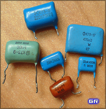
K73 series capacitors and their labeling
Marking rules.
Rated capacitor capacitance.
Capacities from 100 pF to 0.1 μF are labeled in nanofarad, indicating the letter H or n.
Designation 100 n Is the value of the nominal capacitance of the capacitor. For 100n - 100 nanofarad (nF) - 0.1 microfarad (μF). Thus, a capacitor with an index of 100n has a capacitance of 0.1 μF. For other designations similarly. For example:
330n - 0.33 μF, 10n - 0.01 μF. For 2n2, 0.0022 microfarad or 2200 picofarads (2200 pF).
You can find type marking 47 HC. This capacity marking corresponds to the labeling 47 nK and 47 is nanofarad or 0.047 microfarad. Similarly, 22NS - 0.022 microfarad.
In order to easily determine the capacity, it is necessary to know the designations of the main partial units - milli, micro, nano, pico and their numerical values.
Also in the marking capacitors K73 found such designations as M47C, M10C.
Here letter M conditionally means microfarad. The value 47 is after M, that is, the nominal capacitor capacity is a fraction of the microfarad, that is, 0.47 microfarad. For M10C - 0.1 microfarad. It turns out that the capacitance of the capacitor labeled M10С is equal to the capacitance of the capacitor labeled 100nJ. Only conditional marking is slightly different.
Thus, a capacitance of 0.1 μF and above is indicated with the letter M, m instead of a decimal point, an insignificant zero is omitted.
The nominal capacity of domestic capacitors up to 100 pF is designated in picofarad, putting the letter P or p after the number. If the capacity is less than 10 pF, then put the letter R and two numbers. For example, 1R5 = 1.5 pF.
On ceramic capacitors (type KM5, KM6), which have small sizes, usually only the numerical code of capacity is indicated.

Ceramic capacitors with marked capacity marking with a numeric code
For example, numeric marking 224 corresponds to a value of 220,000 picofarads, or 220 nanofarads and 0.22 μF. In this case, 22 is the numerical value of the nominal value. The number 4 indicates the number of zeros. Resulting the number is the capacitance value in picofarad. At 221, the capacity is 220 pF, at 220 - 22 pF. If a four-digit code is used in the capacitor marking, the first three digits are the numerical value of the nominal value, and the last, fourth number is the number of zeros. So at 4722, the capacity is 47200 - 47.2 nF.
The permissible deviation of capacity is marked either by a number in percent (± 5%, 10%, 20%), or by a Latin letter. Sometimes you can find the old designation of the tolerance encoded by the Russian letter. The tolerance of capacitance for a capacitor is similar to the tolerance of resistors.
Letter code of capacitor capacitance deviation (tolerance).
So if the capacitor with the following marking is M47C, then its capacity is 0.047 uF, and the tolerance is ± 10% (according to the old marking with a Russian letter). It is rather difficult to meet a capacitor with a tolerance of ± 0.25% (by marking with a Latin letter) in household equipment, therefore the value with a larger error is chosen. Mostly in household appliances are widely used capacitors with a tolerance H, M, J, K. The letter designating the tolerance is indicated after the value of the nominal capacitance of the capacitor, like this 22n K, 220n M, 470n J.
Table for decoding the conventional letter code for the tolerance of capacitance of capacitors.
| D% down | Bukvennoe designation | |
| lat | rus | |
| ± 0.05p | A | |
| ± 0.1p | B | F |
| ± 0,25p | C | Have |
| ± 0.5p | D | D |
| ± 1.0 | F | R |
| ± 2.0 | G | L |
| ± 2.5 | H | |
| ± 5.0 | J | AND |
| ± 10 | K | WITH |
| ± 15 | L | |
| ± 20 | M | AT |
| ± 30 | N | F |
| -0...+100 | P | |
| -10...+30 | Q | |
| ± 22 | S | |
| -0...+50 | T | |
| -0...+75 | U | Uh |
| -10...+100 | W | YU |
| -20...+5 | Y | B |
| -20...+80 | Z | BUT |
The permissible operating voltage of the capacitor.
An important parameter of the capacitor is also the permissible operating voltage. It should be taken into account when assembling home-made electronics and repairing household radio equipment. For example, when repairing compact fluorescent lamps It is necessary to select a capacitor for the appropriate voltage when replacing failed capacitors. It would not be superfluous to take a capacitor with an operating voltage margin.
Usually, the value of the permissible operating voltage of the capacitor is indicated after the nominal capacity and tolerance. It is indicated in volts with the letter B (old marking), and V (new marking). For example, like this: 250V, 400V, 1600V, 200V. In some cases, the letter V is omitted.
Sometimes a Latin encoding is used. To decrypt, use the table of alphabetic coding of the operating voltage of the capacitors.
| Hoperating voltageA b | Bkey code |
| 1,0 | I |
| 1,6 | R |
| 2,5 | M |
| 3,2 | A |
| 4,0 | C |
| 6,3 | B |
| 10 | D |
| 16 | E |
| 20 | F |
| 25 | G |
| 32 | H |
| 40 | S |
| 50 | J |
| 63 | K |
| 80 | L |
| 100 | N |
| 125 | P |
| 160 | Q |
| 200 | Z |
| 250 | W |
| 315 | X |
| 350 | T |
| 400 | Y |
| 450 | U |
| 500 | V |
These are the most important parameters of capacitors that you should know when selecting the right capacitor. Marking imported capacitors different, but in many ways consistent with the above.
Length and distance Weight Measures volume of bulk food and food products Area Volume and units of measure in culinary recipes Temperature Pressure, mechanical stress, Young's modulus Energy and work Power Strength Time Linear velocity Flat angle Thermal efficiency and fuel efficiency Numbers Units of measurement of information Information Exchange rates Sizes women's clothing and shoes Men's clothing and shoes dimensions Angular velocity and rotational speed Acceleration Angular acceleration Density Specific volume Moment of inertia Momen tons of force Torque Specific heat of combustion (by mass) Energy density and specific heat of combustion of fuel (by volume) Temperature difference Thermal expansion coefficient Thermal resistance Specific thermal conductivity Specific heat capacity Energy exposure, thermal radiation power Heat flux density Heat transfer coefficient Volume flow Mass flow Molar flow Mass flux density Molar concentration Mass concentration in solution Dynamic (absolute) viscosity Kinematic viscosity Surface tension Vapor permeability Vapor permeability, vapor transfer rate Sound level Microphone sensitivity Sound pressure level (SPL) Brightness Luminous intensity Illuminance Resolution in computer graphics Frequency and wavelength Optical power in diopters and focal length Optical power in diopters and lens increase (×) charge Linear charge density Surface charge density Bulk charge density Electric current Linear current density Surface current density Tension electric field Electrostatic potential and voltage Electrical resistance Specific electrical resistance Electrical Conductivity Electrical Conductivity Electrical Capacity Inductance American Wire Gauge Levels in dBm (dBm or dBm), dBV (dBV), Watts, and Other Units Magnetic Motive Force Tension magnetic field Magnetic flux Magnetic induction Absorbed dose rate of ionizing radiation Radioactivity. Radioactive decay Radiation. Exposure dose Radiation. Absorbed dose Decimal prefixes Data transfer Typography and image processing Units of timber volume calculation Molar mass calculation Periodic system of chemical elements DI Mendeleeva
1 nanofarad [nF] = 0.001 microfarad [μF]
Baseline
Converted value
farad exafarad petafarad terafarad gigafarad megafarad kilo farad hectofarad decafarad decifarad centipharad millifarad microfarad nanofarad picofarad femto farad atto farad pendant per volt abfarad cfmd mdfd mdfdmd mfmd mfmad mfarad microfarad nimfarad picofarad femtofarad atto farad pendant per volt
Read more about electrical capacitance
General information
Capacitance is a quantity that characterizes the ability of a conductor to accumulate a charge equal to the ratio of electric charge to potential difference between conductors:
C = Q / ∆φ
Here Q - electric chargemeasured in pendants (CL) - potential difference, measured in volts (V).
In the SI system, the electric intensity is measured in farads (F). This unit is named after the English physicist Michael Faraday.
Farad is a very large capacity for insulated conductor. Thus, a solitary metal ball with a radius of 13 solar radii would have a capacity equal to 1 farad. And the capacity of a metal ball the size of Earth would be about 710 microfarads (uF).
Since 1 farad is a very large capacitance, therefore smaller values are used, such as: microfarad (uF), equal to one millionth farad; nanofarad (nF), equal to one billionth; picofarad (pf), equal to one trillionth farad.
In the CGSE system, the main unit of capacity is centimeter (cm). 1 centimeter capacity is the electrical capacity of the ball with a radius of 1 centimeter, placed in a vacuum. CGSE is an advanced CGS system for electrodynamics, that is, a system of units in which centimeter, gram, and second are taken as basic units for calculating length, mass, and time, respectively. In extended GHS, including CGSE, some physical constants are taken as a unit to simplify formulas and facilitate calculations.
Capacity utilization
Capacitors - devices for accumulating charge in electronic equipment
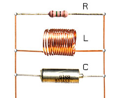
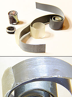
The concept of electrical capacitance refers not only to the conductor, but also to the capacitor. A capacitor is a system of two conductors separated by a dielectric or vacuum. In the simplest embodiment, the design of the capacitor consists of two electrodes in the form of plates (plates). A capacitor (from an armor. Condensare - “condense”, “thicken”) is a two-electrode device for accumulating charge and energy of an electromagnetic field, in the simplest case it consists of two conductors separated by some kind of insulator. For example, sometimes radio amateurs, in the absence of finished parts, make trimming capacitors for their circuits from varnished wires of different diameters, while the thinner wire is wound onto a thicker one. By adjusting the number of turns, radio amateurs fine tune the equipment circuit to the desired frequency. Examples of image capacitors on electrical circuits are shown in the figure.
History reference
Only 275 years ago, the principles of creating capacitors were known. Thus, in 1745, German physicist Ewald Jürgen von Kleist and Dutch physicist Peter van Muschenbruck created the first capacitor, the “Leyden jar”, in Leiden, where the walls of a glass jar were dielectric, and the plates of the experimenter holding the vessel served as plates. Such a “bank” made it possible to accumulate a charge of the order of a micro-pendant (μC). After it was invented, experiments and public performances were often conducted with it. To do this, the bank was first charged with static electricity, rubbing it. After that, one of the participants touched the can with his hand, and received a small electric shock. It is known that 700 Parisian monks, holding hands, conducted a Leiden experiment. At that moment, when the first monk touched the head of the jar, all 700 monks, confined in one convulsion, cried out in horror.
The “Leyden Bank” came to Russia thanks to the Russian Tsar Peter I, who met Mushenbruck during his travels in Europe, and learned more about the experiments with the “Leyden Bank”. Peter I established the Academy of Sciences in Russia, and ordered various devices for the Academy of Sciences to Mushenbruck.
In the future, the capacitors improved and became smaller, and their capacity - more. Capacitors are widely used in electronics. For example, a capacitor and an inductor form an oscillating circuit, which can be used to tune the receiver to the desired frequency.
There are several types of capacitors differing in constant or variable capacitance and dielectric material.
Capacitor examples
The industry produces a large number of types of capacitors for various purposes, but their main characteristics are capacity and operating voltage.
Typical values containers Capacitors vary from picofarad units to hundreds of microfarads, with the exception of ionistors, which have a slightly different nature of capacity formation - due to the double layer at the electrodes - in this they are similar to electrochemical batteries. Nanotube-based supercapacitors have an extremely developed electrode surface. For these types of capacitors, typical capacitance values are dozens of farads, and in some cases they are able to replace conventional electrochemical batteries as current sources.
The second most important capacitor parameter is its operating voltage. Exceeding this parameter can lead to capacitor failure, therefore, when building real circuits, it is common to use capacitors with twice the value of the operating voltage.
To increase the values of capacitance or operating voltage, use the method of combining capacitors into batteries. With serial connection two capacitors of the same type, the working voltage is doubled, and the total capacitance is halved. With parallel connection two capacitors of the same type, the working voltage remains the same, and the total capacity is doubled.
The third most important capacitor parameter is temperature coefficient of change of capacity (TKE). It gives an idea of the change in capacity in a changing temperature.
Depending on the purpose of use, capacitors are divided into general-purpose capacitors, the requirements for which parameters are noncritical, and special-purpose capacitors (high-voltage, precision, and with various TKE).
Capacitor marking
Like resistors, depending on the dimensions of the product, a full label can be used indicating the nominal capacity, deviation class and operating voltage. For small versions of capacitors used code marking of three or four numbers, mixed alphanumeric marking and color marking.
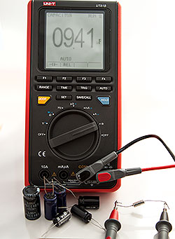
Corresponding tables of recalculation of markings at nominal, operating voltage and TKE can be found on the Internet, but the most effective and practical method for checking the nominal and operability of an element of a real circuit remains the direct measurement of the parameters of a soldered capacitor using a multimeter.
A warning: since capacitors can accumulate a large charge at very high voltagein order to avoid defeat electric shock It is necessary to discharge the capacitor before measuring the parameters of the capacitor, shorting its terminals with a wire with high resistance to external insulation. It is best suited for this standard wire measuring device.
Oxide capacitors: This type of capacitor has a large specific capacity, that is, a capacity per unit weight of the capacitor. One plate of such capacitors is usually an aluminum strip coated with a layer of aluminum oxide. The second plate is electrolyte. Since the oxide capacitors have polarity, it is of fundamental importance to include such a capacitor in the circuit strictly in accordance with the polarity of the voltage.
Solid Capacitors: instead of the traditional electrolyte, they use organic current-carrying polymer or semiconductor as the lining.
Variable capacitors: capacitance can be changed mechanically, by electrical voltage or by temperature.
Film Capacitors: The capacitance range of this type of capacitor is from about 5 pF to 100 μF.
There are other types of capacitors.
Ionistors
Nowadays, ionistors are gaining popularity. An ionistor (supercapacitor) is a hybrid of a capacitor and a chemical current source whose charge accumulates at the interface between two media, the electrode and the electrolyte. The beginning of the creation of ionistors was laid in 1957, when a capacitor with a double electric layer on porous carbon electrodes was patented. The double layer as well as the porous material helped to increase the capacity of such a capacitor by increasing the surface area. In the future, this technology was supplemented and improved. Ionistors entered the market in the early eighties of the last century.
With the advent of ionistors, it became possible to use them in electrical circuits as voltage sources. Such supercapacitors have a long service life, low weight, high charge-discharge rates. In the future, this type of capacitor can replace conventional batteries. The main disadvantages of ionistors are their specific energy, which is lower than that of electrochemical batteries, (low energy per unit weight), low operating voltage, and significant self-discharge.
Ionistors are used in Formula 1 cars. In energy recovery systems, during deceleration, electrical energy is generated, which is stored in a flywheel, batteries, or ionistors for further use.
In consumer electronics, ionistors are used to stabilize the main power supply and as a backup power source for devices such as players, flashlights, automatic utility meters and other devices with battery power and varying loads, providing power during an increased load.
In public transport, the use of ionistor is particularly promising for trolley buses, since it becomes possible to realize an autonomous course and increase maneuverability; also ionistors are used in some buses and electric vehicles.
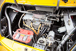
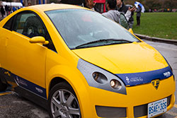
Electric cars are currently produced by many companies, for example: General Motors, Nissan, Tesla Motors, Toronto Electric. The University of Toronto, in partnership with Toronto Electric, developed the fully Canadian A2B electric vehicle. It uses ionistors along with chemical power sources, the so-called hybrid electrical energy storage. The engines of this car are powered by batteries weighing 380 kilograms. Also for recharging using solar panels installed on the roof of the electric vehicle.
Capacitive touch screens
In modern devices, touch screens are increasingly used, which allow you to control devices by touching panels with indicators or screens. Touch screens come in different types: resistive, capacitive, and others. They can respond to one or more simultaneous touches. The principle of operation of capacitive screens is based on the fact that the object of large capacity conducts alternating current. In this case, the subject is the human body.
Surface Capacities
Thus, the surface-capacitive touch screen is a glass panel coated with a transparent resistive material. As a resistive material is usually used with high transparency and low surface resistance of the alloy of indium oxide and tin oxide. Electrodes applying to the conductive layer is small aC voltage, are located at the corners of the screen. When you touch this screen with your finger, a leakage current appears, which is recorded at the four corners by the sensors and transmitted to the controller, which determines the coordinates of the touch point.
The advantage of such screens lies in durability (about 6.5 years of pressing with an interval of one second or about 200 million clicks). They have high transparency (about 90%). Due to these advantages, capacitive screens since the year 2009 have actively begun to displace resistive screens.
The lack of capacitive screens is that they do not work well at low temperatures, there are difficulties with the use of such screens in gloves. If the conductive coating is located on the outer surface, then the screen is quite vulnerable, so capacitive screens are used only in those devices that are protected from the weather.
Projection Capacitive Screens
In addition to the surface-capacitive screens, there are projection-capacitive screens. Their difference lies in the fact that a grid of electrodes is applied on the inside of the screen. The electrode to which they touch, together with the human body forms a capacitor. Thanks to the grid, you can get the exact coordinates of the touch. The projection capacitive screen responds to the touch in thin gloves.
Projection-capacitive screens also have high transparency (about 90%). They are durable and strong enough, therefore they are widely used not only in personal electronics, but also in automatic devices, including those installed on the street.
Do you have difficulty in converting units of measurement from one language to another? Colleagues are ready to help you. Post your question to TCTerms and within a few minutes you will get the answer.
The simplest consists of two metal plates (plates), separated by a thin layer of dielectric (insulator), which can serve as air, porcelain, mica, ceramics, paper or other material with sufficiently high resistance.Electrical unit capacitor capacitance is a farad (f) - a tribute to the great English scientist Michael Faraday.
In electronics, capacitors are used whose capacity is fractional units of farad: picofarad (pF), nanofarad (nF), microfarad (microfarad).
1 F (farad) = 1000000 uF (microfarad)
1 μF (microfarad) = 1000 nF (nanofarad) = 1000000 pF (picofarad)
1 nF (nanofarad) = 1000 pF (picofarad)
 Ceramic capacitors |
The most common are ceramic capacitors. The capacity of ceramic capacitors is one - thousands of picofarads.
Have the largest capacity electrolytic capacitors, in which the thinnest oxide layer obtained by the electrolytic method is used as an insulator. The capacity of electrolytic capacitors can reach thousands of microfarads. Electrolytic capacitors are usually polar, that is, they have positive and negative poles. Violation of the correct polarity when the electrolytic capacitor is switched on in the circuit is unacceptable, as it can damage it.
On the case of capacitors, along with the value of their capacitance and the value of its possible deviation from the nominal, the value of the working electrical voltage. The capacitors mainly indicate the rated operating voltage at constant current. The inclusion of a capacitor in the circuit, the voltage in which exceeds its operating voltage, is not allowed, since the insulator is destroyed, as a result of which the capacitor fails.
Capacitors, the capacity of which can be changed at specified intervals, are called variable capacitors and trimmers.
For fixed capacitors on the circuit next to the conditional graphic designation indicate the value of capacity. When the capacitance is less than 0.01 μF (10,000 pF), the number of picofarads without a dimension is set, for example, 15, 220, 9100. For a capacity of 0.01 μF and more, the number of microfarads is set.
In electrolytic capacitors near one of the plates put a plus. The same sign usually stands on the case of the capacitor near the corresponding output. Also most often indicate the rated voltage.
For variable capacitors and trimmers indicate the limits of capacitance changes at the extreme positions of the rotor, for example, 6 ... 30, 10 ... 180, 6 ... 470.
Capacitor marking
When marking the denomination on foreign ceramic capacitors, a special encoding is often used, in which last digit in the number indicates the number of zeros (capacity in picofarads). For example:
Capacitor charge
Consider the process of accumulating capacitor electric power. Connect the capacitor plates to the poles of the current source. At the moment of the circuit closure on the capacitor plates will begin to accumulate charge. As soon as the voltage on the capacitor is equalized with the source voltage, the process capacitor charge will end and the current in the circuit will become zero. Thus, at the end of the charge, the DC circuit will be open. If we now slightly increase the voltage of the source, the capacitor will accumulate some more charge. The greater the capacitance of the capacitor, the greater the charge will be on its plates for a given voltage value between the plates.
If the circuit of the capacitor and the DC source is broken, the capacitor remains charged. A charged capacitor can be used as a source of energy, which is stored in it in the form of the electric field energy of the charges on the plates. This is how a capacitor is used in BEAM-robots solar engines. The source of electricity in this case is the solar battery.
Let's see what happens if we now connect a charged capacitor, for example, to an LED (taking into account the polarities). In the resulting circuit current flows again (the discharge current of the capacitor). This current has a direction opposite to the charge current, that is, it flows out of the positively charged capacitor plate as the positive pole of the source. As the discharge voltage on the capacitor decreases, and the current in the circuit begins to decrease. At the moment of discharge termination, the energy of the capacitor will be completely consumed, and the current in the circuit will disappear.
1. Marking in three numbers.
In this case, the first two digits define the mantissa, and the last - the exponent on the base 10, to obtain the nominal in picofarad. The last digit "9" denotes the exponent "-1". If the first digit is “0”, then the capacitance is less than 1 pF (010 = 1.0 pF).
| code | picofarads, pF, pF | nanofarad, nF, nF | microfarads, μF, μF |
| 109 | 1.0 pF | ||
| 159 | 1.5 pF | ||
| 229 | 2.2 pF | ||
| 339 | 3.3 pF | ||
| 479 | 4.7 pF | ||
| 689 | 6.8 pF | ||
| 100 | 10 pF | 0.01 nF | |
| 150 | 15 pF | 0.015 nF | |
| 220 | 22 pF | 0.022 nF | |
| 330 | 33 pF | 0.033 nF | |
| 470 | 47 pF | 0.047 nF | |
| 680 | 68 pF | 0.068 nF | |
| 101 | 100 pF | 0.1 nF | |
| 151 | 150 pF | 0.15 nF | |
| 221 | 220 pF | 0.22 nF | |
| 331 | 330 pF | 0.33 nF | |
| 471 | 470 pF | 0.47 nF | |
| 681 | 680 pF | 0.68 nF | |
| 102 | 1000 pF | 1 nF | |
| 152 | 1500 pF | 1.5 nF | |
| 222 | 2200 pF | 2.2 nF | |
| 332 | 3300 pF | 3.3 nF | |
| 472 | 4700 pF | 4.7 nF | |
| 682 | 6800 pF | 6.8 nF | |
| 103 | 10,000 pF | 10 nF | 0.01 uF |
| 153 | 15000 pF | 15 nF | 0.015 uF |
| 223 | 22000 pF | 22 nF | 0.022 uF |
| 333 | 33,000 pF | 33 nF | 0.033 microfarad |
| 473 | 47000 pF | 47 nF | 0.047 uF |
| 683 | 68000 pF | 68 nF | 0.068 uF |
| 104 | 100,000 pF | 100 nF | 0.1 uF |
| 154 | 150000 pF | 150 nF | 0.15 microfarad |
| 224 | 220000 pF | 220 nF | 0.22 microfarad |
| 334 | 330000 pF | 330 nF | 0.33 uF |
| 474 | 470000 pF | 470 nF | 0.47 uF |
| 684 | 680000 pF | 680 nF | 0.68 uF |
| 105 | 1,000,000 pF | 1000 nF | 1 uF |
2. Four-digit marking.
This marking is similar to that described above, but in this case, the first three digits define the mantissa, and the last indicates the exponent on the base 10, to obtain the capacity in picofarad. For example:
1622 = 162 * 10 2 pF = 16200 pF = 16.2 nF.
3. Alphanumeric marking.
With this marking, the letter indicates the decimal point and the designation (μF, nF, pF), and the numbers indicate the value of the capacitance:
15p = 15 pF, 22p = 22 pF, 2n2 = 2.2 nF, 4n7 = 4.7 nF, μ33 = 0.33 μF
It is often difficult to distinguish the Russian letter "p" from the English "n".
Sometimes the letter R is used to denote the decimal point. Usually, these are labeled containers in microfarads, but if there is a zero in front of the letter R, then these are picofarades, for example:
0R5 = 0.5 pF, R47 = 0.47 μF, 6R8 = 6.8 μF
4. Planar Ceramic Capacitors.
Ceramic SMD capacitors are usually or not labeled at all except for the color (I do not know the color marking, if someone tells you - I will be glad, I know only that the lighter the smaller the capacity) or are marked with one or two letters and a number. The first letter, if it indicates the manufacturer, the second letter indicates the mantissa in accordance with the table below, the figure is the exponent on the base 10, to get the capacity in picofarad. Example:
N1 / according to the table we define the mantissa: N = 3.3 / = 3.3 * 10 1 pF = 33 pF
S3 / according to the table S = 4.7 / = 4.7 * 10 3 pF = 4700 pF = 4.7 nF
| marking | value | marking | value | marking | value | marking | value |
| A | 1.0 | J | 2.2 | S | 4.7 | a | 2.5 |
| B | 1.1 | K | 2.4 | T | 5.1 | b | 3.5 |
| C | 1.2 | L | 2.7 | U | 5.6 | d | 4.0 |
| D | 1.3 | M | 3.0 | V | 6.2 | e | 4.5 |
| E | 1.5 | N | 3.3 | W | 6.8 | f | 5.0 |
| F | 1.6 | P | 3.6 | X | 7.5 | m | 6.0 |
| G | 1.8 | Q | 3.9 | Y | 8.2 | n | 7.0 |
| H | 2.0 | R | 4.3 | Z | 9.1 | t | 8.0 |
5. Planar Electrolytic Capacitors.
Electrolytic SMD capacitors are labeled in two ways:
1) Capacity in microfarads and operating voltage, for example: 10 6.3V = 10µF at 6.3V.
2) A letter and three digits, with the letter indicating the operating voltage in accordance with the table below, the first two digits determine the mantissa, the last digit is the exponent on the base 10, to obtain the capacity in picofarad. A strip on such capacitors indicates a positive lead. Example:
According to the table "A" - the voltage is 10V, 105 is 10 * 10 5 pF = 1 μF, i.e. This is a capacitor of 1 microfarad at 10V
| letter | e | G | J |
The condenser can be compared with a small battery, it can quickly accumulate and just as quickly give it away. The main parameter of a capacitor is its capacity (C). An important property of a capacitor is that it provides resistance to alternating current, the greater the frequency alternating currentthe less resistance. D.C the capacitor does not pass.
As well, capacitors are of fixed capacitance and variable capacitance. Capacitors are used in oscillating circuits, various filters, for separating DC and AC circuits, and as interlocking elements.

The basic unit of measure for capacitance is farad (f) - this is a very large value, which is not applied in practice. In electronics, capacitors with a capacity of picofarad (pf) to tens of thousands microfarad (uF). 1 μF is one millionth of a farad, and 1 pF is one millionth of a microfarad.
On electrical concepts, a capacitor is displayed as two parallel lines symbolizing its main parts: two plates and a dielectric between them. Near the designation of a capacitor usually indicate its nominal capacity, and sometimes its nominal voltage.
Rated voltage - the voltage value indicated on the capacitor case, at which normal operation is guaranteed for the entire lifetime of the capacitor. If the voltage in the circuit exceeds the rated voltage of the capacitor, it will quickly fail, and may even explode. It is recommended to put capacitors with a voltage margin, for example: in a 9-volt circuit, you must install a capacitor with a nominal voltage of 16 volts or more.
Temperature coefficient of capacitor capacitance (TKE)
TKE shows the relative change in capacitance when the temperature changes by one degree. TKE can be positive and negative. According to the value and the sign of this parameter, the capacitors are divided into groups, which are assigned corresponding letters on the case.
Capacitor marking
Capacity from 0 to 9999 pF can be specified without the unit of measurement:
22 = 22p = 22P = 22pF
If the capacitance is less than 10 pF, then the designation may be as follows:
1R5 = 1P5 = 1.5pF
Also capacitors are labeled in nanofarad (nf), 1 nanofarad is equal to 1000 pF and microfarads (uF):
10n = 10H = 10nF = 0.01µF = 10000pF
H18 = 0.18nF = 180pF
1n0 = 1Н0 = 1nF = 1000pF
330N = 330n = M33 = m33 = 330nF = 0.33µF = 330000pF
100H = 100n = M10 = m10 = 100nF = 0.1µF = 100000 pF
1H5 = 1n5 = 1.5nF = 1500pF
4n7 = 4Н7 = 0.0047 μF = 4700 pF
6M8 = 6.8 μF
Digital capacitor marking
If the code is three-digit, then the first two digits indicate the value, the third - the number of zeros, the result in picofarad.
For example: code 104, we assign four zeros to the first two digits, we get 100000pF = 100nF = 0.1 μF.
If the code is four-digit, the first three digits indicate the value, the fourth - the number of zeros, the result is also in picofarad.
4722 = 47200pF = 47,2nF
Electrolytic capacitors
To work in the range sound frequenciesAs well as for filtering rectified supply voltages, large capacitors are necessary. Such capacitors are called electrolytic. Unlike other types of electrolytic capacitors are polar, this means that they can be included only in DC or pulsed voltage circuits and only in the polarity indicated on the capacitor case. Failure to comply with this condition leads to the failure of the capacitor, which is often accompanied by an explosion.