I consider it necessary to express my opinion about the dubious advice in various sources about the "methods of resonant testing of transformers" using the AF generator. The resonant frequency of the transformer depends on the number of turns, the diameter of the wire, the properties of the core material, the height of the gap. Many years ago, the method of shorting part of the coil turns, magnetic antenna (similarly in a transformer), resonance shifted higher in frequency without much damage to the work in the "resonance". Therefore, the locking circuit does not affect the absence of resonance, but only increases its frequency, reducing the quality factor. The shape of a sinusoid with shorted windings is not distorted, and it is generally not reasonable to use pulses because of the occurrence of shock excitation pulses.
The shape of the pulse can be affected by saturation of the core. But then what kind of resonance is it and how much power should a generator be? For several reasons, several resonances may be observed. So one can only regret the wasted time realizing such advice.
Transformers of pulse power supply units fail, most often due to the heating of the primary winding, when a short circuit (short circuit) occurs in the power switches. This especially happens in small-sized transformers, and transformers wound with a thin wire, for example in the power supply units of modern video recorders and video players. The wire heats up in a short time, and the insulation is destroyed. As a result, interturn closures arise, drastically reducing the Q-factor, which violates the operation mode of the oscillator.
In circuits with external excitation, various protections are triggered, including over current, blocking the operation of a switching power supply (SMPS), protecting chips and power switches. When analyzing the fault, it should be assumed that the increased voltage on the secondary and work in the "spacing" is an indicator of the normal quality of the transformer.
One of the most difficult defects is “flickering short-circuit”, that is, manifesting periodically. This is due to electromechanical phenomena, in particular, the chafing of the windings of the windings that are poorly tensioned or not fixed according to the requirements of the winding technology. Uneven heating of different windings and their expansion, taking into account vibrations in a magnetic field, creates conditions for local destruction of the insulation and the occurrence of "flickering" interturn circuits. Then the power keys fail suddenly and, as it were, for no reason.
Such problems generally require special diagnostic methods using the active mode of the transformer. A large number of variants of devices for checking for short-circuit windings do not solve the problem, and in the practice of repair they did not take root due to the low reliability of the results of the checks. The available method of quality control of transformers, in "home" conditions. To do this, use the connection of the low-voltage winding of the transformer pulsed power supply (PSU), or the filament winding of the TDKS to the glow terminals of a working television, approximately as shown in the figures. In this case, the TV is used as a generator of powerful pulses. The presence of short turns is easily determined by the overloading of the source of pulses. But it is more practical to use for this purpose the author's generator, based on the standard SMPS. You can read about one of the variants of such a device.
Fig.1 Option for heat
Fig.2 Option for BP
It is more convenient to use a working SMPS for testing TDX, using it as a pulse generator. TDKS are soldered and switched on according to the test scheme, as a high-voltage converter for receiving an accelerating voltage. Figure 2. The high-voltage output of the TDKS must be connected to the negative output of the multiplier through a simple spark gap. A wire with two crocodile clips can be used. The pulses generated by the SMPS imitate the operation of the TDKS in the operating mode. Pulsed power from the winding of the SMPS ensures the operation of the multiplier and at its terminals + / - a high voltage of 10 - 18 kV arises. This voltage pierces the discharge gap and is observed in the form of a spark. For normally working and healthy TDKS, the spark in the discharge gap reaches 2-4 cm. Thus, it is possible to safely detect the breakdown places of the insulation of the TDX housing of the so-called "fistula".
Despite the high voltage currents are safe, but the application of standard safety requirements does not hurt.
Additional useful information on repairing TVs can be obtained from the section of our Forum: TV repair and Encyclopedia repair. Transformers of various brands, offer online store Dalincom.
This article answers the questions: how to check a pulse transformer and how to check tdks .
Method number 1
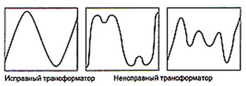
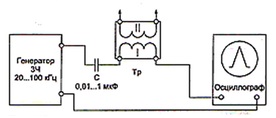
To test the performance transformer You will need an oscilloscope and a sound generator with a frequency range from 20 kHz to 100 kHz. A sinusoidal pulse with an amplitude of 5–10 V is fed to the primary winding of the tested transducer through a capacitor with a capacitance of 0.1–1 μF. The signal of the secondary winding is measured by an oscilloscope connected to it. If the sinusoidal signal is not distorted, in any part of the frequency range, then the transformer being tested is in good condition. Distorted sinusoid indicates a transducer fault. Figure 1 schematically shows the connection method. In Figure 2 - the form of sinusoidal signals.
Fig. 1. Connection diagram of the tested transformer (method number 1)
Fig. 2. The shape of sinusoidal signals (method number 1)
Method number 2
To check the serviceability of the pulse transformer According to this method, you first need to connect a capacitor with a capacity of 0.01-1 μF to the primary winding in parallel and, using an audio frequency generator, apply a signal with an amplitude of 5-10 V to the winding. and, with an oscilloscope, monitor the amplitude of the pulse. If the secondary winding is closed in a working converter, the oscillations in the circuit will stop. From which it can be concluded that due to a short circuit in the coils the resonance in the oscillating circuit is disturbed. Therefore, if there are short-circuited turns in the transformer under test, regardless of the signal frequency, there will be no resonance. Connection diagram of all elements is shown in Figure 3.
Fig. 3. Connection diagram of the tested transformer (method №2)

Method number 3
This method transformer check the same as the previous one, but with a slight difference: the connection of the capacitor is not parallel, but serial. If there are short-circuited coils in the transformer winding, at a resonant frequency, oscillation in the circuit occurs and in the future it will be impossible to cause a resonance.
Connection method is shown schematically in Figure 4.
Fig. 4. Connection diagram of the tested transformer (method №3)
Method number 4
The three previous methods are better suited for testing an isolation transformer and a power transformer, and check the efficiency of the converter TDKS using these methods is possible only approximately. Assess the suitability of a line transformer as follows.
A rectangular frequency pulse of 1-10 kHz with a small amplitude needs to be sent along the collector winding of the converter under test (an output signal for calibrating the oscilloscope is suitable). At the same place you want to connect the input of the oscilloscope and, based on the resulting image, you can draw conclusions. If a TDSK OK, the amplitude of the observed differentiated signals will be about the same as the original square wave pulses. If there are short-circuited turns in the transformer, short differentiated signals with an amplitude lower by several times than the original rectangular pulse will be visible in the picture.
This verification method is considered rational, since only one measuring device is needed for testing the TDX. But you should also take into account that not all oscilloscopes are equipped with a generator output, which is used to calibrate the instrument. For example, quite common oscilloscopes C1-94 and C1-112 are not equipped with a separate calibration generator. To solve this problem, you can independently assemble a simple generator that can fit on a single chip. In addition, it is not difficult to install it in an oscilloscope housing, which will provide a quick and effective verification of the TDX transformers. The generator assembly diagram is shown in Figure 5.
Fig. 5. Scheme of the generator (method number 4)

The assembled generator is installed inside the oscilloscope in any suitable place, power is supplied from 12 V tires. As a switch, it is more convenient to use a dual-type toggle switch (P2T1-1B), which is better placed on the front of the device, next to the input connector of the oscilloscope.
Power is supplied to the generator through one pair of contacts, through another pair of contacts the input of the oscilloscope itself is connected to the output of the generator. Due to this, in order to check the serviceability of the transformer, it is enough to connect the converter winding and the oscilloscope input with a simple signal wire.
Method number 5
This method describes testing of TDKS for inter-turn short circuits and breaks in the windings without using a generator. Before testing the converter, disconnect its output from the power supply (110-160 V). Further, with the help of a special jumper, it is necessary to close the collector of the horizontal output transistor with a common wire. After that, the power supply unit on the 110-160 V circuit needs to be loaded with a 40-60 W, 220 V. light bulb. Now you should find a voltage of 10-30 V on the secondary windings of the power supply converter and pass it through a transistor, with a resistance of 10 Ohm, to the disconnected output TDX. The signal of the resistor is controlled by an oscilloscope. If the transformer under test has inter-turn closures, then the image will look like a “dirty-fluffy rectangle”, and the main part of the voltage will drop on the resistor. If there are no closures, the rectangle pattern will be clean, and the drop of the electrical signal on the resistor will be no more than a few volts.
By monitoring the signals on the secondary windings, you can find out if the transformer is working or not. If the picture shows a rectangle, then the winding is whole, if there is no rectangle, the winding is broken. Next you need to remove the resistance resistor (10 ohms) and hang on all secondary windings TDKS load of 0.2-1.0 kΩ. If the output image is the same as at the input, then the TDKS transformer is operational.
Who didn’t have it, change the burnt line transistor ,
the TV turns on, the raster is normal after a minute
line transistor, and do not have time to measure.
Failure horizontal transistor probably the most common problem in TVs. Horizontal scanning is the main load for the power supply and is essentially an additional power supply unit from which voltage is removed for vertical scanning, video amplifiers, etc. It’s good when repairs end with replacing the horizontal transistor, but sometimes the horizontal transistor after the replacement, immediately or a little later, fails again.
And so if, after replacing the line transistor, immediately or after some time, it fails again, you need to pay attention to the following:
- Is not the overvoltage of the line feed power supply HOT.
- Whether the transistor is heated before the failure or not. If the transistor heats up, it means that the load on it is more than expected. In this case, faulty, there may be both a horizontal transformer and the circuit loaded on it. It is necessary to check the capacitor on the power supply driver transformer (TMC). In this case, the change in the string start pulse. The horizontal transistor will overheat and will end in thermal breakdown.
- If the transistor is not heated, then the reason lies, most often, in cold rations, in the circuits through which the lower-case pulses come to the base of the transistor. It is especially necessary to pay attention to the matching transformer of the horizontal scanning driver included in the transistor circuit of the horizontal output stage. Poor contact of the deflecting system connector can also cause the line-transistor to break through, check the connection of the wires in the connector itself. Short circuit in deflection coils.
- The marriage of the transistor.
Consider for example a few schemes. Line scan of the TV Erisson 21F7:
Check 2SC2482, C451, C453, T450, C455, C455A.
Line scan TV POLAR 51CTV-4029
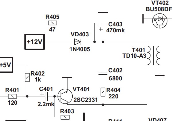
To check: C401, C403, VT401, T401, C402.
How to check the line transistor in the circuit beforehand without unsoldering? Between the base and the emitter, the multimeter will show a short circuit, since the resistance will be measured through a transformer, the transitions: Б-К and Э-К if they are in order, they will be “ringing” in one direction. But it is better to check all the same by drinking.
You can check the line transformer as follows, solder the transformer and instead solder the two legs of the TVS-110PTs15 transformer, the ninth and twelfth. We turn on the TV, and if a high voltage appears on the transformer, and the line transistor stopped heating, it is likely that the TDX burned out (provided that the strapping elements are in good order and be careful of output to a 8.5 kV multiplier).