External signs of the most characteristic faults can be divided into four groups:
1) the absence of a scan - on the screen instead of a raster, a narrow horizontal strip;
2) abnormal (reduced or enlarged) image size vertically.
3) linear image deterioration in the vertical;
4) violation of image synchronization by frames.
Methods of finding and troubleshooting are given on the example of TV-sets ULTPT-59-II, ULPZT-59-II (fig. 25), ULTPT-59-II-10/11, ULTPT-6-II and ULTPT (I) -61- II (Fig. 26).
Fig. 25. The layout of the frame sweep of TV sets ULTPTs-59-II, ULCPT-59-II.

Fig. 26. The layout of the frame scanning unit of the ULPCT-59-11-10 / II, UATPT-61-II, ULTPCT-61-II and ULPTST-61-II TVs
If there is no vertical image scan, you must first set whether the horizontal bar visible on the screen is shifted using the image vertical centering knob. If this band is not shifted, the following faults are possible: breaks in personnel deflection coils, in the primary winding of the transformer Tr3, in the winding circuit 1-2 of the transformer Tr2 and coil L4 of the pest-shaped distortion correction circuit, breakage of the collector terminal of the transistors of the terminal stage T5 (Fig. 26 ) and T4 (Fig. 25) or the absence of voltage at the output of a stabilized source that feeds a frame sweep.
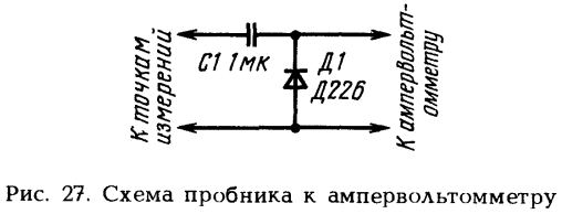
Fig. 27. Diagram of the probe to the multimeter.
If the centering regulator manages to mix the horizontal strip vertically, the vertical sweep may be absent due to the breakdown of the transistors T5 (fig. 26) and T4 (fig. 25) of the final stage or the closure of their radiators on the chassis, as well as master and intermediate stages of the frame scan. When connecting an ampere-volt meter connected to the measurement of constant voltages through a probe, which is a peak detector (Fig. 27), to various points of the circuit, one should make sure that there are alternating voltages shown on the oscillograms in the circuit diagram attached to the TV. Thus, in most cases, it is possible to find an idle cascade. A fault in such a cascade is found with an ampere volt meter, measuring the constant voltages shown on the circuit diagram at its various points.
A faulty semiconductor diode or transistor can be detected by measuring the transition resistance of the diode anode - cathode with the TV off and the collector - emitter, base - collector and base - emitter at the transistor. These resistances with direct and reverse switching of the amp meter in healthy diodes and transistors should be sharply different. If the resistances of the transitions in the forward and reverse directions are equally low and equally high, then between the electrodes of the transition diode or transistor is either a breakdown or a break. In addition, it is necessary to check the resistance between the emitter and the collector of the transistors, it should be large for any switching on the multimeter.
In some models of TV sets ULGSHT-61-II between the base and the emitter, as well as the collector and emitter of the transistor T4 included diodes of type D20 (dashed lines in Fig. 26). Due to the breakdown of these diodes, the vertical scanning will be absent. When measuring the resistance of the transitions of the transistor T4 and diodes connected in parallel with an diode with an ampere volt meter, one of the conclusions of these diodes should be unsoldered.
The serviceability of resistors can be checked by measuring their resistance with an amvolt meter. The same method can detect punched capacitors. Capacitors with dangling electrode leads can be detected by connecting serviceable ones with close-in capacitance in parallel with them and observing changes in the personnel sweep on the screen of a switched on TV.
The vertical size of the image may be insufficient due to the low voltage of the stabilized power supply of the vertical sweep, which is low against the norm or due to faults in the dynamic information circuit connected to the terminal stage of this sweep. In the second case, when disconnecting the parts of the connector Ш11 (fig. 25 and 26), the vertical image size increases dramatically. The same is observed in the presence of short circuits in the plug part of the connector Sh11. Vertical image size can be very small due to broken leads and loss of capacitance of capacitors C34 (fig. 25), C47 (fig. 26) or break of the resistor R84 (fig. 26). In the latter case, the vertical alignment of the image does not work.
The vertical size of the image may become excessively large due to increased stabilized power supply, increased breakage of the terminals, loss of capacitance C48 (fig. 26) or failure of resistor R44 or R69 (fig. 25) in the negative feedback circuit. In the event of a malfunction of the listed parts, there is, in addition, a noticeable nonlinearity of the image along the vertical.
Nonlinearity of the image, in which the raster is compressed from below, may appear due to overheating of the transistor case of the terminal stage T5 (fig. 26) or T4 (fig. 25) with its poor mechanical contact with the radiator, as well as due to inter-turn closures in the output transformer Tr3 The same with a simultaneous decrease in the size of the image along the vertical is observed when the winding 1-2 of the transformer Tr2 is broken. This is due to the inclusion in this case of the network of personnel deflecting coils of resistors R34, R35 (fig. 25) and R59, R60 (fig. 26) and the changing nature of the load of the terminal stage with transistor T4 (fig. 25) and T5 (fig . 26). The deterioration of the linearity of the image vertically during compression or stretching of the raster may occur due to poor quality (leakage or capacitance reduction) of capacitors C34, C48 (Fig. 26) and C33, C34 (Fig. 25).
Frame synchronization violations, which are expressed in the fact that image frames are shifted vertically quickly or slowly, may occur either due to the lack of frame sync pulses, or due to a decrease in their amplitude, or due to a large frequency deviation of the master oscillator of the frame sweep. If the frame rate knob is only able to stop or change the direction of frame shifting on the screen for an instant, then a synchronization failure occurred due to the lack of frame sync pulses or due to a decrease in their amplitude. In this case, the fault must be found in the clock selector, in the integrating filter or the emitter follower of the frame sync pulses in the UPCHI radio channel block. If, however, it is not possible to stop or change the direction of frame movement by rotating the “frame rate” knob, this indicates a large deviation of the frequency of the master oscillator of the vertical sweep.
The oscillation frequency of the master oscillator in the UAPTC-59-P-10/11/12, ULTPTsT-61-II and ULFTCTI-61-II TVs of all modifications (Fig. 26) is determined not only by the capacitance of capacitors C39, C46 and the resistance of resistors R67, R70 , R73, R71, but also the internal resistance of the transistors T1 and T2, which depends on the mode and current flowing through them. The transistors T1, T2 are connected in series and the current through them is determined by the resistance of resistors R70 and R67, included in the emitter circuit of the transistor T2. Therefore, with a large departure of the frequency of the master oscillator, it is necessary first of all to make sure that all the listed parts are in good condition. Only then can you change the resistance of the resistor R67 so that the frames of the image stop at the average position of the handle of the variable resistor R70. Through the movable contact of the resistor R70 flow currents of transistors T1 and T2. Therefore, if various faults occur in the master oscillator (the breakdown of one of the transistors, the capacitor C46, etc.), the current through the moving contact of the R70 resistor may exceed the allowable value and will burn some of the conductive layer of this resistor. After that, the frame rate adjustment using the Frame Rate knob will not occur smoothly and a strong drift of the frequency of the master oscillator may occur.
In television sets ULTPTsT-59-II and UPLTsTI-59-II (Fig. 25), the frequency of the master oscillator of the personnel sweep is determined by the capacitance of capacitor C31 and the rate of charge and discharge through resistors R37, R67, R39 and transitions of transistors T1 and T2. With a strong departure of the frequency of the master oscillator, you must first make sure that the parameters listed components are in good condition and correct, and only after that you can change the resistance of the resistor R39 so that the required frame rate is achieved with the average position of the moving contact of the variable resistor R67.
Due to the variation in the parameters of transistors T1 and T2 or other circuit elements, the frame rate adjustment range using variable resistors R70 (fig. 26) and R67 (fig. 25) can be shifted so that, when the clock pulses disappear, stop and change the direction of frame movement on the screen fails, and in the presence of clock pulses frames can be synchronized. In such cases, the cause of the malfunction can be detected by closing control points KT2 (Fig. 26) and KT5 (Fig. 25) for a short time on the chassis. If the frames will move around the screen even faster, the synchronization is not broken due to the lack of clock pulses.
If the frame movement speed during such a check remains unchanged, then it can be concluded that there are no clock pulses in the circuit with the specified checkpoints and the fault should be sought in the integrating filter or emitter follower of the frame sync pulses in the radio channel block.
Violation of frame scanning synchronization, as practice shows, also occurs for reasons not related to faults in the frame scanning node itself. For example, a significant frequency deviation of the master oscillator may occur due to a low or high voltage against the normal voltage of the stabilized power supply.
Continuous jitter or frame twitching vertically occurs usually due to improper setting of the AGC trigger threshold and an excessively large swing of the signal amplified in the TFIN. At the same time, large amplitude signals, which are frame and line sync pulses, are limited in the last stages of UPCHA almost to the level of damping pulses. Due to the use of the devices of the HSFC, the horizontal synchronization is not disturbed. At the same time, frame synchronization, in which the AFC & A devices are not used, is carried out both from damping and limited synchronizing pulses, which causes the image to shake vertically.
Twitching the frame vertically 1 every few seconds can be observed due to the deterioration of the filtering voltage generated in a stabilized power source. At the same time, a rather noticeable wide light or dark horizontal strip sometimes appears on the image along the vertical, which is formed due to the modulation of the video signal in the video amplifier of the variable component of the poorly filtered supply voltage. To eliminate such a malfunction, it is necessary to check the quality of electrolytic capacitors in a stabilized power source, as well as the reliability of the contact of their bodies with contact washers and the chassis. The unreliability of this contact, which occurs due to the weak tightening of the electrolytic capacitor attachment nuts or the appearance of scale on the contact surface, can lead to the fact that the malfunction does not exist all the time and sometimes appears only some time after the TV is turned on. Before tightening the fastening nuts, this scale should be cleaned with an emery paper or file.
Horizontal and vertical sweeps — indispensable components of any television receiver — have remained unchanged for many years in their principle of operation, the essence of which is to create sawtooth currents in the horizontal and personnel coils of a magnetic deflecting system. The latest generation of TVs and this part has undergone significant improvements based on the latest achievements of microelectronics and digital technology. In the first place, this concerns the small-signal circuits of the master generators of horizontal and vertical scanning.The purpose of the master oscillator is to launch powerful output sweep stages at precisely the times determined by the clock pulses in the received television signal. In modern TVs, this function, as well as many others related to the operation of the sweeps, is entrusted to a specialized microcircuit of the so-called sweep processor or abbreviated as DPU (Deflection Processing Unit). The ease of use of such a specialized chip is that it is possible to easily and quickly adjust the geometric parameters of a television image, as well as stabilize its size, monitor the operation of the kinescope and sweeps and turn off the power supply of the TV when dangerous modes occur.
A typical sweep processor is the SDA9064 chip used in the GRUNDIG TV set, the CUC1822 chassis, which performs the following functions:
- generation of signals for horizontal (E-W) correction of geometric distortions of the raster;
Fig. 9.1. SDA9064 Chip On Circuit on Cr18ig's GRUNDIG TV
The circuit of inclusion 1C SDA9064 is presented on fig. 9.1. All adjusting and geometrical parameters are transmitted after turning on the TV to the processor of sweeps on the bus 12C from the controlling central processor. The central processor, in turn, receives this data from its own storage device, where it is recorded in the manufacture of an EEPROM chip and corrected when performing adjustment and tuning operations.
The reference frequencies for the horizontal and vertical sweeps, or in other words, the horizontal and vertical clock pulses, respectively, come to the 7th and 9th pins of the microcircuit. The firing pulses for exciting the horizontal output stages are output from 4 pins. The reverse pulse from the horizontal transformer, after limiting the amplitude by the Zener diode D1406, is fed to pin 6 for automatic adjustment of the frequency and phase of the horizontal sweep.
The amplitude of the signal (E-W) correction is controlled for each raster line using a pulse width modulator (PWM) in the sweep processor. The PWM signal from the 35 output goes through the buffer stage to the module (E-W) - correction, which in turn outputs a correction current to the diode modulator of the horizontal sweep output stage.
The launching of a frame sweep is performed by a sawtooth signal, which is generated digitally using an internal clock generator of 3.6 MHz and an internal DAC. The sawtooth signal from the 36 output goes to 1C frame output stages, to which the deflection coils are connected directly (without a coupling capacitor). The feedback voltage from a resistor connected in series with the frame deflection coils is supplied via the VG line to pin 12 of IC1410. The sweep processor analyzes the feedback signal and, in accordance with the specified parameters, corrects the amplitude and linearity of the sawtooth signal.
To correct the size of the raster horizontally, the Ibeam signal is used, which is removed from a resistor connected in series with a 28 kV voltage source and fed to pin 13 of IC1410.
The input of the protection circuit connected to pin 2 of IC1410 has two threshold levels of 2.8 V and 3.6 V. During normal operation, the backward pulses and bursts of the signal present on this pin must be between the specified thresholds. If the voltage falls below the 2.8 V level, the kinescope is locked along the cathodes with a blanking SSC (Super Sandcastle) pulse, fed from 5 pins to the video module. If the upper threshold is exceeded, the sweep processor is blocked, stops outputting horizontal trigger pulses, and the horizontal sweep output stage is turned off.
In the SONY KV-S295 TV (AE-3 chassis), the sweep processor is integrated in the single chip package (SHA1840) with RGB signal processing devices that are output to the video amplifiers. Such a microcircuit combining a video signal processor and a scanning processor is called a kinescope driver (CRT-driver). We list its functions related to scans:
- generation of trigger pulses for line-output output stages;
- frequency control line scan (normal / double);
- automatic adjustment of the frequency and phase line scan;
- generation of a saw-tooth signal for frame output stages;
- Frame rate control (50 Hz / 100 Hz);
- generation of the parabolic signal of the horizontal (E-W) correction of geometric distortions of the raster;
- management of the geometric characteristics of the image;
- image size stabilization depending on the current of the kinescope rays;
- implementation of the modes “widescreen film”, “zoom” and “image movement”;
- protection of the kinescope from overvoltage, excess of the permissible current of the rays and from disturbances in the operation of the sweeps.

Fig. 9.2. Schematic diagram of the inclusion of the driver of the SCA1840 kinescope into the paths of the sweeps and video signals of the SONY KV28-VS3 TV
A diagram of the inclusion of the SKA1840 kinescope driver in the paths of the sweeps and video signals of the SONY KV28-VS3 TV set is shown in Fig. 9.2. The bright signal from the digital comb filter (3 outputs of the CXD2030R decoder IC) is fed to the 5 (VS-IN) and 6 (HS-IN) outputs of the CXA1845 through a buffer stage on the Q1531 transistor. These pins represent the inputs of the selector staff and lowercase sync pulses, and they must receive a luminance signal with a range of about 2 V, from which SHA1840 generates the following pulse and potential output signals:
Fig. 9.3. Using a key stage on a MOSFET to connect a deflection system in a TV SONY KV-S295
2 pin - identification signal - (0.4 V / 50 Hz; 3.3 V / 60 Hz);
Conclusion 7 - the output of the selector sync pulses (HSYNC);
8 pin - line frequency clock pulses (NT1M);
Conclusion 9 - sync pulses double line frequency (2HSYNC);
10 pin - SSCP color synchronization pulses;
11 pin - frame frequency clock (VTIM);
Output 34 - delayed frame rate clock (DTIM);
40 pin - line trigger pulses (HDOUT);
29 output - ramp signal master oscillator frame sweep (VSOUT);
Pin 31 - Parabolic Output Signal Generator (E-W) Correction (VPARA).
9.2. Output Sweep Stage
On TVs with a conversion standard, sweep playback works at twice the vertical (100 Hz) and horizontal (31.25 kHz) frequencies. Such an increase in the frequency of sweeps imposes specific requirements on the output stages of the formation of sawtooth currents in personnel and horizontal deflection coils.
Fig. 9.4. The principle of the key reverse gear (OX)
It is known that the resistance of the personnel coils of the deflecting system is mainly resistive in the periods of the forward course of the personnel sweep, and in periods of reverse, the inductance becomes the dominant component of the resistance. With an increase in the frequency of the frame sweep, the inductance of the coils significantly delays the duration of the return stroke, therefore it is necessary to reduce the output impedance of the sawtooth amplifier or to take other measures.
In particular, in order to ensure twice the duration of the reverse frame sweep at a given inductance of personnel deflection coils, in the TV SONY KV-S295 the deflection system is connected to the output of the vertical sweep chip 1C 1501 through a key stage on the powerful Q1505 MOSFET, as shown in fig. 9.3.
The principle of operation of the backstop key is illustrated in Fig. 9.4. With a sweep frequency of 100 Hz, the required voltage on the deflecting coils during the return period increases sharply (compared to 50 Hz) and cannot be provided by the chip of the output frame-scanning amplifier. An additional switch connected to the output of the amplifier in series with deflection coils, works in conjunction with the C1510 booster capacitor, increasing the amplitude of the reverse pulse as follows: Q1505 opens at the beginning of the reverse pulse and charges the C 1510 capacitor through diode D1503, increasing the supply voltage at pin 6 amplifier IC1501.
The full frame scan frame of the SONY KV-S295 TV set, which includes a kinescope protection device in the event of violations in the frame scan, is shown in fig. 9.5.
Linear output stages operating at double frequency of 31.25 kHz are performed mainly according to the same schemes as for the standard frequency 15.625 kHz. Of course, in this case, the requirements for high-power key transistors for the maximum allowable voltages and currents are stitched. The power supplied to the horizontal sweep increases, the losses in the transformer and in the power switches increase. The amplitude of the reverse pulse on the horizontal deflection coils can reach 1200-1300 V at the same current amplitude as in traditional TVs with a sweep of 15625 Hz; All this requires the use of a higher-voltage and more powerful transistor in the output stage.
In order to maintain the high reliability of line scanning, some manufacturers use the parallel connection of two high-voltage transistors (SAMSUNG CS721APTR / BWX TV). Another solution to the problem was found in PHILIPS MATCH LINE TV - the output stage is a key with a split load: part of the primary winding of a line transformer is included in the collector circuit of the output transistor, and the other part is in the emitter circuit of the same transistor.
Finding a defect is much more difficult than fixing it, especially for a beginner. The universal technique proposed by the author of the article will allow you to quickly and efficiently diagnose a modern TV.
C WHAT TO BEGIN
When repairing television receivers, there are situations when the TV does not turn on and does not show any signs of life. This greatly complicates the localization of the defect, especially considering that it is often necessary to repair imported equipment without schematic diagrams. The master is faced with the task of identifying the malfunction and eliminating it with the least amount of time and effort. To do this, you must follow a specific method for finding faults.
If a workshop or private master values his reputation, it is necessary to begin with cleaning the device. Armed with a soft brush and vacuum cleaner, you should clean the inner surface of the housing, the surface of the kinescope and the television receiver board. After thorough cleaning, an external inspection of the board and the elements on it is carried out. Sometimes it is possible to immediately determine the location of the malfunction by swollen or burst capacitors, by burnt resistors, or by transistors and microcircuits that have burned through. It happens that after cleaning the tube from dust instead of a transparent flask, we see a milky-white inner surface (loss of vacuum).
Much more often, a visual inspection does not reveal external signs of faulty parts. And then the question arises - where to start?
POWER SUPPLY
It is most advisable to start the repair with a test of the performance of the power supply. To do this, we disconnect the load (horizontal output stage) and connect instead an incandescent lamp of 220 V, 60 ... 100 W.
Normally, line feed voltage is 110 ... 150 V, depending on the size of the kinescope. After reviewing the secondary circuit, on the board next to the pulse transformer of the power supply we find the filter capacitor, which most often has a capacity of 47 ... 100 μF and an operating voltage of about 160 V. Near the filter is the horizontal power supply rectifier. After the filter, the voltage goes to the output stage through a choke, a limiting resistor or a fuse, and sometimes the board simply has a jumper. Having unsoldered this element, we will disconnect the output stage of the power supply unit from the horizontal scanning stage. In parallel to the capacitor, we connect an incandescent lamp - a load simulator.
When you first turn on the key transistor of the power supply may be damaged due to malfunction of the binding elements. In order to avoid this, it is better to turn on the power supply unit through another incandescent lamp with a power of 100 ... 150 W, which is used as a fuse and turned on instead of a soldered component. If there are faulty elements in the circuit and the current consumption is high, the lamp will light up and all the voltage will drop on it. In such a situation, it is necessary, first of all, to check the input circuits, the network rectifier, the filter capacitor and the high-power transistor of the power supply. If the lamp lights up when turned on and immediately goes out or starts to glow faintly, then we can assume that the power supply is healthy, and it is better to make further adjustments without the lamp.
Turning on the power supply, measure the voltage at the load. Take a close look at the board to see if there is an output voltage adjustment resistor around the power supply unit. Usually next to it is an inscription indicating the magnitude of the voltage (110 ... 150 V).
If there are no such elements on the board, pay attention to the presence of control points. Sometimes the value of the supply voltage is indicated next to the primary winding of the horizontal transformer. If the kinescope diagonal is 20 ... 21 ", the voltage should be in the range of 110 ... 130 V, and when the kinescope size is 25 ... 29", the supply voltage range is usually 130 ... 150 V.
If the supply voltage is higher than the specified values, it is necessary to check the integrity of the elements of the primary power supply circuit and the feedback circuit, which serves to set and stabilize the output voltage. You should also check the electrolytic capacitors. When dry, their capacity is significantly reduced, which leads to incorrect circuit operation and an increase in secondary stresses.
For example, on an Akai CT2107D TV, when the electrolytic capacitor C911 (47 μF, 50 V) dries out, the voltage in the secondary circuit instead of 115 V may increase to 210 V.
If the voltages are low, check the secondary circuits for short circuits or large leaks, the integrity of the protective diodes R2K, R2M in the horizontal power supply circuit and the protective diodes of 33 V in the power supply circuit of the vertical scan.
For example, on a Gold Star CKT 2190 TV, when a failed line filter power capacitor of 33 microfarads, 160 V, which has a large leakage current, the output voltage instead of 115 V was about 30 V.
On the Funai TV-2000A MK7, the R2M protective diode was pierced, which triggered the protection, and the TV did not turn on; in Funai TV-1400 MK10, the breakdown of a 33-volt protective diode in the vertical power supply circuit also led to the operation of protection.
LINE SCAN
Having dealt with the power supply and making sure that it is working, we restore the connection in the horizontal power supply circuit by removing the lamp that was used instead of the load.
To first turn on the TV, it is desirable to install an incandescent lamp used instead of a fuse.
With a good horizontal output stage, the lamp will turn on for a few seconds when turned on and will go out or will glow dimly.
If the lamp flashes when turned on and continues to burn, you need to make sure that the horizontal output transistor is in good condition. If the transistor is normal and there is no high voltage, make sure that there are control pulses on the base of the horizontal output transistor. If there are pulses and all voltages are normal, it can be assumed that the line transformer is faulty.
Sometimes this is immediately understandable by the strong heating of the latter, but it is very difficult to tell for certain whether the TDX is working properly or not. In order to determine this accurately, you can use the following method. We send rectangular pulses with a frequency of 1 ... 10 kHz of small amplitude to the collector winding of the transformer (you can use the oscilloscope calibration signal output]. We also connect the oscilloscope input to it.
With a good transformer, the maximum amplitude of the received differentiated pulses should not be less than the amplitude of the original rectangular pulses.
If TDKS has short-circuited coils, we will see short differentiated pulses with an amplitude of two or more times smaller than the original rectangular ones. This method can also determine the failure of transformers of the network pulse power supply units.
The method also works without watering out the transformer (of course, you need to make sure that there is no short circuit in the secondary strapping circuits).
Another horizontal fault, in which the power supply does not turn on and the lamp turned on instead of the fuse, glows brightly - the breakdown of the horizontal deflection coils. This fault can be identified by disconnecting the coils. If after that the TV turned on normally, then the deflecting system [OS] is probably faulty. To verify this, replace the deflecting system with a known-good one. TV at the same time you need to turn on for a very short time to avoid burn-through kinescope. Replacing the deflection system is not difficult. It is better to use the OS from a similar kinescope with a diagonal of the same size.
The author had to install in the Funai 2000 MKZ TV a deflecting system from a Philips 21-inch TV. After installing the new OS on the TV, it is necessary to adjust the convergence of the beams using a television signal generator.
PERSONNEL SCAN
If the line scan is normal, then at least the horizontal bar should be lit on the screen, and if the frame scan is healthy, the full raster should be on. If there is no raster and a bright horizontal stripe is visible on the screen, it is necessary to reduce the screen luminance by adjusting the accelerating voltage on the TDX. This is necessary in order not to burn the phosphor of the kinescope, and only after that you should look for a fault in the personnel scan.
Diagnostics in the frame scan unit should begin with checking the power of the master oscillator and the output stage. Most often, the power is taken from the winding of a line transformer. The supply voltage of these stages is 24 ... 28 V. The voltage is supplied through the limiting resistor, which must be checked first. Frequent malfunctions in the frame scan are breakdown or breakage of the rectifier diode and breakdown of the frame scan chip. Rarely, but still there is an interturn closure in personnel deflection coils.
If a deflecting system is suspected, it is better to check it by temporarily connecting a known good coil. Control should be made with an oscilloscope, observing the pulses directly on the frame coils.
KINESCOPE SUPPLY CHAINS
It happens that the power supply and scanner are OK, and the TV screen does not glow. In this case, it is necessary to check the voltage of the filament, and if it is present, the integrity of the filament of the kinescope.
In the author's practice, there were two cases when the filament winding of a horizontal transformer was broken (Sony and Waltham TVs). Do not rush to change the line transformer. To begin with, it should be carefully discharged, cleaned of dust and carefully inspect the incandescent windings.
Sometimes a cliff is located near the outlet under a layer of epoxy. Hot soldering iron gently remove part of the resin and, if a break is found, remove it, after which it is desirable to fill the repair site with epoxy resin.
If the break could not be found, you can wind the filament winding on the core of the same transformer. The number of turns is chosen empirically (usually it is 3 ... 5 turns, MGTF wire 0.14]. The ends of the winding can be fixed with glue or mastic.
RADIO CHANNEL, BLOCK OF COLOR, VIDEO AMPLIFIER
If the sweep is normal, the screen is lit, and there is no image, you can identify the faulty unit by the following features.
In the absence of sound and image malfunction must be sought in the radio channel (tuner and video processor).
If there is sound and no image is present, the fault should be looked for in a video amplifier or a color block.
If there is an image and there is no sound, the video processor or low-frequency amplifier is most likely faulty.
After checking the supply voltage of the radio channel, you need to send video and audio signals through a low-frequency input (you can use a television signal generator or a regular VCR).
If there is no image or sound, you should use the oscilloscope to trace the signal from the source from which the signal was sent to the cathodes of the kinescope or, if the sound channel is faulty, to the loudspeakers and, if necessary, replace the faulty element.
If after sending a signal to the low-frequency input, the image and sound appeared, then the fault should be sought in the previous stages.
When checking the video processor, the IF signal must be sent to the FSS input from the generator or from the tuner output of another TV.
If the image and sound did not appear, check the path of the signal with an oscilloscope and, if necessary, change the video processor (when replacing the chip, it is better to solder the socket).
If there is an image and sound, then the fault should be sought in the tuner or in its harness. First of all, you need to check whether the power is supplied to the tuner.
Check the serviceability of the key transistors through which the voltage comes to the tuner when switching bands. Check whether the signal from the control processor is sent to the bases of these transistors, check the magnitude and range of the setting voltage, which should vary between 0 ... 31 V.
When diagnosing faults tuner need to send a signal from the antenna to the mixer, bypassing the stages of the RF amplifier. For this it is convenient to use the probe, which can be made from a disposable syringe with a piston removed. At the top of the syringe, you must install the antenna jack and through the 470 pF capacitor connect the central contact with the needle. We take the earth by ordinary wire; for convenience, it is better to solder the crocodile clip to the earth wire. We connect the probe to the antenna plug and give a signal to the tuner cascades.
With the help of such a probe, it was possible to determine the fault in the tuner of the Grundig T55-640 OIRT TV. In this unit, the first UHF cascade was defective. The fault is eliminated by sending a signal through a 10 pF capacitor directly from the antenna jack, bypassing the first transistor to the next tuner stage. The image quality and sensitivity of the TV after such alterations remained quite high and did not even affect the operation of teletext.
CONTROL BLOCK
Especially it is necessary to dwell on the diagnosis of the TV control unit.
When it is repaired, it is desirable to use a circuit or reference data on the control processor. If you could not find such data, you can try to download them from the manufacturer's website of these components via the Internet.
A fault in the unit may manifest itself as follows: the TV does not turn on, the TV does not respond to signals from the remote control or the control buttons on the front panel, there are no volume adjustments, brightness, contrast, saturation and other parameters, there are no settings for TV programs, settings are not stored in memory , no indication of control parameters.
If the TV does not turn on, first of all check the availability of power on the processor and the operation of the clock generator. Then you need to determine whether the signal from the control processor to the switching circuit. To do this, find out the principle of turning on the TV.
The television can be turned on using a control signal that triggers the power supply, or by unblocking the passage of horizontal trigger pulses from the master oscillator to the horizontal scanning unit.
It should be noted that on the control processor, the turn-on signal is indicated either by Power or Stand-by. If the signal comes from the processor, then the fault should be sought in the switching circuit, and if there is no signal, the processor will have to be changed.
If the TV turns on, but does not respond to signals from the remote, you need to first check the remote itself. You can check it on another TV of the same model.
To test the remotes, you can make a simple device consisting of a photodiode connected to the CP-50 connector. The device is connected to the oscilloscope, the sensitivity of the oscilloscope is set within 2 ... 5 mV. The remote control should be directed to the LED from a distance of 1 ... 5 cm. On an oscilloscope screen, when the remote control is intact, pulse packets will be visible. If there are no pulses, we diagnose the console.
We successively check the power, the state of the contact tracks and the state of the contact pads on the control buttons, the presence of pulses at the output of the console chip, the health of the transistor or transistors, and the health of the emitting LEDs.
Often, after the fall of the console, the quartz resonator fails. If necessary, we change the defective element or restore the contact pads and button cover (this can be done by applying graphite, for example with a soft pencil, or by gluing metallized film on the buttons).
If the console is working, you need to trace the passage of the signal from the photodetector to the processor. If the signal reaches the processor, and nothing changes at its output, it can be assumed that the processor is faulty.
If the TV is not controlled from the buttons on the front panel, you must first check the health of the buttons themselves, and then trace the presence of polling pulses and feed them to the control bus.
If the TV is turned on from the console and the pulses arrive at the control bus, and the on-line adjustments do not work, you need to find out by what output the microprocessor controls this or that adjustment (volume, brightness, contrast, saturation). Next, check the paths of these adjustments, up to actuators.
The microprocessor generates control signals with a linearly varying duty cycle, and acting on actuators, these signals are converted to a linearly varying voltage.
If the signal arrives at the actuator, and the device doesn’t react to this signal, then this device is repaired, and if there is no control signal, the control processor is replaced.
If there are no settings for TV programs, we first check the subrange selection node. Usually, through buffers implemented on transistors, voltage is supplied from the processor to the tuner pins (0 or 12 V). Most often these transistors fail. But it happens that there are no subband switching signals from the processor. In this case, you need to change the processor.
Next, check the node generating voltage settings. The supply voltage usually comes from the secondary rectifier from the horizontal transformer and is 100 ... 130 V. From this voltage, 30 ... 31 V are formed with the help of a stabilizer.
The microprocessor controls the key that generates a setting voltage of 0 ... 31 V using a signal with a linearly varying duty cycle, which, after the filters, is converted into a linearly varying voltage.
The stabilizer of 30 ... 33 V most often fails. If the settings in the memory are not saved in the TV, it is necessary to check the data exchange between the control processor and the memory microcircuit via the CS, CLK, D1, DO buses at any setting. If there is an exchange, and the values of the parameters in the memory are not stored, replace the memory chip.
If there are no control parameters in the TV, it is necessary in the display mode to check the presence of video impulses of service information on the control processor via the R, G, B circuits and the luminance signal, as well as the passage of these signals through buffers to the video amplifiers.
In this article we touched upon a small part of the faults that are found in television receivers. But in any case, the method of finding them will help you correctly identify and eliminate the fault and will reduce the time spent on repairs.
"Repair of electronic equipment"
Frame scan
If the line scan is normal, then at least the horizontal bar should be lit on the screen, and if the frame scan is healthy, the full raster should be on. If there is no raster and a bright horizontal stripe is visible on the screen, it is necessary to reduce the screen luminance by adjusting the accelerating voltage on the TDX. This is necessary in order not to burn the phosphor of the kinescope, and only after that you should look for a fault in the personnel scan.Diagnostics in the frame scan unit should begin with checking the power of the master oscillator and the output stage. Most often, the power is taken from the winding of a line transformer. The supply voltage of these stages is 24 ... 28 V. The voltage is supplied through the limiting resistor, which must be checked first. Frequent malfunctions in the frame scan are breakdown or breakage of the rectifier diode and breakdown of the frame scan chip. Rarely, but still there is an interturn closure in personnel deflection coils.
If a deflecting system is suspected, it is better to check it by temporarily connecting a known good coil. Control should be made with an oscilloscope, observing the pulses directly on the frame coils.
06/11/2010 - 21:14
Frame scan.
Frame scan.
Frame scan (CD) TV forms a sawtooth current, which flowing through personnel coils (QC) deflecting system (OS) provides vertical scanning, and also produces pulse voltages used in the channels of brightness and color to link the black level and color synchronization and in some models for the correction of the raster.
Structurally, in most cases, personnel scanning is performed on a microchip with strapping elements. The most common microcircuits are: TA8403, LA7830, LA7837, LA7838, TDA3653, TDA3654, AN1555, STV9302 (TDA9302), TDA8351, TDA8356.
The microcircuit is usually powered from the secondary voltage source, that is, from the TDCS, less often from the secondary IP. Accordingly, when a personnel chip fails, the supply voltage is checked. The reasons for the failure can be: A) lack of stabilization in the primary and secondary IP, B) non-compliant line pulse based on HOT, C) TDKS itself and its harness.
The power supply of the microcircuit can be both unipolar-plus and earth and bipolar-plus-minus-earth. Bowl output from the midpoint of the OS load ground. Less commonly, the inclusion of the bridge, between the two pins of the chip without the earth.
Frame scan on the LA7840 Avest 54-03.
Food staffing 6 pin +24 volts with TDKSa 6 pin, D402, C413. This chip (like many others) is very similar in architecture to ULF, especially the pre-output stage includes a phase-inverter transistor, which forms positive and negative half-waves, and the output stage is made on two transistors, one amplifying a positive half-wave, the other negative, such the same circuit for switching on ULF class B. The load is connected from the midpoint of a 2 pin chip (voltage is slightly more than half the supply voltage of the chip) on one side of the QC OS, on the other electrolytic capacitor C308 through a small RN133 resistance to earth.
1) the failure of the chip. Causes: a) overestimated voltage from secondary IP or from TDKS, b) loss of capacitance C302.
2) the temperature of the chip in the PP very quickly become critical. The reason is in the chain R314, C301, breakage of one of the parts. Checked by replacement.
4) When turned on (on the "cold") on top of the strip on the screen. With warming, the number of lanes decreases. The reason is the capacitor C302.
5) Nonlinearity varying or not with heating. Cause electrolytes.
Personnel development on TDA9302 Falcon 54ТЦ6254 chassis A2025.
Personnel power supply bipolar plus 2 pin chips +124 volts with TDKSa 5 pin, VD411, C417, minus 4 pin chips -12 volts with TDKSa 3 pin, VD410, C418. This chip is similar to the previous one in architecture and is very similar to ULF, the output stage is made on two transistors, one amplifies a positive half-wave, the other is negative, the same ULF class B switching circuit. The load is turned on from the midpoint of a 5 pin chip (voltage zero) on one side QC OS, on the other hand through low impedance resistance R407 and R408 to ground.
The most common defects in this and similar schemes include personnel:
1) the failure of the chip. Causes: a) overestimated voltage from secondary IP or from TDKS, b) loss of capacitance C409.
2) the temperature of the chip in the PP very quickly become critical. The reason is in the chain R404, C411, breakage of one of the parts. Checked by replacement.
3) When tapping or working, the frame (horizontal bar) disappears. The reason is bad soldering of the microchip itself.
4) When turned on (on the "cold") on top of the strip on the screen. With warming, the number of lanes decreases. The reason is the capacitor C409.
5) Nonlinearity varying or not with heating. Cause electrolytes. First checked on nutrition! C417 and C418.
Attached files:
21/08/2012 - 15:54
Frame scan. Bridge inclusion.
Ruby M10 chassis.
TDA8356 is enabled by a bridge circuit, that is, output to the QC OS with 7 and 4 pins of the chip, without land! The chip has two power supply 3 pin +15 volts with 5 pins of TDKS VD710, C711 and 6 pin +45 volts with 7 pins of TDKS VD709, C710.
SM Ruby Chassis M10
"The master oscillator of the frame scan is included in the IC D101 and has external driver circuits - a resistor R102 connected to its pin 25 and a capacitor C112 across pin 26. The voltage from the master portion of the frame scan - from pin 21 and 22 of the IC D101 - is fed to pin 2 and 1 IC D600 type TDA8356 - frame output amplifier. IC D101 has a current control signal output, with output 46 being the reference, and output 47 - signal. The signal voltage, which is the input for the IC D600, is allocated on the resistor R601. Capacitors C601 , C602 reduce levels The power of the D600 amplifier from horizontal scanning that can increase the current consumption of the DA600 IC and overheat it. The capacitor C606 ... C609 and the resistor R604 prevent the amplifier from self-excitation at high frequencies. The output stage in the DA600 IC is bridged and its outputs (outputs 4 and 7 of the DA600 ICs are connected to personnel OS deflecting coils via a current feedback resistor R602. Pin 9 is an input of a current feedback circuit providing high accuracy of matching the shape of the output current of the amplifier and the voltage at its input. The TDA8356 IC passes the input signal from the input (pins 1, 2) to the output (pins 4, 7) without losing the DC component, which makes it possible to “center” the image across the frame by changing the DC component of the input signal at pin 1 relative to pin 2 of the D600 IC. This adjustment is made in the D101 IC. IC D600 has two supply voltages - power of the amplifier itself - pin 3 (+ 15V) and power supply of the backward generator - pin 6 (+ 45V). The use of increased supply voltage to power the output stage during the reverse stroke ensures its short duration — less than 1 ms. During operation of this circuit, short, about 1 ms, frame frequency pulses with an amplitude up to 5V occur at output 8 of the DA600 IC, which are fed through the emitter follower VT102 and diode VD102 to pin 50. In the event of a malfunction in the frame sweep, a constant voltage appears at pin 8 , which, according to conclusion 50, blocks the operation of the TV, thereby protecting the kinescope from the burn-through of the phosphor by excessive beam current. The duration of the reverse pulse arriving at pin 50 should not exceed 900µs, since when this value is exceeded, the pulse begins to affect the operation of the automatic white balance circuit. "
The most common defects in this and similar schemes include personnel:
1) the failure of the chip. Reasons-overvoltage with secondary IP or with TDKS.
2) the temperature of the chip in the PP very quickly become critical. The reason is in the chain R605, C310, breakage of one of the parts. Checked by replacement.
3) When tapping or working, the frame (horizontal bar) disappears. The reason is bad soldering of the microchip itself.
5) Nonlinearity varying or not with heating. Cause electrolytes. First of all check on the power supply of 15 volts and 45 volts!