Variable electricity, as well as alternating voltage, change their direction and value over a certain period of time.
Since this resource is more applied than theoretical in nature, here the topic of alternating electric current and voltage will be considered in a volume sufficient to understand the essence of these processes and nothing more.
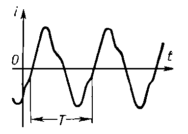
Changes in current (voltage) over time can be quite complex, but it is always possible to represent them as a set of a series of oscillations that change according to a sinusoidal law (Fig. 1). The voltages and currents that we use in Everyday life subject to the same law.
Let's take an arbitrary point and begin to rotate it in a circle with angular velocity ω (Figure 1.a). At the same time, it will sequentially pass all points of the circle, including 1,2,3,4, after which the cycle will repeat. If we project all this onto the X (current or voltage value) and t (time) axes, we get the graph shown in Figure 1 (these points are also marked there), which explains the essence of alternating current or voltage.
The time T=t4-t1 during which one oscillation cycle occurs is called a period. The dependence of the period on the oscillation frequency is inversely proportional to T=1/f, where f is the oscillation frequency (a value characterized by the number of oscillations per unit time). The unit of frequency is Hertz (Hz). 1 Hertz is one oscillation per second.
The oscillation frequency in the Russian AC network is 50 Hz. (In some countries, the current frequency is 60 Hz.)
Now, actually about why I gave the example of rotating a point around a circle. Suppose we need to determine the relative position of point 1 from point 2. It seems tempting to tie them to the t axis, then we get the distance between them Δt=t2-t1, but for different frequencies this value will be different.
If we take into account that a full revolution is always equal to 360 0 or 2π radians, then we can always say that point 2 is shifted relative to point 1 by 90 0 (π/2). By the way, it's called phase shift and will be useful to us when considering three-phase current (or voltage - whatever).
It's time to move on to Figure 2. Everyone knows that the voltage of the household electrical network is alternating and should be 220 V. So, if you think that this value can be assigned to point A, then you are mistaken. Judge for yourself, the alternating voltage either increases or decreases, at some moments it is completely zero, but it does its job.
This work is determined by the area (yellow) bounded by the sine wave and the t-axis (zero value). If you build a rectangle of the same area (shaded), then its upper boundary, located at mark a (small) will correspond to the value of 220V. It is called effective voltage value.
The amplitude value of the voltage is higher, the relationship between them is determined by the formula A=a*√ 2 , that is, the maximum voltage value in the network can reach 311 V. This is true for any alternating voltages, which should be taken into account, for example, when choosing the maximum permissible reverse voltage of the diode when connecting it to an alternating current circuit.
THREE-PHASE CURRENT
In conclusion - a little about three-phase current . This is exactly what we produce on an industrial scale. The three-phase current generator has three coils located at an angle of 120 0 (Figure 3). Accordingly, in each of them, when rotating in a magnetic field, an electric current is induced. The coil currents are phase shifted relative to each other by the same 120 0.

When connecting three-phase energy consumers, it is necessary to take into account the order of connecting the phases. The connection sequence may have the following options:
This is due to the fact that alternating three-phase current is capable of creating a rotating magnetic field; if connected incorrectly, the direction of its rotation will change to the opposite, which may lead to malfunction of some devices.
It is worth saying that a household single-phase electrical network is nothing more than part of a three-phase circuit that uses a neutral (N) wire and one of the phases A(L1), B(L2), C(L3) for operation. When connecting single-phase consumers, the load should be evenly distributed between all three phases.
The question may arise: why does a three-phase circuit have a voltage of 380V, and a single-phase circuit 220V? The fact is that the voltages between phases U AB, U AC, U BC are 380 Volts, and between any phase and “zero” U AN, U BN, U CN - 220 Volts. That is why an erroneous connection of one of the phases to the neutral wire can damage household appliances designed for 220V voltage.
© 2012-2017 All rights reserved.
All materials presented on this site are for informational purposes only and cannot be used as guidelines or regulatory documents.
For transmission and distribution electrical energy P.T. is primarily used due to the ease of transforming its voltage with almost no power losses (see Electricity transmission, Electric circuit). Widely used three-phase systems P. t. (see Three-phase circuit). Compared to direct current machines (see Direct current), DC generators and motors with equal power are smaller in size, simpler in design, more reliable, and cheaper. DC voltage can be rectified, for example, with semiconductor rectifiers, and then, using semiconductor inverters, converted again into DC voltage of a different, adjustable frequency; This makes it possible to use simple and cheap brushless DC motors (asynchronous and synchronous) for all types of electric drives that require smooth speed control.
Direct telephony is widely used in communication devices (radio, television, long-distance wire telephony, etc.).
P. t. is created by alternating voltage. An alternating electromagnetic field arising in the space surrounding current-carrying conductors causes energy fluctuations in the electrical circuit: energy periodically accumulates in the magnetic or electric field, then returns to the source of electricity. Energy fluctuations are created in the P. t. circuit. reactive currents, which uselessly load the wires and the current source and cause additional energy losses, which is a disadvantage of P. t. energy transfer.
The basis for characterizing the power of a direct current is a comparison of the average thermal effect of a direct current with the thermal effect of a direct current of the corresponding strength. The value of the force of the P. t. obtained in this way. I called the effective (or effective) value, which mathematically represents the root-mean-square value of the current over a period. The effective value of the DC voltage is determined similarly. U. Pt ammeters and voltmeters measure precisely the effective values of current and voltage.
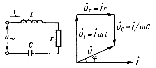
In the simplest and most important case in practice, the instantaneous value of the force i P.t. changes over time t according to the sinusoidal law: i = Im sin ( ωt + α ), Where I m - current amplitude, ω = 2 π f- its angular frequency, α - initial phase. A sinusoidal (harmonic) current is created by a sinusoidal voltage of the same frequency: u = Um sin ( ωt+ β ), Where U m - voltage amplitude, β - initial phase ( rice. 2 ). The effective values of such a P. t. are equal to: I = l m /√2 ≈ 0,707 Im, U = Um/√2 ≈ 0,707 Um. For sinusoidal currents satisfying the quasi-stationary condition (see Quasistationary current ; in the future, only such currents will be considered), Ohm’s law is valid (Ohm’s law in differential form is also valid for non-quasi-stationary currents in linear circuits). Due to the presence in the DC circuit of inductance and/or capacitance between the current i and tension u in general, a phase shift occurs φ = β - α , depending on the circuit parameters (active resistance r, inductance L, containers WITH) and angular frequency ω . Due to the phase shift, the average power R T. t., measured by a wattmeter, is less than the product of the effective values of current and voltage: R = IU cos φ .
In a circuit containing neither inductance nor capacitance, the current is in phase with the voltage ( rice. 3 ). Ohm's law for effective values in this circuit will have the same form as for a direct current circuit: I = U/r. Here r- active resistance of the circuit, determined by active power R, spent in the circuit: r = P/I 2 .
If there is inductance in the circuit L P. t. induces a self-induction emf in it e L=-L. di/dt = - ωLl m cos( ωt + α)= ωLI m sin ( ωt + α - π /2). The self-inductive emf opposes changes in current, and in a circuit containing only inductance, the current is out of phase with the voltage by a quarter of a period, that is φ =π /2 (rice. 4 ). Effective value e L equals E L = IωL=IxL, Where x L = ωL - inductive reactance of the circuit. Ohm's law for such a circuit has the form: I = U/x L = U/ωL.
When capacity WITH energized u, then its charge is equal q = Cu. Periodic changes in voltage cause periodic changes in charge, and a capacitive current occurs i = dq/dt = C․du/dt =(CU m cos( ωt + β ) = ωCU m sin ( ωt + β+ π /2). Thus, a sinusoidal DC current passing through a capacitance is ahead in phase of the voltage at its terminals by a quarter of a period, that is φ = -π /2 (rice. 5 ). The effective values in such a circuit are related by the relation I = ω CU = U/x c , Where x c = 1/ωС- capacitance of the circuit.
If the P. t. circuit consists of series-connected r, L And WITH, then its total resistance is equal to , Where x = x L - x c = ωL - 1 / ω C - reactance of the circuit P. t. Accordingly, Ohm's law has the form: and the phase shift between current and voltage is determined by the ratio of the reactance of the circuit to the active one: tg φ = x/r. In such a circuit, if the frequency coincides ω forced oscillations created by a P. t. source with a resonant frequency ω 0 = 1/ωL = 1/ ωС) and completely compensate each other, the current strength is maximum and the phenomenon of resonance is observed (see Oscillatory circuit). Under resonance conditions, the voltages across the inductance and capacitance can significantly (often many times) exceed the voltage at the circuit terminals.
Facilitation of calculations of sinusoidal power supply circuits is achieved by constructing so-called vector diagrams (see Vector diagram). Vectors of sinusoidal current and voltage are usually marked with a dot above letter designation(I and U, and the angles between the vectors are equal to the phase shifts between the instantaneous values of the corresponding quantities. The algebraic addition of instantaneous values of sinusoidal quantities of the same frequency corresponds to the geometric addition of the vectors of these quantities. On rice. 6
shown vector diagram for a P.T. circuit with series-connected r, L, WITH. The instantaneous voltage value at the terminals of this circuit is equal to the algebraic sum of the voltages at the active and reactance: u = u L + u r + u c , hence, ![]() π/2, and capacitive lags behind the current by π
/2 (that is, they are in antiphase), with serial connection they partially compensate each other.
π/2, and capacitive lags behind the current by π
/2 (that is, they are in antiphase), with serial connection they partially compensate each other.
Vector diagrams clearly illustrate the progress of calculations and serve to control them; built to scale, they allow you to graphically determine the effective stress U in the circuit and phase angle φ.
Kirchhoff's rules are used for calculations of branched circuits of quasi-stationary power supply systems. In this case, the method of complex quantities (symbolic method) is usually used, which makes it possible to express in algebraic form geometric operations with DC vectors and thus apply all methods for calculating direct current circuits to calculate DC circuits.
Non-sinusoidal power in electric power systems is usually undesirable, and special measures are taken to suppress it. But in telecommunication circuits, in semiconductor and electronic devices, non-sinusoidality is created by the working process itself. If the average value of the current over a period is not zero, then it contains a constant component. To analyze processes in non-sinusoidal current circuits, it is represented as a sum of simple harmonic components, the frequencies of which are equal to integer multiples of the fundamental frequency: I = i 0 + I 1m sin ( ωt +α 1)+ I 2m sin ( 2ωt +α 2) +... + l km sin ( kωt + α k). Here I 0- constant current component, I'm sin ( ωt + α 1) - the first harmonic component (fundamental harmonic), the remaining terms are higher harmonics. Calculation of linear circuits of non-sinusoidal current based on the principle of superposition (imposition) is carried out for each component (since x L And x c depend on frequency). Algebraic addition of the results of such calculations gives the instantaneous value of the strength (or voltage) of the non-sinusundal current.
Lit.: Theoretical basis electrical engineering, 3rd ed., part 2, M., 1970; Neiman L.R., Demirchan K.S., Theoretical foundations of electrical engineering, vol. 1-2, M.-L., 1966; Kasatkin A.S., Electrical engineering, 3rd ed., M., 1974; Polivanov K.M., Linear electrical circuits with lumped constants, M., 1972 (Theoretical foundations of electrical engineering, vol. 1).
A. S. Kasatkin.


Great Soviet Encyclopedia. - M.: Soviet Encyclopedia. 1969-1978 .
See what “Alternating current” is in other dictionaries:
In a broad sense, an electric current that varies over time. P. t. AC is created. tension. In technology, current is usually understood as periodic current, in which the average values of current and voltage over a period are equal to zero. Period T P. t. called... ... Physical encyclopedia
In a broad sense, an electrical current that varies over time; in a narrow periodic current, the average value over the period is zero. The most commonly used is sinusoidal alternating current … Big Encyclopedic Dictionary
alternating current- Electric current that changes over time. Note: Variables are defined in the same way electrical voltage, electromotive force, magnetic flux, etc. [GOST R 52002 2003] Topics of electrical engineering, basic concepts Synonyms... ... Technical Translator's Guide
See AC current. Samoilov K.I. Marine dictionary. M.L.: State Naval Publishing House of the NKVMF of the USSR, 1941 ... Marine Dictionary Encyclopedic Dictionary of Metallurgy
In a broad sense, an electrical current that varies over time; in a narrow periodic current, the average value over the period is zero. The most commonly used is sinusoidal alternating current. * * * ALTERNATING CURRENT ALTERNATING CURRENT, in a wide… … encyclopedic Dictionary
Electric current that periodically changes in strength and direction. In a broad sense, alternating current is any current that changes over time. The main method of transmitting electricity is associated with the use of alternating current due to the relative... ... Encyclopedia of technology
alternating current- kintamoji srovė statusas T sritis automatika atitikmenys: engl. alternating current vok. Wechselstrom, m rus. alternating current, m pranc. courant alternatif, m … Automatikos terminų žodynas
What is alternating current. Definition of alternating current
Alternating current is the directed movement of charged particles, the direction of movement of which is reversed at regular intervals. If D.C. flows in one direction and does not change in magnitude, then alternating current can be in this moment positive, and after a certain period of time negative.
Generators produce alternating current AC voltage, which convert mechanical energy into electrical energy. The form of alternating current can be different and depends on its purpose. The form of alternating current for industrial purposes and for domestic needs of the population is sinusoidal in nature.
It has such characteristics as amplitude, frequency and period. The period of a sinusoidal current is its full cycle of oscillation and is measured by the time it takes to complete one cycle of oscillation. Such cycles are repeated and therefore alternating current is also called cyclic.
The period is designated by the letter T and is expressed in seconds. Another parameter of sinusoidal current is frequency, which is inversely proportional to the period, i.e. F = 1/T. If the period of alternating current is 1 second, then its frequency will be 1 Hz.
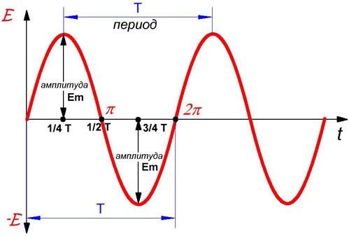
There are two AC standards - 50 Hz and 60 Hz. In Russia, the network frequency is 50 Hz, and in Canada and the USA it is 60 Hz. A parameter such as amplitude is determined by its greatest value in a certain period of time; it can have a negative or positive value.
What is three phase alternating current
If two sinusoidal signals simultaneously reach their highest amplitude and zero, then we can say that these signals have the same phase, that is, they are in phase. If these signals have different maximum and zero values, then they are out of phase.
In three-phase alternating current there are three signals of single-phase sinusoidal current shifted relative to each other by 120°. From polyphase electrical networks Basically, a three-phase network was chosen as the most optimal. A three-phase network consists of 3 single-phase networks.
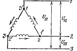
like this single-phase network in a three-phase network is called a phase. There are two possible types of phase connections in a three-phase network - a “triangle” and a “star” connection. When connected by a star, some ends of the generator are connected together and form a zero point, and the other wires of the windings going to the loads are called linear.
The voltage between the line wires and the neutral wires is called phase voltage. And the voltage between linear wires is called line voltage. The neutral wire is used in cases of uneven load, allowing the phase voltage to be equalized.
The neutral wire is used in a lighting circuit, where it is not easy to create a uniform load, since not all lamps turn on simultaneously and evenly in phases. There is a relationship between phase and line voltages: Ul = √3*Uph ≈ 1.73*Uph. IN three-phase networks according to the “star” circuit, Ul is 380 V, and Uph = 220 V.

If the load is electrical circuit according to the “star” circuit in three phases is the same, i.e. symmetrical, then there is no current in the neutral wire, or it is of a minimum value. And if the neutral current is insignificant, then the cross-section of the neutral wire is significantly smaller than the cross-section of the linear wire. When the load is the same, the current in the neutral will be zero.
Neutral is not needed in this case. Then they use a “triangle” connection diagram for a three-phase network, where all ends are connected to the beginning of the generator windings and form a “triangle” diagram without a neutral. In a delta circuit, phase and line voltages are equal to Ul = Uph, and the currents are determined by the formula - IЛ = √3*IF, where the linear current is 1.73 times greater than the phase current.
The delta connection is sometimes used in lighting, but mainly this circuit is used in three-phase networks with a slight phase imbalance. Also, heavy starting of asynchronous electric motors is carried out according to the “star” scheme in order to reduce the large starting current electric motor, and having reached the operating mode, they switch to the “triangle” circuit.