Low-power converter for powering a 9-volt load from a 3.7-volt Li-ion battery
Some modern low-power devices consume a very small current (a few milliamperes), but they require a too exotic source for their power — a 9-volt battery, which also lasts a maximum of 30 ... 100 hours of operation. Especially strange it looks now, when Li-ion batteries from a variety of mobile gadgets are almost cheaper than the batteries themselves - the batteries. Therefore, it is natural that a real radio amateur will try to adapt the batteries to power his device, and will not periodically look for "antique" batteries.
If we consider a normal (and popular) multimeter as a low-power load. M830, powered by an element of the type "Corundum", then to create a voltage of 9 V you need at least 2-3 series-connected batteries, that we don’t fit, they just don’t fit inside the device case. Therefore, the only way to use a single battery and boost voltage converter.
Select element base
The simplest solution is to use a type 555 timer (or its CMOS version 7555) in a pulse converter (capacitive converters do not suit us; there is too much difference between the input and output voltages). It has an additional “plus” of this microcircuit with an open-collector output, and a high enough voltage capable of withstanding voltages up to +18 V at any operating supply voltage. Thanks to this, it is possible to assemble a converter from literally a dozen of cheap and common parts (Fig. 1.6).
Fig. 1.6. Simple converter circuit
Pin 3 of the chip is a normal two-state output, it is used in this circuit to support generation. Pin 7 is an open collector output capable of withstanding overvoltage, so it can be connected directly to the coil, without a repeater on the transistor. The reference voltage input (pin 5) is used to regulate the output voltage.
Principle of operation of the device
Immediately after the supply voltage is applied, capacitor C3 is discharged, the current through Zener diode VD1 does not flow, the voltage at the REF input of the chip is 2/3 of the supply voltage, and the duty cycle of the output pulses is 2 (i.e., the pulse duration is equal to the pause duration) . Diode VD2 is needed to ensure that the discharged capacitor C3 does not affect the circuit (did not reduce the voltage at pin 5), the R2 resistor "just in case", for protection.
As this capacitor charges, the Zener diode VD1 begins to open slightly, and the voltage at pin 5 of the chip rises. From this, the pulse duration decreases, the pause duration increases until dynamic equilibrium occurs and the output voltage stabilizes at a certain level. The magnitude of the output voltage depends only on the voltage stabilizing the Zener diode VD1 and can be up to 15 ... 18 V with a higher voltage chip can fail.
About the details
The coil L1 is wound on a ferrite ring. K7x5x2 (outer diameter - 7 mm, inner - 5 mm, thickness - 2 mm), approximately 50 ... 100 turns with a wire with a diameter of 0.1 mm. The ring can be taken and more, then the number of turns can be reduced, or you can take an industrial choke with the inductance of hundreds of microgens (μH).
The 555 chip can be replaced with a domestic analogue of the K1006VI1 or the CMOS version 7555 - it has less current consumption (the battery will "hold on" a little longer) and the operating voltage range is wider, but it has a weaker output (if the multimeter needs more than 10 mA it may not to produce such a current, especially with such a small supply voltage) and it, like all CMOS structures, "does not like" the increased voltage at its output.
Features of the device
The device starts to work immediately after assembly, the whole setup consists in setting the output voltage by selecting the Zener diode VD1, while the output parallel to the capacitor C3 is to connect a 3.1 kOhm resistor (load simulator), but not a multimeter!
It is forbidden to turn on the converter with a non-soldered Zener diode, then the output voltage will be unlimited and the circuit may “kill” itself. You can also increase the operating frequency by reducing the resistance of resistor R1 or capacitor C1 (if it is operated at an audio frequency, a high-frequency beep is heard). When the length of the wires from the battery is less than 10 ... 20 cm, the filtering power capacitor is optional, or it is possible to put a capacitor of 0.1 microfaram or more between pins 1 and 8 of the microcircuit.
Identified deficiencies
First, the device contains two oscillators (one master oscillator of an ADC chip — an analog-digital converter of the instrument, a second converter oscillator) operating at the same frequencies, that is, they will affect each other (frequency beat) and the measurement accuracy will seriously deteriorate.
Secondly, the frequency of the converter oscillator constantly changes depending on the load current and battery voltage (because there is a resistor, and not a current generator, in the POS circuit - a positive feedback), therefore it is impossible to predict and correct its influence. Specifically for a multimeter, one common generator for an ADC and a converter with a fixed operating frequency would be ideal.
The second version of the converter
The circuit of such a converter is slightly more complicated and is shown in fig. 1.7.
Fig. 1.7. Converter circuit with a fixed operating frequency
On the element DD1.1 a generator is assembled, through the capacitor C2 it closes the converter, and through C5 - the ADC microcircuit. Most of the inexpensive multimeters are based on the ICL7106 dual-integration ADC or its analogs (40 pins, 3.5 characters on the display), to clock this chip, you just need to remove the capacitor between pins 38 and 40 (solder its leg from pin 38 and solder to the pin 11 DD1.1). Due to the feedback through the resistor between pins 39 and 40, the microcircuit can be clocked even by very weak signals with an amplitude of a fraction of a volt, therefore 3-volt signals from the output of DD1.1 are quite enough for its normal operation.
By the way, this way you can increase the measurement speed 5 ... 10 times - just by increasing the clock frequency. The accuracy of the measurement does not practically suffer from deteriorating by a maximum of 3 ... 5 lower order units. It is not necessary to stabilize the operating frequency for such an ADC, therefore a conventional RC oscillator is quite sufficient for normal measurement accuracy.
On the elements DD1.2 and DD1.3 assembled standby multivibrator, the pulse duration of which with the help of the transistor VT2 can vary almost from 0 to 50%. In the initial state, at its output (pin 6) there is a "logical unit" (high voltage level), and capacitor C3 is charged through the diode VD1. After a triggering negative pulse arrives, the multivibrator “tilts”, a “logical zero” (low voltage level) appears on its output, the blocking multivibrator through pin 2 DD1.2 and the opening transistor VT1 through the inverter on DD1.4 In this state, the circuit will be until until the capacitor C3 is discharged - after which the "zero" at pin 5 of DD1.3 "knocks over" the multivibrator back to the standby state (by this time C2 will have time to charge and at pin 1 of DD1.1 it will also be "1"), transistor VT1 will close and the coil L1 is discharged to condensate C4 p. After the arrival of the next pulse, all the above processes will repeat.
Thus, the amount of energy stored in the coil L1 depends only on the discharge time of the capacitor C3, that is, on how strong the transistor VT2 is, helping it to discharge. The higher the output voltage, the stronger the transistor opens; thus, the output voltage is stabilized at a certain level depending on the voltage stabilizing the Zener diode VD3.
To charge the battery, use the simplest converter on the adjustable linear stabilizer DA1. Charge the battery, even with frequent use of a multimeter, you only have a couple of times a year, so there is no point in putting a more complex and expensive pulse stabilizer here. The stabilizer is set to an output voltage of 4.4 ... 4.7 V, which is reduced by 0.5.0.7 V to the VD5 diode to the standard values for a charged lithium-ion battery (3.9 ... 4.1 V). This diode is needed to ensure that the battery is not discharged through the DA1 in standalone mode. To charge the battery, you need to apply voltage 6 ... 12 V to input XS1 and forget about it for 3 ... 10 hours. With a high input voltage (more than 9 V), the DA1 chip gets very hot, so you need to either provide a heat sink or lower the input voltage.
As DA1, you can use the 5-volt stabilizers KR142EN5A, EN5B, 7805 - but then, to extinguish the "extra" voltage, VD5 must be made up of two diodes connected in series. Transistors in this circuit can use almost any n-p-n structures, KT315B stand here only because the author has accumulated too much of them.
Normally, the KT3102, 9014, BC547, BC817, etc. will work. The KD521 diodes can be replaced by KD522 or 1N4148, VD1 and VD2 should be high-frequency, ideal BAV70 or BAW56. VD5 any diode (not Schottky) of average power (KD226, 1N4001). The VD4 diode is optional, the author simply had too low voltage zener diodes and the output voltage did not reach the minimum 8.5 V and each additional diode in direct connection adds 0.7 V to the output voltage. The coil is the same as for the previous circuit (100. ..200 μH). The scheme of completion of the switch of a multimeter is shown in fig. 1.8.
Fig. 1.8. Electrical circuitry finalization switch multimeter
The positive terminal of the battery is connected to the center track of the multimeter, but we connect this ring to the “+” battery. The next ring is the second contact of the switch, and it is connected to the elements of the multimeter circuit by 3-4 tracks. These tracks on the opposite side of the board need to be broken and connected together, as well as with the +9 V output of the converter. The ring is connected to the power supply bus +3 V converter. Thus, the multimeter is connected to the output of the converter, and with the switch of the multimeter we turn on / off the power of the converter. We have to go to such difficulties due to the fact that the converter consumes some current (3 ... 5 mA) even when the load is disconnected, and the battery is discharged by such a current in about a week. Here we turn off the power of the converter itself, and the battery will last for several months.
A device correctly assembled from serviceable parts does not need to be set up, sometimes it is only necessary to adjust the voltage with resistors R7, R8 (charger) and zener diode VD3 (converter).
Fig. 1.9 PCB options
The board has the dimensions of a standard battery and is installed in the corresponding compartment. The battery fits under the switch is usually there is enough space, before it needs to be wrapped with several layers of electrical tape or at least with tape.
To connect the charger connector in the case of a multimeter you need to drill a hole. The pinout for different XS1 connectors is sometimes different, so you may have to modify the board a little.
To prevent the battery and converter board from “dangling” inside the multimeter, they need to be pressed something inside the case.
See other articles. section.
The converter circuit is shown in Fig. .. The basis of the device is a single-ended oscillator with a transformer coupling and a reverse connection of the diode. The converter generator is made on VT2. The germanium transistor has a low saturation resistance, and this ensures easy start-up and normal operation of the converter at low supply voltage. VT1 assembled stabilizer base current of the transistor VT2, designed to reduce the dependence of the output voltage from the power source. VD1 and C1 form a half-wave rectifier.
When power is reduced to 1.5V, the output voltage of the converter decreases only by 20%. The generation frequency is 60 kHz and depends on the supply voltage (supply voltage 2V - 30 kHz).
In order to simplify the design and reduce the size of the device is not assembled on the PCB.
Details:
The transformer is made on the K20 * 10 * 5 magnetic core of 2 glued ferrite rings of the brand 2000HM1. The windings are made of wire sew-2 0.57 and evenly distributed around the circumference, I - 8 turns, II - 11 turns.
VT2 - GT122V with a coefficient. amplifications not less than 100, but it can also be replaced by MP37A (38A).
VT1 - KP303 B (H D E)
* R1 - adjustment of the output voltage. The current consumption from the power source (batteries) - 36mA.
Literature:
Journal Radio 02 2000 - Power converter for receivers.
- Similar articles
To connect metal parts by soldering, they must be tinned, joined and heated, possibly by introducing more solder to the place of soldering. The following simple guidelines will help achieve high quality soldering. The following metals (in order of deterioration) can easily be soldered with tin-lead solders: Precious metals (gold, silver, palladium, etc., as well as their alloys) Copper Nickel, brass, bronze ... 20.09.2014
In the operating mode of electrical equipment electrical insulating structures are the medium of the electric field. In its simplest form, a dielectric between two current-carrying parts is a capacitor. Under the influence of an electric field, the dielectric is polarized - the electric charges in the atoms, ions and molecules are shifted. This charge shift and, therefore, the appearance of a corresponding current occurs in the direction of the field and ...
The following notation is translated in the table: I - maximum operating current V - maximum reverse voltage I on) - maximum thyristor on current U off - on thyristor on voltage dl \\ df - rate of current change after turning on Rt - thermal resistance Literature - Electric 2002 - 10
Do you often have that when you need some thing urgently, you will never find it? And so it was with me with a 9 volt battery for my multimeter. And with a discharged battery, he begins to shamelessly read the testimony. You will be helped to get rid of such a trouble. Transfer of a multimeter to a lithium 18650 battery!
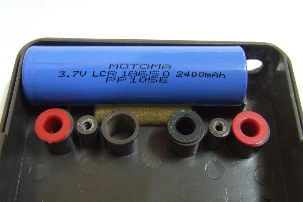
To do this, we will need to solder a 3.7V to 9V upconverter, as well as get a 18650 battery (you can disassemble an unnecessary battery from a laptop or from a Tesla Model S car, there are the same ones).
Step 1. Transfer the multimeter to the battery. Customize the place under 18650.
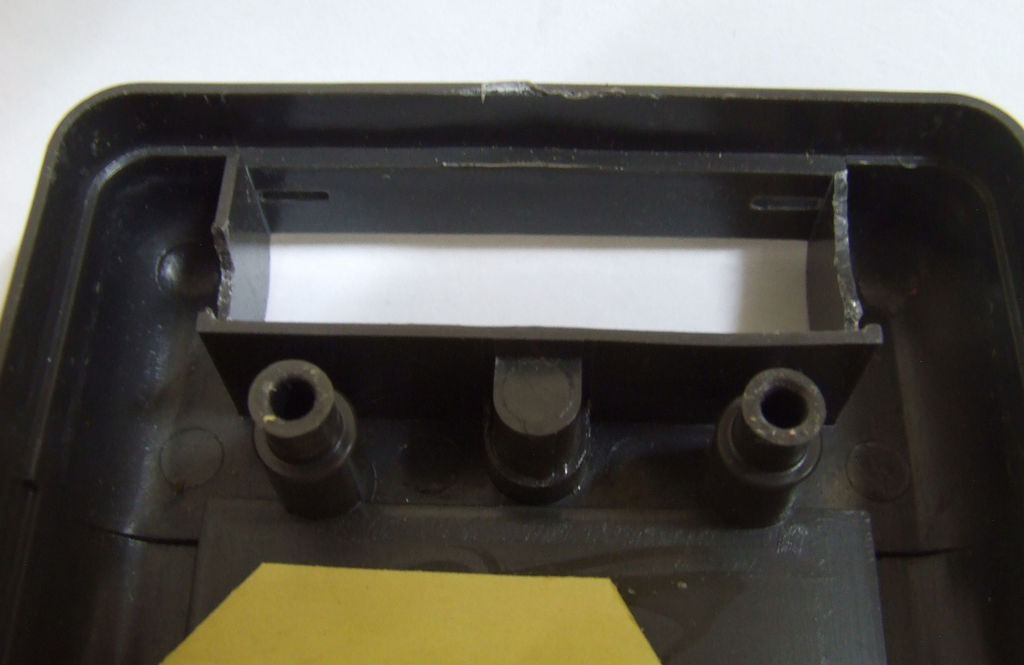

First we need to place all the elements inside the case of the multimeter. To do this, put the battery in place and saw off all interfering plastic housing elements. Do not forget to drill a hole under the battery charging connector.
Step 2. Boost voltage converter.
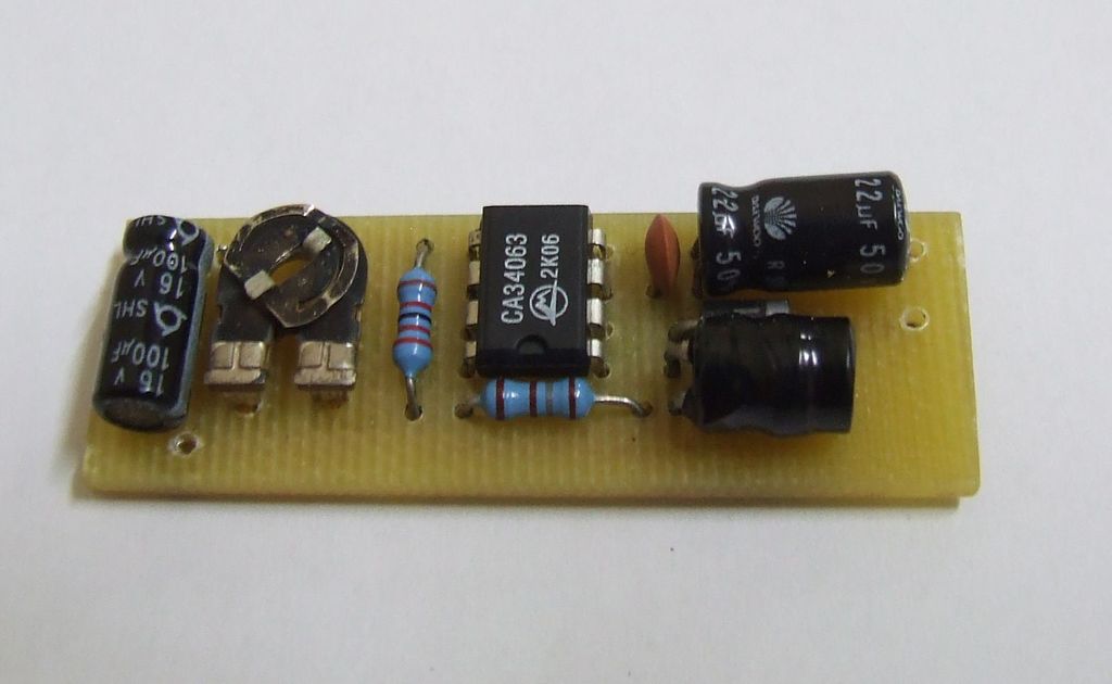
Now we need to solder the boost converter, which will raise the battery voltage from 3.7 to 9 volts. I assembled it on an MC34063A chip. Here is its datashit. Element ratings are not as critical in terms of values as I used a trimming resistor, with which you can precisely set the voltage we need to 9 volts.
Here is a list of components:
- 1 18650 Lithium battery
- 1 dc connector
- 1 22k or 27k resistor
- 1 180 ohm resistor
- 1 10k or 5k variable resistor
- 1 22uF or 47uF electrolytic capacitor
- 1 100uF electrolytic capacitor
- 1 10pF to 50pF ceramic capacitor
- 1 MC34063A
- 1 IN5819 diode
- 1 170uH inductance.
From this link you can download a PCB project in Eagle format.
Step 3. Putting it all together.

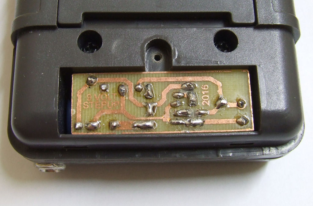
Here it is necessary to get some soldering.
Solder the center pin of the power connector to the positive terminal of the battery.
Solder the side contact of the power connector to the negative terminal of the battery.
From here, we also solder the wire to the negative input of the converter.
Solder the positive contact of the battery to the unused contact on the switch of the multimeter.
Solder the wire from the other side of the multimeter switch to the positive input of the transmitter.
Now solder the wires from the 9 volt power input of the multimeter to the output terminals of the converter.
Adjust the inverter output voltage to 9 volts using a trimming resistor.
Then collect the multimeter back! Transfer of the multimeter to the battery can be considered complete.
Now you never have to buy Krone batteries for your multimeter, you just need to charge its battery.
In contact with