ResistorsThese are radio elements that are widely used to implement various electronic circuits.
Wherein resistors are used to limit the current, to create a voltage drop, as the load from which the useful signal is taken.
Inherently resistors represent active resistance. This means that in an AC circuit, the value of their resistance does not depend on frequency, and the phase of current and voltage coincides.
The main parameters of the resistors are:
- resistance value;
- power dissipation;
- Tolerance from the specified value (accuracy class);
- design features (dimensions, installation method, etc.)
- temperature coefficient of resistance (how the resistance varies with temperature)
The main types of resistors:
— permanent;
— trimmers;
— premen;
— nonlinear (varistors, thermistors, photoresistors).
Resistor power The diagram is usually indicated inside the rectangle:
![]() three slashes 0.05 W
three slashes 0.05 W
![]() two slashes 0.125 W
two slashes 0.125 W
 one slash 0.25 W
![]() one horizontal line 0.5 W
one horizontal line 0.5 W
![]() One vertical bar of 1 W, i.e. Roman numeral one and so on Roman numerals, II, III, IV, V.
One vertical bar of 1 W, i.e. Roman numeral one and so on Roman numerals, II, III, IV, V.
On the parts themselves, resistors, if the size allows, the nominal (resistance value), tolerance, power and type are indicated.
The following notation denominations are most common:
OhmR, E, Ω for example: 47 ohms, 47R, 47 E, 47 Ω is the same. If the nominal is fractional, for example, 4.7 ohms, then instead of a comma there may be one of the signs indicating the unit of measurement 4R7, 4E7, etc.
If the nominal is in kilo-ohms, then instead of ohms they are applied ohmor TO.
If in mega-ohms, moMor M.
In this case, "K" and "M" can also be put instead of a comma.
The tolerance, accuracy class or deviation from the nominal, is a value that indicates by how many percent the actual value of the resistance of the resistor may differ from that indicated on it. The most common are the following notation:
Again, these symbols are applied if the size of the case allows. The value can be applied either in% or the letter indicated by a number in brackets.
Power is denoted by the letters W, W. For example, 2W or 2W.
If the power is not applied, then the power of the resistor can be approximately judged on the basis of its size. The more resistorthe greater the power dissipation. In any case, if there is no labeling, this is precisely determined by the packaging, specification or reference book.
For trimming and variable resistors, such a characteristic is used as the dependence of the change in resistance on the angle of rotation of the resistor handle. This dependence can be of three types: linear, logarithmic or inversely logarithmic. This is important with some adjustments.
The main defects of resistors are breaks. Variables and trimmers plus breakages often break moving contact. Checks the health of resistors with an ohmmeter. Wherein resistor disconnect from the circuit.
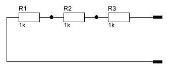
With a series connection, the total resistance is equal to the sum of all resistances. If the ratings are the same, then the powers are the same. If the ratings of the resistances are different, then the power of each is determined individually, as the product of the total current and the voltage drop across this resistor.
In the diagram below, the total resistance:
R total = R 1+ R2 + R3 = 1 + 1 + 1 = 3 kΩ
With a parallel connection, not the resistance of the resistors, but their conductivity. Conductivity is the reciprocal of resistance.
Resistors are electronic devices that resist electrical current.
|
The designation of the resistor on the circuits |
Resistor resistance - its main characteristic. The basic unit of electrical resistance is ohm (ohm). In practice, derivatives are also used — kilohm (kOhm), mega-ohm (MΩ), giga-ohm (GΩ), which are related to the basic unit by the following ratios:  1 kΩ = 1000 ohms,
1 MΩ = 1000 kΩ,
1 GOM = 1000 MΩ.
Resistors can be constant, that is, have constant resistance, and variables, that is, those whose resistance can be changed within certain limits during operation. Resistors are available with specific resistance values in a wide range from ohms to tens of MOhm.
DC resistors
On schematic diagrams, next to the resistor symbol, put down the value of its resistance. Resistance less kilo is recorded as a number without units; resistances from one kilo and higher, but less than one megaoma, are expressed in kilo omes and the letter “k” is placed next to the number; resistances from one megaoma and above are recorded as a number, adding the letter “M” next to it. For example, 10 M (10 meg), 5.1 K (5.1 kilo-ohms); 470 (470 ohms); K68 (680 ohms).
The resistance value is usually indicated on the surface of the resistors. For marking small resistors use an alphanumeric code or a color code consisting of colored stripes.
When using an alphanumeric code, the resistance of the resistors is designated by numbers indicating the unit of measurement. It is customary to denote letters: R - ohm, K - kilo, M - mega.
Resistors nominal deviation
Due to the imperfection of the manufacturing technology of resistors, their resistance may differ from the specified (nominal) value. The industry produces resistors for general use with a tolerance of ± 5%, ± 10%, ± 20%. Therefore, along with the nominal value on the case and in the passport of resistors, the limits of permissible deviations are put down. At the same time, a record of 12k ± 5% means that the nominal value of the resistance of the resistor is 12 kΩ. The actual value may differ from the nominal value, but not more than ± 0.6 kΩ (± 5% from 12 kΩ).
When using color markings, the deviation of the resistor nominal value is indicated by a separate strip (see the table at the bottom of the article).
In measuring electronic devices used resistors high accuracy (the so-called precision resistors).
Resistor power
Thermal energy released in the resistor when current flows is dissipated from its surface into the surrounding space. However, if the power released in the resistor is large, then the heat from its surface will not have time to be removed. The resistor will become excessively hot and may even burn out. Therefore, each resistor has a strictly defined maximum allowable value of the power that it is capable of dissipating.
Power resistors usually they are recognized by their size (the larger the size of the resistor, the greater its power) or by the designation on the housings.
On schematic diagrams, the power of the resistor used is usually indicated. The absence of an indication of the power of the resistor means that negligible power is released on it and any resistor with a given resistance can be used.
Variable resistors
Variable resistor is used for smooth control of current and voltage.
Variable resistors are divided into adjustment and adjusted. Resistors with which they make various adjustments by changing their resistance are called variable resistors or potentiometers. Resistors, the resistance of which change only in the process of establishing (setting) the device, called trimming.
Variable resistors have three outputs, one of which is connected with a moving contact sliding along the surface of the conductive layer. The slider of the adjusting resistor is moved by hand by turning the protruding knob, the trimming knob - with a screwdriver inserted into the slot.
The resistance between any extreme output of the variable resistor and the moving contact depends on the position of the slider.
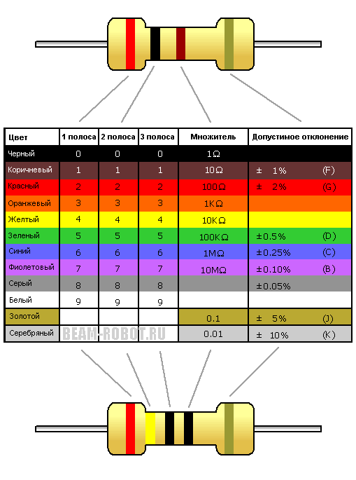
The type of marking in which paint is applied to the body of the resistor in the form of colored rings or dots is called a color code. Each color corresponds to a specific digital value. The color marking on the resistors is shifted to one of the pins and is read from left to right. If, because of the small size of the resistor, the color marking cannot be placed on one of the terminals, then the first sign is made a strip two times wider than the others.
Color marking of foreign small-sized resistors, common in Russia, consists most often of four color rings. The resistance value is determined by the first three rings (two numbers and a multiplier). The fourth ring contains information on the tolerance of resistance from the nominal value in percent.
In order not to confuse zero and the letter "O", "Om" is often written with the letter "omega":
The time for decoding the color code of resistors can be significantly reduced by using a special
A person who is confronted with electrical circuits and devices working from electricity, sometimes deals with a huge number of elements and objects that are actually stuffed with mounting boards. At the moment in electronics is widely used such detail as a resistor. This element can perform a large number of functions at a time. Some schemes do not involve installation without using it. In other words, the resistor is practically nothing to replace.
If we turn to the formation of the word, then by all means the thread will lead to the English word "resist". Translated into Russian, it will denote action - to resist, resist and discourage. It all comes down to the fact that a current flows in the circuit in the circuit, which is opposed to the internal type. The value of this resistance itself can be determined by the properties of various external factors and properties of the conductor.
This type of current characteristic can be measured in ohms. In this case, there will be a direct dependence on the voltage and the strength of the electric current. For example, when the resistance of a wire element is 1 Ohm and a current is 1 Amp, a voltage of 1 Volt will be created at each end of the conductor. From this it follows that with the introduction and change of the resistance value, it will be possible to control and regulate all other parameters. And it is worth noting that they can be calculated independently.
At the moment, resistors are used in many areas of science. In addition, they are considered to be the most common part for the creation of circuit boards and electrical circuits.
The main function of the resistor is to control and limit the action of the current. Everything else, this detail is sometimes used to share the voltage in the network.
If we talk about the principle of work, then it all comes down to a mathematical representation. In this case, any part in the circuit through which the current passes will depend on the voltage formed in it. This dependency can be described using Ohm's law, and the detail is considered as a resistor.
In a standard situation, heat will dissipate on the resistor. Experts say that in electrical circuits it will be necessary to use this element in order to dissipate the necessary power. Among other things, it will be necessary to provide that the increase in the temperature of the resistor does not interfere with the work of the parts located next to it. Based on the mathematical theory, it is possible to calculate the voltage, its resistance and the electrical current index.

It should also be noted that the nominal power of resistors is usually indicated in the component table. But most of them use standard power of 0, 25 or 0.125 watts. If to create a circuit it is necessary to use a higher power resistor, then it is indicated in the preliminary list.
Interesting fact. For the most part, all resistors are composed of silver. But certain options are collected when using gold, platinum, palladium, tantalum and ruthenium.
How to determine the power?
To determine the power index, you must first learn how to decipher the resistor. Especially to facilitate the work of a special label was invented. All of them have a different color designation.
So, on the marking indicate four primary colors:
- first bar - the value of the first digit;
- the second bar is the value of the second digit;
- the third band is a zero number;
- the fourth band is the exact value of the resistor resistance. It is also called admission.

The nominal designation of a resistor by strips can be identified by tabular data and reference materials.
Payment
To perform the calculation of the voltage divider on the resistor, you should use the mathematical formula No. 1.

In fact, the formula is based on Ohm’s law, where:
Uin and Uout - the voltage at the input and output;
R1 R2 is the resistance passing through the resistor.
To calculate the voltage drop across the resistor, use the following mathematical formula:
Where U1 is the voltage drop across the resistor;
I is the strength of the electric current that passes through it;
R is the resistance of the part.
How to calculate the resistance?

Resistors are denoted as R. It should be noted that the resistance of a section of a circuit with three resistors included in it will be the sum of the resistances of these parts.
How to check the resistor?
In order to check the part for performance, it is necessary to simply ring it. To perform this diagnostic procedure, you should use a multimeter. Select the position ohmmeter. The data obtained in the end can be compared with the nominal indicator of resistance, which tentatively indicate on the body of the element, as well as on the circuit diagram.
Compound
At the moment, resistors can crash into the network in several ways:
- the series connection of resistors is the insertion of an element in series from other parts included in the network.
- mixed connection of resistors - in this case, when using several parts, the connection to the network can be made in any way. And it is absolutely not necessary that he will be one. It can be both parallel and serial connection.
Parallel connection
With parallel connection of resistors, their resistance will be the inverse of the nominal value.

As for the power index, it is read on the device case.

Video
Watch the video on what a resistor is and how it works:
In the event that it is impossible to carry out this or that calculation using our own resources, you should seek help from reference materials and other scientific sources.
Oct 9, 2015 Tatyana Sumo
Resistors are the most common elements of electronic equipment. Previously, resistors were called resistances, but in accordance with the State Standard, electrical resistances, as circuit elements, were given the name “resistors”.
This was done in order to distinguish "resistance" as a product (radio component) and "resistance", as its physical property, the electrical quantity. Resistors are characterized by electrical resistance.
The basic unit of electrical resistance in accordance with the international system of units is Ohms. In practice, derivatives are also used - kilohm (kOhm), mega-ohm (MOhm), giga-ohm (GOhm), terahom (Tom), which are related to the basic unit by the following relations:
- 1 kΩ = 10 ^ 3 ohms,
- 1 MΩ = 10 ^ 6 Ohms,
- 1 GΩ = 10 ^ 9 Ohm,
- 1 TΩ = 10 ^ І2 Ohm.
There are the following types of resistors: permanent and variables. Variables are still divided into adjusting and trimming. For fixed resistors, the resistance cannot be changed during operation.
Resistors, with the help of which they make various adjustments in electronic equipment by changing their resistance, are called variable resistors or potentiometers. Those resistors, the resistance of which change only in the process of establishing (setting) the electronic device, called trimmers.
The main parameters of resistors
Resistors are characterized by the following basic parameters: nominal resistance value, tolerance of the resistance from the nominal value, nominal (permissible) dissipation power, maximum operating voltage, temperature coefficient of resistance, intrinsic noise and voltage ratio.
The nominal value of resistance R is usually indicated on the resistor body. The actual value of the resistance of the resistor may differ from the nominal value within the tolerance (tolerance determined in percentage relative to the nominal resistance).
Marking resistors
On the case of a resistor, as a rule, its type, rated power, nominal resistance, tolerance and date of manufacture are applied with paint. For marking small resistors use an alphanumeric code. The code consists of numbers indicating the nominal resistance, a letter indicating the unit of measurement, and a letter indicating the tolerance of the resistance. Examples of the letter code of the units for measuring the nominal resistance of the old and the new standards applied to the resistor case are given in Table. one.
If the nominal resistance is expressed as an integer, then the letter code is put after this number. If the nominal resistance is a decimal fraction, then the letter is placed instead of a comma, separating the whole and fractional parts. In the case when the decimal fraction is less than one, the integer part (zero) is excluded.
When marking resistors, the tolerance code is placed after the coded designation of the nominal resistance. Letter codes of tolerances are given in table. 2
For example, the designation 4К7В (or 4К7М) corresponds to a nominal resistance of 4.7 kΩ with a tolerance of 20%. In tab. Figures 1 and 2 show the letter codes corresponding to both the old and the new standards, since at the present time both variants are encountered. The nominal power on small resistors is not indicated, but is determined by the size of the case.
Table 1. Designation of the nominal value of resistance on the resistor cases.
| Full designation | Abbreviated designation on the body | |||||
| Designation | Designation Examples | Unit designation | Designation Examples | |||
| units of measurement | Old | New | Old | New | ||
| Ohm | Omy | R | E | 13E 470E (K47) | ||
| ohm | kilograms | TO | TO | |||
| MOhm | megaOms | 470 megohm | M | M | M47 | |
Table 2. The letter codes of the tolerances of resistance applied to the housing resistors.
Color code marking resistors
The type of marking in which paint is applied to the body of the resistor in the form of colored rings or dots is called a color code (see Fig. 1). Each color corresponds to a specific digital value.
The color marking on the resistors is shifted to one of the pins and is read from left to right. If the marking cannot be placed on one of the conclusions, then the first sign is made a strip two times wider than the others.
For resistors with a small tolerance (0.1 ... 10%), marking is made with five color rings. The first three rings correspond to the numerical value of resistance in ohms, the fourth ring is the multiplier, and the fifth ring is the tolerance (Fig. 1).
Resistors with a tolerance value of 20% are marked with four colored rings and the tolerance value is not applied to them. The first three rings are the numerical value of the resistance in ohms, and the fourth ring is the multiplier. Sometimes resistors with a tolerance of 20% are marked with three colored rings.
In this case, the first two rings are the numerical value of the resistance in ohms, and the third ring is the multiplier. An insignificant zero in the third digit is not marked.
Due to the fact that foreign products occupy a significant place on the market of radio equipment, we note that resistors of foreign firms are marked with both digital and color code.
When digitally labeled, the first two digits indicate the numerical value of the resistor in ohms, and the rest represent the number of zeros. For example: 150 - 15 Ohm; 181 - 180 ohms; 132 - 1.3 kΩ; 113—11 kΩ.
Color marking usually consists of four color rings. The resistance value represents the first three rings, two digits and a multiplier. The fourth ring contains information on the tolerance of resistance from the nominal value in percent.
Determining the values of foreign resistors on the color code is the same as for domestic ones. Tables of color codes of domestic and foreign resistors are the same.
Many firms, in addition to traditional labeling, use their in-house color and code markings. For example, there is a marking of SMD resistors, when a colon is put instead of the number 8. So, marking 1:23 means 182 kOhm, a 80R6 - 80.6 ohms.
| Color of rings or dots | Nominal resistance, Ohm | Factor | Tolerance,% | TCS,% / HS | ||
| 1st digit | 2nd digit | 3rd digit | 4th digit | 5th digit | p | |
| Silver | - | - | - | 0601 | ± 10 | - |
| Golden | - | - | - | 061 | ± 5 | - |
| The black | - | 0 | - | 1 | - | - |
| Brown | 1 | 1 | 1 | 10 | ± 1 | 100 |
| Red | 2 | 2 | 2 | 10^2 | ± 2 | 50 |
| Orange | 3 | 3 | 3 | 10^3 | - | 15 |
| Yellow | 4 | 4 | 4 | 10^4 | - | 25 |
| Green | 5 | 5 | 5 | 10^5 | ± 0.5 | - |
| Blue | 6 | 6 | 6 | 10^6 | ± 0.25 | 10 |
| Violet | 7 | 7 | 7 | 10^7 | ± 0.1 | 5 |
| Gray | 8 | 8 | 8 | 10^8 | ± 0.05 | - |
| White | 9 | 9 | 9 | 10^9 | - | 1 |
Fig. 1. Color marking of domestic and foreign resistors in the form of rings or points, depending on the tolerance and TKE.
Literature: V.M. Pestrikov. Encyclopedia amateur radio.
All electronic devices contain resistors, which are their main element. With it, change the amount of current in the article presents the properties of resistors and methods for calculating their power.
Assign resistor
Resistors are used to adjust the current in electrical circuits. This property is determined by Ohm’s law:
From the formula (1) it is clearly seen that the smaller the resistance, the stronger the current increases, and vice versa, the smaller the value of R, the greater the current. This property is used in electrical engineering. On the basis of this formula, current divider circuits are widely used in electrotechnical devices.
In this circuit, the current from the source is divided into two, inversely proportional to the resistance of the resistors.
In addition to adjusting the current, resistors are used in this case. Ohm’s law is again used, but in a slightly different form:
From the formula (2) it follows that with increasing resistance increases voltage. This property is used to build voltage divider circuits.
It is clear from the circuit and formula (2) that the voltages across the resistors are distributed in proportion to the resistances.
The image of resistors on the circuits
According to the standard, resistors are depicted as a rectangle with dimensions of 10 x 4 mm and are denoted by the letter R. Often the power of resistors is indicated in the diagram. The image of this indicator is performed by oblique or straight lines. If the power is more than 2 watts, then the designation is made in Roman numerals. This is usually done for wire resistors. In some states, such as the United States, other conventions apply. To facilitate the repair and analysis of the circuit, the power is often provided, which is performed according to GOST 2.728-74.
Technical specifications of devices
The main characteristic of the resistor is the nominal resistance R n, which is indicated on the circuit near the resistor and on its case. The unit of measure for resistance is om, kilo, and mega. Resistors with resistance from fractions of an ohm to hundreds of megohms are made. There are many technologies for the production of resistors, they all have advantages and disadvantages. In principle, there is no technology that would allow absolutely accurate manufacture of a resistor with a given resistance value.
The second important characteristic is the resistance deviation. It is measured in% of the nominal R. There is a standard deviation resistance range: ± 20, ± 10, ± 5, ± 2, ± 1% and further down to the value of ± 0.001%.
The next important characteristic is the power resistors. During operation, they heat up from the current passing through them. If the power dissipation exceeds the allowable value, the device will fail.
When heating, the resistors change their resistance, therefore, for devices operating in a wide temperature range, one more characteristic is introduced - the temperature coefficient of resistance. It is measured in ppm / ° C, that is, 10 -6 R n / ° C (one millionth part of R n at 1 ° C).
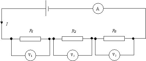
Series connection resistors
Resistors can be connected in three different ways: serial, parallel, and mixed. When the current alternately passes through all resistances.

With such a connection, the current at any point in the circuit is the same, it can be determined by Ohm's law. The impedance of the circuit in this case is equal to the sum of the resistances:
R = 200 + 100 + 51 + 39 = 390 ohms;
I = U / R = 100/390 = 0.256 A.
Now you can determine the power in series connection of resistors, it is calculated by the formula:
P = I 2 ∙ R = 0.256 2 ∙ 390 = 25.55 W.
The power of the remaining resistors is determined similarly:
P 1 = I 2 ∙ R 1 = 0.256 2 ∙ 200 = 13.11 W;
P 2 = I 2 ∙ R 2 = 0.256 2 ∙ 100 = 6.55 W;
P 3 = I 2 ∙ R 3 = 0.256 2 ∙ 51 = 3.34 W;
P 4 = I 2 ∙ R 4 = 0.256 2 ∙ 39 = 2.55 W.
If you add up the power of resistors, you get a complete P:
P = 13.11 + 6.55 + 3.34 + 2.55 = 25.55 watts.
Parallel connection of resistors
With parallel connection, all the beginning of the resistors are connected to one node of the circuit, and the ends - to another. With such a connection, the current forks and flows through each device. The magnitude of the current, according to Ohm’s law, is inversely proportional to the resistance, and the voltage across all resistors is the same.
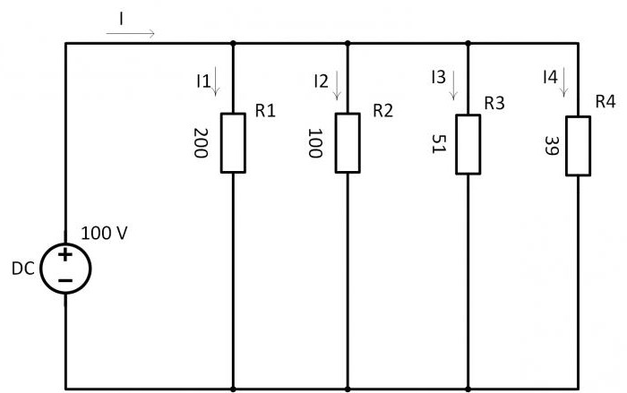
1 / R = 1 / R 1 + 1 / R 2 + 1 / R 3 + 1 / R 4 = 1/200 + 1/100 + 1/51 + 1/39 = 0.005 + 0.01 + 0,0196 + 0.0256 = 0.06024 1 / ohm.
Resistance is the inverse of conductivity:
R = 1 / 0.06024 = 16.6 ohms.
Using the Ohm's law, they find the current through the source:
I = U / R = 100 ∙ 0.06024 = 6.024 A.
Knowing the current through the source, find the power of parallel-connected resistors by the formula:
P = I 2 ∙ R = 6.024 2 ∙ 16.6 = 602.3 W.
According to Ohm’s law, the current through resistors is calculated:
I 1 = U / R 1 = 100/200 = 0.5 A;
I 2 = U / R 2 = 100/100 = 1 A;
I 3 = U / R 1 = 100/51 = 1.96 A;
I 1 = U / R 1 = 100/39 = 2.56 A.
P 1 = U 2 / R 1 = 100 2/200 = 50 W;
P 2 = U 2 / R 2 = 100 2/100 = 100 W;
P 3 = U 2 / R 3 = 100 2/51 = 195.9 W;
P 4 = U 2 / R 4 = 100 2/39 = 256.4 W.
If all this is added up, then the power of all the resistors is obtained:
P = P 1 + P 2 + P 3 + P 4 = 50 + 100 + 195.9 + 256.4 = 602.3 W.
Mixed compound
Mixed resistor circuits contain a series and simultaneously parallel connection. This circuit is easy to convert by replacing the parallel connection of resistors with a serial one. To do this, first replace the resistances R 2 and R 6 with their total R 2,6, using the formula below:
R 2,6 = R 2 ∙ R 6 / R 2 + R 6.
In the same way, two parallel resistors R 4, R 5 are replaced by one R 4,5:
R 4,5 = R 4 ∙ R 5 / R 4 + R 5.
The result is a new, simpler scheme. Both schemes are shown below.

The power of the resistors on the circuit with a mixed connection is determined by the formula:
To calculate by this formula, first find the voltage at each resistance and the amount of current through it. You can use another method to determine the power of the resistors. To do this, use the formula:
P = U ∙ I = (I ∙ R) I = I 2 ∙ R.
If only the voltage across the resistors is known, then another formula is used:
P = U ∙ I = U (U / R) = U 2 / R.
All three formulas are often used in practice.
Calculation of circuit parameters
The calculation of the circuit parameters consists in finding the unknown currents and voltages of all the branches in the sections of the electrical circuit. With this data, you can calculate the power of each resistor included in the circuit. Simple methods of calculation were shown above, in practice the situation is more complicated.
In real circuits, the connection of resistors by a star and a triangle is often found, which creates considerable difficulties in calculations. To simplify such schemes, methods for transforming a star into a triangle and vice versa have been developed. This method is illustrated in the diagram below:
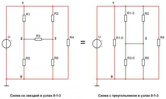
The first scheme incorporates a star connected to nodes 0-1-3. Resistor R1 is connected to node 1, R3 is connected to node 3, and R5 is connected to node 0. In the second circuit, triangle resistors are connected to nodes 1-3-0. The node 1 is connected to the resistors R1-0 and R1-3, to the node 3 - R1-3 and R3-0, and to the node 0 - R3-0 and R1-0. These two schemes are completely equivalent.
To go from the first circuit to the second, the resistances of the triangle resistors are calculated:
R1-0 = R1 + R5 + R1 ∙ R5 / R3;
R1-3 = R1 + R3 + R1 ∙ R3 / R5;
R3-0 = R3 + R5 + R3 ∙ R5 / R1.
Further transformations are reduced to the calculation of parallel and series-connected resistances. When the impedance of the circuit is found, find the current through the source according to Ohm’s law. Using this law, it is easy to find the currents in all branches.
How to determine the power of resistors after finding all the currents? To do this, use the well-known formula: P = I 2 ∙ R, applying it for each resistance, we find their power.
Experimental determination of the characteristics of circuit elements
To experimentally determine the necessary characteristics of elements, it is required to assemble a given circuit from real components. After that, with the help of electrical measuring instruments perform all the necessary measurements. This method is time consuming and expensive. Developers of electrical and electronic devices use simulators for this purpose. With the help of them all the necessary calculations are made, and the behavior of the circuit elements in different situations is modeled. Only after that the prototype of the technical device is assembled. One of such popular programs is the powerful Multisim 14.0 modeling system from National Instruments.
How to determine the power of resistors using this program? This can be done in two ways. The first method is to measure current and voltage with an ammeter and a voltmeter. Multiply the measurement results, get the desired power.

From this scheme, we determine the power of resistance R3:
P 3 = U ∙ I = 1.032 0.02 = 0.02064 W = 20.6 mW.
The second method is the direct measurement of power using a wattmeter.
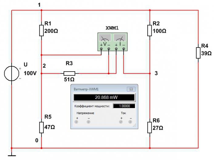
From this scheme it is seen that the power of resistance R3 is equal to P 3 = 20.8 mW. The discrepancy due to the error in the first method is greater. The power of the other elements is determined in the same way.